

Page 1
FALL PROTECTION
PROTECCIÓN CONTRA CAÍDAS
USER INSTRUCTIONS
INSTRUCCIONES PARA EL USUARIO
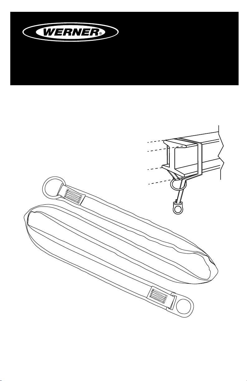
SOFT ANCHORAGE CONNECTOR
Complies with ANSI Z359.1-2007,
OSHA 1910 and 1926 requirements.
CONECTOR DE ANCLAJE FLEXIBLE
Cumple con las normas ANSI Z359.1-2007,
OSHA 1910 y 1926.
(See back page for specic model numbers.)
(Vea la página trasera para obtener los números de modelo especícos).
Werner Fall Protection 724-588-2000
93 Werner Rd. 888-523-3371 toll free/ llamada gratuita
Greenville, PA 16125 888-456-8458 fax
Page 2
CAUTION!
If use of fall protection equipment is necessary then the work
environment is dangerous and potentially deadly. Werner Company
products are designed to eliminate as much of the hazard as possible
but can do that ONLY if they are used correctly. Use this equipment as
it was designed to be used, after appropriate training, under the direct
supervision of a competent person, according to the instructions
provided, and in accordance with OSHA and local safety regulations.
User MUST read and understand all cautions and instructions. Failure
to heed these guidelines could result in injury or even death. Please,
WORK SAFE! WORK SMART!
ENGLISH
Page 2
Page 3

SOFT ANCHORAGE CONNECTOR
USER INSTRUCTIONS
Contents
I. BEFORE USING THE ANCHORAGE CONNECTOR ........................................ 4
a. Inspect ......................................................................................................................4
b. Compatibility ............................................................................................................6
c. Clearance ..................................................................................................................6
d. Rescue Plan .............................................................................................................6
e. Training .....................................................................................................................6
II. ANCHORAGE CONNECTOR INSTALLATION AND USE ................................ 6
a. Cable and Webbing Slings, Chokers and Cross-arm Straps ................................6
b. Anchorage Structure ...............................................................................................7
c. Cable Chokers ..........................................................................................................8
d. Cross-arm Straps / Webbing Chokers ....................................................................9
e. Cable Anchor Extensions ......................................................................................10
f. Pour-In Anchor Straps ...........................................................................................11
III. USE WARNINGS, RESTRICTIONS AND CAUTIONS ................................... 12
a. Fall Distance ..........................................................................................................12
b. Swing Fall Hazard ..................................................................................................13
c. Rated Capacity .......................................................................................................13
d. Environmental Hazards .........................................................................................13
e. Components/Subsystems .....................................................................................14
IV. LABELS/IDENTIFICATION/INSPECTION RECORDS .................................. 14
V. EQUIPMENT RECORDS ................................................................................18
VI. INSPECTION RECORDS .............................................................................. 18
ENGLISH
Page 3
Page 4
Warning:
This product is just one part of a personal fall arrest system. It must
be matched correctly with other components to form a complete and
functional system. The user must understand the function of each of
these components and follow the manufacturer’s instructions for use
for each. The user must be provided these instructions, should read
and follow them, and consult the competent person who will supervise
his work if he has any questions about any part of the instructions.
The employer must provide training in the proper use, inspection, and
maintenance of all components in the system, and these instructions
can be used as part of that training. The equipment should be used
ONLY in accordance with these instructions, local ordinances and
codes, the applicable OSHA and ANSI standards, and the employer’s
safety plan.
These devices are designed to provide an anchorage connection
between fall protection products and/or anchorages, for both fall
protection and fall restraint. They can accommodate attachment
options for a variety of fall protection products for fall protection or
rescue equipment that might be required, so long as the rated capacity
is not exceeded.
IF YOU HAVE ANY QUESTIONS ABOUT ANYTHING IN THESE
INSTRUCTIONS, THE EQUIPMENT, OR PROPER USE OF THE
EQUIPMENT, CONTACT WERNER CO. FOR MORE INFORMATION.
I. Before Using the Anchorage Connector
Before using this equipment the user should take certain steps to
ensure that it is in suitable condition and safe for use. Users must
read and understand these instructions. It is the employer’s obligation
to ensure that all users have been trained in safe work procedures as
well as in the use and limitations of fall protection equipment. All users
should be aware of and comply with all applicable OSHA, ANSI, CSA
and local or regional regulations concerning fall protection equipment
and its use.
a. Inspect
Examine all equipment thoroughly, daily before use by the user,
ENGLISH
Page 4
and periodically by a competent person who is not the user.
Page 5
SOFT ANCHORAGE CONNECTOR
USER INSTRUCTIONS
1. Verify the condition of each component. If any damage or
abnormalities are found the equipment should be removed from
service.
2. Check the webbing for cuts, abrasion, burns, welding spatter, or
discoloration that could be caused by chemical exposure.
3. For cable legs examine the entire length for any breaks, and the
swaged ttings for any irregularities.
4. Check all stitching for any broken threads.
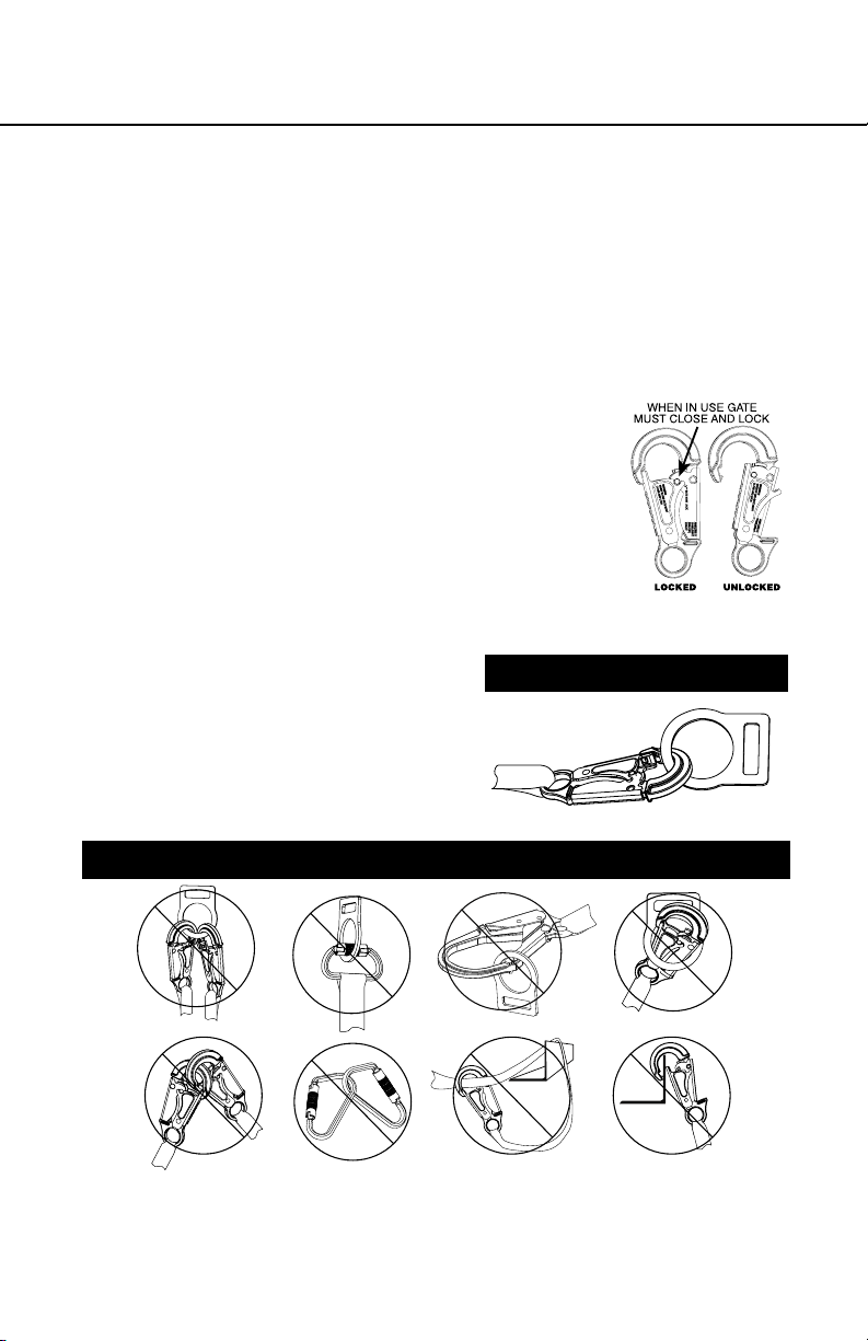
5. Check all hardware for cracks, bends,
irregularities, corrosion, or sharp edges.
Check the snap hook gates for proper
smooth operation. The engagement
release for the hook’s gate is visible for
inspectability. Ensure the mechanism is
undamaged and functioning correctly.
6. Verify that all labels are intact, in place, and legible.
If abnormalities are found in
any of these areas, then the
competent person should be
consulted to determine if that
item is safe for continued use
or if it should be removed from
service.
PROPER CONNECTIONS
INAPPROPRIATE CONNECTIONS
A. B.
NO! NO! NO! NO!
D. E. F.
C.
NO!NO!NO!NO!
ENGLISH
Page 5
Page 6
b. Compatibility
Verify compatibility of any subsystems being used. Werner
products connected to Werner products should be compatible, but
connection to other products should be veried by a competent
person for compatibility to ensure there is no accidental detachment
from side-loading, rollout, non-standard closures, etc.
c. Clearance.
Verify that adequate clearance exists below the work area and
there are no objects or obstructions below the work area that the
user could contact in the case of a fall.
d. Rescue Plan
If a worker falls and is forced to remain suspended for any length
of time, physical damage to the body or even death can result. For
this reason Werner, OSHA, ANSI, CSA and most local regulations
require that a rescue plan and the means to implement the rescue
plan are in place before use of this equipment.
e. Training
OSHA, ANSI, and most local ordinances require that workers using
this product receive adequate training before use of this product.
These instructions and their entire contents should be a part of that
training.
II. Anchorage Connector Installation and Use
a. Cable and Webbing Slings, Chokers and Cross-arm Straps
Also known as tie-off adapters, these devices are designed to
wrap around a structure which is the anchorage. They act as
a connector to that anchorage for attachment of a complete fall
protection system. All have D-rings, O-rings, or web loops and are
passed around the structure and then secured by being passed
back through the second O-ring, D-ring or web loop to “choke” the
anchorage.
Warning:
Webbing chokers and cross arm straps should not be left installed
permanently outdoors since prolonged exposure to the environment
and especially to UV in sunlight will degrade the webbing, reducing
ENGLISH
tensile strength.
Page 6
Page 7

SOFT ANCHORAGE CONNECTOR
USER INSTRUCTIONS
b. Anchorage Structure
Inspect the anchorage structure to ensure it is of adequate strength
and is sound, without sharp edges, corrosion, cracks or anything
else that could weaken the connection. The connectors can be
used vertically, but ensure that the choker has some stop so it will
not be able to move on the structure in the case of a fall.
1. For fall arrest, anchors need to have strength of either 5000
lbs per attached user (22.2kN), or be certied by a qualied
person to have strength of not less than 3600 lbs per attached
user (16kN).
2. For fall restraint (where there is no possibility of accidental
detachment), anchors need to withstand a static load of 3000
lbs per attached user (13.3 kN), or be certied by a qualied
person to be able to withstand two times the foreseeable force.
3. For positioning systems, the anchorage strength must be a
minimum of 3000 lbs per attached user (13.3 kN), or be certied
by a qualied person to have strength of twice the foreseeable
force.
4. For rescue systems, the anchorage should withstand a static
load of 3000 lbs per attached user (13.3kN) or be certied by a
qualied person for ve times the foreseeable load.
Page 7
ENGLISH
Page 8
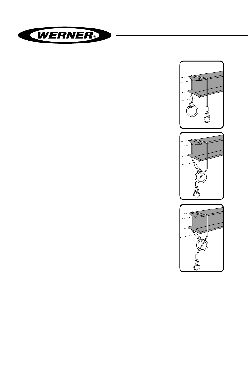
c. Cable Chokers
Cable chokers are used when the anchorage
they are being connected to will not be
damaged by the cable in the case of a fall,
such as structural I-beams, or when the
choker will be left in place and subjected to the
environment for an extended period of time.
Installing Cable Chokers
1. Pass cable over structure with choker ends
dangling on either side. Pass the small
O-ring on one end through the larger O-ring
on the other end. Pull small O-ring to tighten
(choke) the structure.
2. Continue to pass the extended cable end
around the beam or other anchor until
there is not enough length left to make
another complete revolution. Then “choke”
the anchor by passing the smaller O-ring
through the larger. The small O-ring will
become the anchorage point for a complete
fall protection system.
While it is preferable to make several
turns of the cabling around the anchorage
before “choking” it, in cases where a lower
anchorage connection is needed the
connector can be choked with only one turn
around the beam before passing the small
O-ring through the larger O-ring. This is
also a convenient way to adjust the length
of the choker slightly.
3. Connect fall protection system to the small O-ring.
ENGLISH
Page 8
Page 9
SOFT ANCHORAGE CONNECTOR
USER INSTRUCTIONS
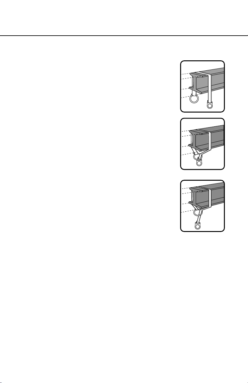
d. Cross-arm Straps / Webbing Chokers
Web chokers work the same as cable chokers,
but the wider surface of the webbing means that
the impact in the case of a fall will be spread over
a larger area considerably reducing the impact
per square inch.
Installing Cross-arm Straps
1. With labels on outward facing surface of strap.
Pass web over structure with choker ends
dangling on either side. Pass the small D-ring
or O-ring on one end through the larger
D-ring, O-ring or web loop on the other end.
Pull small D-ring or O-ring to tighten (choke)
the structure.
2. Continue to pass the extended web end
around the beam or other anchor until there
is not enough length left to make another
complete revolution, then “choke” the anchor
by passing the smaller O-ring or D-ring
through the larger O-ring or web loop. The
small D-ring will become the anchorage point
for a complete fall protection system.
It’s preferable but not necessary to make
several turns of the webbing around the anchorage before
“choking” by passing the small D-ring or O-ring through the
larger O-ring or web loop. This is also a convenient way to adjust
the length of the cross arm strap slightly.
Warning:
3. Connect fall protection system to the smaller D-ring or O-ring.
ENGLISH
Page 9
Page 10

ENGLISH
Page 10
e. Cable Anchor Extensions
Cable anchor extensions come in various
standard lengths. They differ from cable
chokers because they are intended
to extend the position of an existing
anchorage connector to within reach of a
user, so the extensions have a snap-hook on one end to connect
to the existing anchorage connector, and an O-ring on the other, to
provide the new extended anchorage connection for the user.
Installing a Cable Anchor Extension
1. Calculate the needed extension length considering the worker’s
needs and the available fall distance to be sure there will not be
any contact with any object in the fall path. Connect the snap
hook to the existing fall protection anchorage. Connect ONLY
with the snap hook and NEVER loop the extender around the
anchorage as you would a choker.
2. The user should connect to the extender’s O-ring as he would to
any other suitable anchorage.
CAUTION:
Anchor extensions are not cable
chokers and should not be used
as such. The ONLY approved
fall protection attachment
point is to the O-ring. NEVER
connect two snap hooks to
one O-ring or the snap hook
to the cable. Connect it ONLY
to the existing anchorage.
The Anchorage Extenders are
not anchorages themselves.
They are only extensions of
an existing anchorage. ONLY
connect the Anchor Extensions
to an overhead anchor and
never in any position that could
increase the user’s fall distance
beyond the allowable free fall
distance of 6 feet.
Page 11
SOFT ANCHORAGE CONNECTOR
USER INSTRUCTIONS
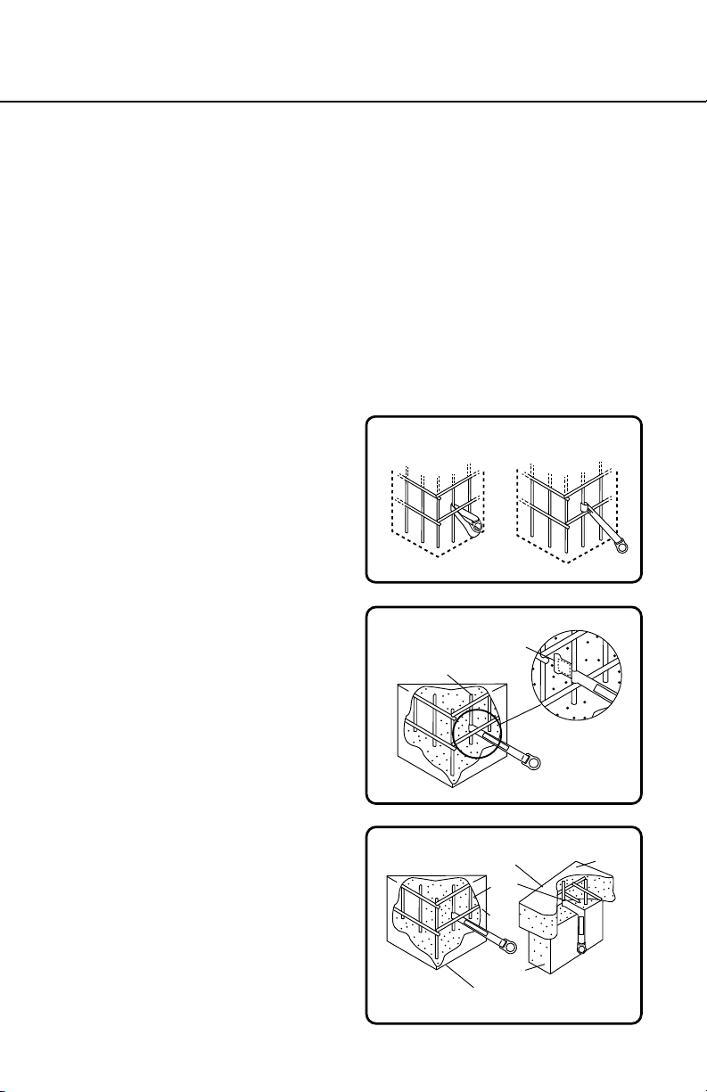
f. Pour-In Anchor Straps
Pour-in-place anchors are actually simplied standard web chokers
that have been modied to continue functioning as an anchorage
connector after being partially embedded in concrete. As such they
conform to most of the same instructions and warnings contained
in the previous Cross arm strap/ webbing choker section. All Werner
Pour-In anchors are for one-time use only.
Installing a Pour-In Anchor Strap
1. Select a location with required anchorage strength and
unobstructed fall clearance. Either place the strap’s loop end
over the rebar or use the
loop to “choke” it. To choke
it, loop strap around
the re-bar and pull the
exposed end (with loop
or D-ring) through the end
loop. Tighten the choke
on the rebar. Position the
exposed end with the
other loop or D-ring at
least six inches outside
the form. Secure the strap
so that it can not be pulled
inside when the concrete
is poured. Position the
strap’s wear protector so
it will be partly embedded
in the poured concrete
and partly exposed. It’s
important that the wear
protector is positioned
to protect the main loadbearing webbing from
contact with the sharp
edge of the poured
concrete.
Installing on Completed Cage
Anchorage Connector Installed
Steel
Re-bar
Concrete
Column
Anchorage Connector Installed
4” min
Steel
Re-bar
Shear
Wall
Web Cut
Line
Poured
Concrete
Floor
Concrete
Column
Imbedded Concrete
Anchor Strap
ENGLISH
Page 11
Page 12

2. The user should connect to the Pour-In Anchor’s D-ring or loop
as he would to any other suitable anchorage.
When connecting to a web loop use ONLY a carabiner, NEVER
a snaphook. Never connect two users to the same anchorage.
Never connect two snap hooks or carabiners to the same
connector.
3. Cut off and discard exposed portion of anchor strap after use.
III. Use Warnings, Restrictions and Cautions
a. Fall Distance
Equipment is designed for a maximum free fall of 6 feet. Contact
with a lower level can occur even when this equipment is in perfect
operating condition if there is any object in the path of the fall or
if the height of the anchorage being used is inadequate. The fall
distance can vary according to the connecting subsystem used. The
following diagrams indicate typical clearance calculations for shock
absorbing lanyards and self-retracting lifelines. While these are
typical situations, the authorized/competent person on site should
make these determinations for each work situation depending on
the site-specic conditions.
Fall distance for shock absorbing lanyards
Energy
Free Fall
Absorbing
Lanyard
Working Level
Length of Anchorage Connector
6 ft.
Length of Lanyard
4 ft.
Deceleration Free Fall Distance
1 ft. Harness Stretch
(Free Fall +
Deceleration)
Total Fall
Distance
11 ft.
Total Estimated
Fall Distance
18 ft.
ENGLISH
Page 12
Lower Level or Obstruction
5 ft.
To Worker’s Back D-Ring
2 ft.
Safety Factor
Page 13

SOFT ANCHORAGE CONNECTOR
USER INSTRUCTIONS
Fall distance for self-retracting lifeline
Self Retracting
Lifeline
Working Level
Lower Level or Obstruction
Swing Fall Hazard
Bottom of Retractable Lifeline
2 ft.
Maximum Free Fall
2.5 ft.
Maximum Deceleration
1 ft. Harness Stretch
5 ft.
To Worker’s Back D-Ring
2 ft.
Safety Factor
Maximum Arrest
Distance (per ANSI)
4.5 ft.
Anchorages
Total Estimated
Fall Distance
12.5 ft.
Position the worker below the
anchorage so if a fall occurs the
worker will not swing into an object
below the work surface.
c. Rated Capacity.
Correct Incorrect
1. Capacity: 310 lbs., including tools and equipment (one person)
2. Strength: For fall arrest OSHA requires a static tensile strength of
5000 lbs. This connector satises the OSHA and ANSI strength
requirements when used in accordance with OSHA, ANSI, CSA
standards, local regulations and the manufacturer’s instructions.
3. These anchors are for fall protection, fall restraint and rescue
use only. They are not designed to hang, support, or lift materials
or equipment.
b .
SWING FALL
HAZARD
d. Environmental Hazards.
This equipment is to be used only under the direct supervision of
a competent person who is able to identify hazards that must be
avoided. These include electricity, chemicals, machinery or moving
objects, sharp edges, damaged anchorages or structures, or any
other element that could damage this equipment or prevent it from
operating as intended.
Page 13
ENGLISH
Page 14

e. Components/Subsystems
Before rst use a qualied person should inspect and determine that
all components and subsystems are compatible and will perform
correctly when combined into a complete personal fall protection
system. Consult the information in these instructions, and if any
additional information is needed contact Werner Co. directly.
IV. Labels/Identication/Inspection Records
a. All products should be inspected by the user thoroughly before
each use. Additional inspections by a competent person other than
the user should be conducted at intervals of no less than one year.
That interval should be shortened any time the product is used in a
harsh environment or is exposed to conditions such as chemicals,
abrasion, heat or any other factor that could affect the strength of
any of the materials or components.
b. The product labels provide an inspection grid to record these
inspections by a competent person. Use a punch or permanent
marker to record those dates.
c. This manual should always accompany the product, or be on le
with the employer for access when needed. Record the identication
details for the anchor and record the inspections in the inspection
log, on page 18. It is important to keep this log current, complete,
and available as needed.
ENGLISH
Page 14
Page 15

SOFT ANCHORAGE CONNECTOR
USER INSTRUCTIONS
front back
Id label
ENGLISH
Page 15
Page 16

ENGLISH
Page 16
front back
Warning label Chokes & Extensions
Page 17

SOFT ANCHORAGE CONNECTOR
USER INSTRUCTIONS
front back
Warning Label Pour-In anchors
ENGLISH
Page 17
Page 18

V. Equipment Record
PART NUMBER
SERIAL NUMBER
DATE
MANUFACTURED
PURCHASE DATE
ASSIGNED TO
SPECIFICATIONS
Werner SOFT ANCHORAGE
Certied to meet ANSI Z359.1-2007, and OSHA 1910 and 1926
standards and regulations for the lanyard component of a
complete personal fall arrest system. All hardware certied to
5000 lb. breaking strength, 100 percent proof tested to 3600 lbs.
Individually bar coded model and serial numbers, location and date of
manufacture are on product label.
VI. Inspection Record
INSPECTION RECORD
DAT E INSPECTOR PASS/FAILDAT E INSPECTOR PASS/FAIL
ENGLISH
Page 18
Page 19

CONECTOR DE ANCLAJE FLEXIBLE
INSTRUCCIONES PARA EL USUARIO
¡PRECAUCIÓN!
Si el uso de equipos de protección contra caídas es necesario, entonces el
ambiente de trabajo es peligroso y potencialmente mortal. Los productos
Werner Company están diseñados para eliminar peligros tanto como sea
posible, pero SÓLO si estos productos se utilizan correctamente. Utilice este
equipo ya que éste fue diseñado para usarse, utilice este equipo después
de una capacitación apropiada, bajo la supervisión directa de una persona
calicada, de acuerdo con las instrucciones suministradas, y de acuerdo con
las regulaciones OSHA y las regulaciones de seguridad locales. El usuario
DEBE leer y entender todas las precauciones e instrucciones. No tener en
cuenta estas directrices podría resultar en lesiones o incluso la muerte. Por
favor, ¡TRABAJE DE MANERA SEGURA! ¡TRABAJE DE MANERA INTELIGENTE!
Página 2
ESPAÑOL
Page 20

Contenido
I. ANTES DE UTILIZAR EL CONECTOR DE ANCLAJE ..................................... 4
a. Inspeccione .............................................................................................................4
b. Compatibilidad ........................................................................................................6
c. Espacio libre ...........................................................................................................6
d. Plan de rescate .......................................................................................................6
e. Capacitación ...........................................................................................................6
II. INSTALACIÓN Y USO DEL CONECTOR DE ANCLAJE .................................6
a. Eslingas de correa tejida y de cable, correas de estrangulación y
correas de cruzar ....................................................................................................6
b. Estructura del anclaje.............................................................................................7
c. Cables de estrangulación ......................................................................................8
d. Correas tejidas de estrangulación / correas de cruzar .......................................9
e. Extensiones de anclajes de cable .......................................................................10
f. Correas de anclaje instalables durante el vertido de concreto
III. TENGA EN CUENTA LAS ADVERTENCIAS, RESTRICCIONES
Y PRECAUCIONES ................................................................................... 12
a. Distancia de caída..................................................................................................12
b. Peligro de caída tipo columpio ............................................................................13
c. Capacidad nominal ................................................................................................13
d. Peligros ambientales .............................................................................................13
e. Componentes/Subsistemas ..................................................................................14
IV. ETIQUETAS/IDENTIFICACIÓN/REGISTROS DE INSPECCIÓN .................. 14
V. REGISTROS DE EQUIPOS ............................................................................ 18
........................11
VI. REGISTROS DE INSPECCIÓN ..................................................................... 18
ESPAÑOL
Página 3
Page 21

CONECTOR DE ANCLAJE FLEXIBLE
INSTRUCCIONES PARA EL USUARIO
Advertencia:
Este producto es sólo una parte del sistema personal de detención de
caídas. Éste debe combinarse correctamente con otros componentes para
conformar un sistema completo y funcional. El usuario debe entender la
función de cada uno de estos componentes y seguir las instrucciones del
fabricante para el uso de cada componente. El usuario debe recibir estas
instrucciones, debe leerlas y seguirlas, y consultar a la persona calicada que
supervisará su trabajo si tiene alguna pregunta acerca de cualquier parte de
las instrucciones. El empleador debe proporcionar capacitación sobre el uso
apropiado, inspección y mantenimiento de todos los componentes del sistema,
y estas instrucciones pueden utilizarse como parte de esa capacitación. El
equipo SÓLO debe utilizarse de acuerdo con estas instrucciones, ordenanzas
y códigos locales, las normas OSHA y ANSI aplicables, y el plan de seguridad
del empleador.
Estos dispositivos están diseñados para proporcionar una conexión de
anclaje entre los productos de protección contra caídas y/o los anclajes, para
protección contra caídas y evitamiento de caídas. Éstos pueden incorporar
opciones de sujeción para una variedad de productos de protección contra
caídas para equipos de protección contra caídas o de rescate que pudieran
requerirse, siempre y cuando no se exceda la capacidad nominal.
SI USTED TIENE ALGUNA PREGUNTA ACERCA DE ALGO DE ESTAS
INSTRUCCIONES, EL EQUIPO O EL USO APROPIADO DEL EQUIPO,
COMUNÍQUESE CON WERNER CO. PARA OBTENER MÁS INFORMACIÓN.
I. Antes de utilizar el conector de anclaje
Antes de utilizar este equipo, el usuario debe realizar ciertos pasos para
garantizar que éste está en condiciones apropiadas y es seguro para su uso.
Los usuarios deben leer y entender estas instrucciones. Es obligación del
empleador garantizar que todos los usuarios hayan recibido capacitación
sobre los procedimientos de trabajo seguros y también sobre el uso y
limitaciones de los equipos de protección contra caídas. Todos los usuarios
deben estar informados acerca de y cumplir todas las normas OSHA, ANSI,
CSA y las normas locales o regionales relacionadas con los equipos de
protección contra caídas y su uso.
a. Inspeccione
Todo el equipo debe ser examinado completamente, diariamente antes
del uso, por parte del usuario; y periódicamente por parte de una persona
calicada que no sea el usuario.
Página 4
ESPAÑOL
Page 22

1. Verique la condición de cada componente. Si se encuentra cualquier
daño o anormalidad, el equipo debe retirarse del servicio.
2. Revise las correas tejidas en busca de cortaduras, abrasión,
quemaduras, salpicadura de soldadura, o decoloración que pudiera
haberse causado por exposición a productos químicos.
3. Para los tramos de cuerda/cable, examine toda la longitud en busca de
cualquier rotura y examine los acoples forjados en busca de cualquier
irregularidad.
4. Revise todas las costuras en busca de hilos
rotos.
CUANDO ESTÁ EN USO,
EL CIERRE DEBE QUEDAR
CERRADO Y ASEGURADO
5. Revise todos los herrajes en busca de grietas,
dobladuras, irregularidades, corrosión o bordes
losos. Revise los ganchos de cierre resortado
para vericar el funcionamiento sin problemas.
El liberador de enganche del cierre del gancho
es visible para inspeccionabilidad. Verique
ASEGURADO
DESASEGURADO
que el mecanismo no tiene daños y está funcionando correctamente.
6. Verique que todas las etiquetas están intactas, en su sitio, y son legibles.
Si se encuentran anormalidades
en alguna de estas áreas,
CONEXIONES APROPIADAS
entonces debe consultarse a la
persona capacitada para que
determine si ese elemento es
seguro para continuar su uso o si
debe retirarse del servicio.
CONEXIONES INAPROPIADAS
A. B.
NO! NO! NO! NO!
D. E. F.
ESPAÑOL
Página 5
C.
NO!NO!NO!NO!
Page 23

CONECTOR DE ANCLAJE FLEXIBLE
INSTRUCCIONES PARA EL USUARIO
b. Compatibilidad
Verique la compatibilidad de todos los subsistemas que se están
utilizando. Los productos Werner conectados con productos Werner son
compatibles, pero la conexión con otros productos debe ser vericada,
por una persona capacitada, en cuanto a compatibilidad para garantizar
que no haya desconexión accidental por carga lateral, rodaje, cierres noestándares, etc.
c. Espacio libre.
Verique que existe una altura libre adecuada debajo del área de trabajo y
que no hay objetos ni obstrucciones debajo del área trabajo que el usuario
pudiera contactar en caso de una caída.
d. Plan de rescate
Si un trabajador cae y queda obligado a permanecer suspendido durante
cualquier período de tiempo, podría producirse daño físico o incluso la
muerte. Por este motivo, Werner, las regulaciones de OSHA, ANSI, CSA,
y la mayoría de las regulaciones locales exigen la existencia de un plan
de rescate y los medios para ejecutar un plan de rescate, antes del uso
de este equipo.
e. Capacitación
Las regulaciones OSHA, ANSI, y la mayoría de las regulaciones locales
exigen que los trabajadores que utilizan este producto reciban capacitación
adecuada antes del uso de este producto. Estas instrucciones y su
contenido completo deben ser parte de esa capacitación.
II. Instalación y uso del conector de anclaje
a. Eslingas de correa tejida y de cable, correas de estrangulación y
correas de cruzar
También conocidas como adaptadores de amarre, estos dispositivos
están diseñados para envolverse alrededor de una estructura que es el
anclaje. Éstas actúan como conector para ese anclaje para la sujeción de
un sistema completo de protección contra caídas. Todas tienen anillos en
“D”, anillos en “O”, o lazos tejidos, y se pasan alrededor de una estructura
y luego se aseguran pasándose de regreso a través del segundo anillo en
“O”, anillo en “D” o lazo tejido para “estrangular” el anclaje.
Advertencia:
Las correas tejidas de estrangulación y las correas de cruzar no deben
dejarse instaladas de manera permanente en exteriores ya que la exposición
prolongada al ambiente y especialmente a la luz ultravioleta de la luz solar
degradarán la correa tejida, reduciendo la resistencia a la tracción.
Página 6
ESPAÑOL
Page 24

b. Estructura del anclaje
Inspeccione la estructura del anclaje para garantizar que tiene la
resistencia adecuada y es sólido, sin bordes losos, corrosión, grietas ni
nada que pudiera debilitar la conexión. Los conectores pueden utilizarse
verticalmente, pero verique que el estrangulador tiene algún tope de
modo que éste no podrá moverse sobre la estructura en caso de una
caída.
1. Para la detención de caídas, los anclajes deben tener una resistencia
de 5000 lbs por cada usuario conectado (22.2kN), o ser certicados
por una persona calicada indicando que tienen una resistencia no
inferior a 3600 lbs. por cada usuario conectado (16kN).
2. Para el evitamiento de caídas (donde no hay posibilidad de desconexión
accidental), los anclajes deben soportar una carga estática de 3000
lbs por cada usuario conectado (13.3kN), o ser certicados por una
persona calicada para poder soportar dos veces la fuerza previsible.
3. Para los sistemas de puesta en posición, la resistencia mínima de los
anclajes debe ser de 3000 lbs por cada usuario conectado (13.3 kN), o
ser certicados por una persona calicada para una resistencia de dos
veces la fuerza previsible.
4. Para los sistemas de rescate, los anclajes deben soportar una carga
estática de 3000 lbs por cada usuario conectado (13.3kN) o ser
certicados por una persona calicada para cinco veces la carga
previsible.
ESPAÑOL
Página 7
Page 25

CONECTOR DE ANCLAJE FLEXIBLE
INSTRUCCIONES PARA EL USUARIO
c. Cables de estrangulación
Los cables de estrangulación se utilizan cuando
el anclaje al cual se está conectando no será
dañado por el cable en caso de una caída, tal como
vigas en “I” estructurales, o cuando el cable de
estrangulación se dejará en sitio y se expondrá al
ambiente durante un período de tiempo prolongado.
Instalación de cables de estrangulación
1. Pase el cable sobre la estructura con los
extremos del cable de estrangulación colgando
sobre cualquier lado. Pase el anillo en “O”
pequeño de un extremo a través del anillo en
“O” más grande del otro extremo. Hale el anillo
en “O” pequeño para apretar (estrangular) la
estructura.
2. Continúe pasando el extremo del cable extendido
alrededor de la viga u otro anclaje hasta que
no quede suciente longitud para realizar otra
revolución completa. Luego “estrangule” el
anclaje pasando el anillo en “O” más pequeño
a través del anillo en “O” más grande. El anillo
en “O” pequeño se convertirá en el punto de
anclaje para un sistema completo de protección
contra caídas.
Aunque es preferible realizar varios giros
del cable alrededor del anclaje antes de
“estrangularlo”, en casos donde se necesita
una conexión de anclaje más baja, el conector
puede estrangularse con sólo una vuelta
alrededor de la viga antes de pasar el anillo en
“O” pequeño a través del anillo en “O” más grande. Ésta también es
una manera conveniente de ajustar levemente la longitud del cable de
estrangulación.
3. Conecte el sistema de protección contra caídas al anillo en “O” pequeño.
Página 8
ESPAÑOL
Page 26

d. Correas tejidas de estrangulación / correas de
cruzar
Las correas tejidas de estrangulación funcionan igual
a los cables de estrangulación, pero la supercie
más ancha del tejido signica que el impacto en
caso de una caída será distribuido sobre una área
mayor reduciendo considerablemente el impacto por
pulgada cuadrada.
Instalación de las correas
1. Con las etiquetas en la supercie dirigida hacia
afuera de la correa. Pase la correa tejida sobre
la estructura con los extremos de la correa tejida
de estrangulación colgando sobre cualquier lado.
Pase el anillo en “D” o anillo en “O” pequeño de
un extremo a través del anillo en “D”, anillo en “O”
o lazo tejido más grande del otro extremo. Hale el
anillo en “D” o anillo en “O” pequeño para apretar
(estrangular) la estructura.
2. Continúe pasando el extremo tejido extendido
alrededor de la viga u otro anclaje hasta que
no quede suciente longitud para realizar otra
revolución completa, luego “estrangule” el anclaje
pasando el anillo en “O” o anillo en “D” más
pequeño a través del anillo en “O” o lazo tejido
más grande. El anillo en “D” pequeño se convertirá
en el punto de anclaje para un sistema completo de protección contra
caídas.
ESPAÑOL
Página 9
Es preferible pero no necesario realizar varios giros de la correa tejida
alrededor del anclaje antes de “estrangular” pasando el anillo en “D”
o anillo en “O” pequeño a través del anillo en “O” o lazo tejido más
grande. Ésta también es una manera conveniente de ajustar levemente
la longitud de la correa.
3. Conecte el sistema de protección contra caídas al anillo en “D” o anillo
en “O” más pequeño.ing:
Page 27

CONECTOR DE ANCLAJE FLEXIBLE
INSTRUCCIONES PARA EL USUARIO
e. Extensiones de anclaje de cable
Las extensiones de anclaje de cable vienen
en diferentes longitudes estándares. Éstas
son diferentes de los cables de estrangulación
porque éstas están diseñadas para extender
la posición de un conector de anclaje existente
hasta dentro del alcance de un usuario, así que
las extensiones tienen un gancho de cierre resortado en un extremo para
conectar con el conector de anclaje existente, y un anillo en “O” en el otro
extremo, para proporcionar la nueva conexión de anclaje extendida para el
usuario.
Instalación de una extensión de anclaje de cable
1. Calcule la longitud de extensión necesaria considerando las necesidades del
trabajador y la distancia de caída disponible para garantizar que no habrá
ningún contacto con ningún objeto en la trayectoria de caída. Conecte el
gancho de cierre resortado al anclaje de protección contra caídas existente.
SÓLO conecte con el gancho de cierre resortado y NUNCA envuelva el
extensor alrededor del anclaje como usted lo haría con un estrangulador.
2. El usuario debe conectarse al anillo en “O” del extensor tal como lo haría con
cualquier otro anclaje apropiado.
PRECAUCIÓN:
Las extensiones de anclaje no
son cables de estrangulación y
no deben utilizarse como tales.
El ÚNICO punto de sujeción
de protección contra caídas
aprobado es con el anillo en “O”.
Nunca conecte dos ganchos de
cierre resortado con un (1) anillo
en “O” ni el gancho de cierre
resortado con el cable. Conéctelo
ÚNICAMENTE al anclaje existente.
Los extendedores de anclaje
no son anclajes por sí mismos.
Estos sólo son extensiones de un
anclaje existente. SÓLO conecte
las Extensiones de Anclaje a un
anclaje elevado y nunca en una
posición que pudiera aumentar
la distancia de caída del usuario
más allá de la distancia de caída
libre permisible de 1.8 m (6 pies).
Anillo en “O”
Cuerda salvavidas horizontal
en anclaje elevado
Gancho de cierre
resortado
Extensión de anclaje
Anillo en “O”
Argolla metálica
Cuerda salvavidas auto-
retráctil
Anillo en “D” Dorsal
Anclaje elevado
Gancho de cierre
resortado
Extensión de anclaje
Anillo en “O”
Anillo en “D” Dorsal
ESPAÑOL
Página 10
Page 28

f. Correas de anclaje instalables durante el
vertido de concreto
Los anclajes instalables durante el vertido
de concreto son realmente correas tejidas
de estrangulación estándares simplicadas
que han sido modicadas para continuar
funcionando como conector de anclaje
después de ser empotradas parcialmente
dentro de concreto. Como tal, éstas siguen
la mayoría de las mismas instrucciones
y advertencias contenidas en la anterior
sección “Correa tejida de estrangulación
/ correa de cruzar”. Todos los anclajes
instalables durante el vertido de concreto
de Werner sólo son para un (1) uso.
Instalación de una correa de anclaje
instalable durante el vertido de
concreto
1. S eleccione un lugar que tenga la
resistencia de anclaje requerida
y un espacio libre de caída sin
obstrucciones. Coloque el extremo
de lazo de la correa sobre la barra
de refuerzo o utilice el lazo para
“estrangularla”. Para estrangular la
barra de refuerzo, envuelva la correa
alrededor de la barra de refuerzo y
hale el extremo expuesto (con lazo
o anillo en “D”) a través del lazo de
extremo. Apriete el estrangulador
sobre la barra de refuerzo. Coloque
el extremo expuesto con el otro lazo
o anillo en “D” a al menos 6 pulgadas
afuera del molde/encofrado. Asegure
la correa de modo que ésta no pueda
halarse adentro cuando se vierta el
concreto. Coloque el protector de
desgaste de la correa de modo que
este protector quedará parcialmente
empotrado en el concreto vertido y
parcialmente expuesto. Es importante
colocar el protector de desgaste para
proteger el tejido de soporte de carga
ESPAÑOL
principal contra el contacto con el
borde loso del concreto vertido.
Installing on Completed Cage
Instalación en jaula completa
Anchorage Connector Installed
Conector de anclaje, instalado
Barra de refuerzo
Steel
de acero
Re-bar
Columna de
Concrete
Column
Conector de anclaje, instalado
Anchorage Connector Installed
Re-bar
Pared en
de concreto
Correa de anclaje
Imbedded Concrete
empotrada en concreto
Anchor Strap
Línea de
Web Cut
corte del
tejido
concreto
4” min
Barra de
Steel
refuerzo
de acero
Shear
corte
Wall
Concrete
Columna
Column
Line
Piso de
Poured
concreto
Concrete
vertido
Floor
Página 11
Page 29

CONECTOR DE ANCLAJE FLEXIBLE
INSTRUCCIONES PARA EL USUARIO
2. El usuario debe conectarse al anillo en “D” o lazo del anclaje instalable
durante el vertido de concreto tal como lo haría con cualquier otro anclaje
apropiado. Al conectarse con un lazo tejido, SÓLO utilice una argolla
metálica (carabiner), NUNCA un gancho de cierre resortado. Nunca
conecte dos usuarios al mismo anclaje. Nunca conecte dos ganchos de
cierre resortado al mismo conector.
3. Corte y deseche la porción expuesta de la correa de anclaje después del
uso.
III. Tenga en cuenta las advertencias, restricciones y precauciones
a. Distancia de caída
El equipo está diseñado para una caída libre máxima de 1.8 m (6 pies). Aún
cuando este equipo esté en perfectas condiciones de funcionamiento podría
ocurrir contacto con un nivel inferior si hay algún objeto en la trayectoria de
la caída o si es inadecuada la altura del anclaje que se está utilizando. La
distancia de caída puede variar de acuerdo con el subsistema conectivo
utilizado. Los siguientes diagramas indican los cálculos de espacio libre
típico para cuerdas absorbedoras de impacto y cuerdas salvavidas autoretráctiles. Aunque éstas son situaciones típicas, la persona autorizada/
calicada en sitio debe realizar estas decisiones para cada situación de
trabajo dependiendo de las condiciones especícas del sitio.
Distancia de caída para las cuerdas absorbedoras de impacto
Cuerda
Energy
absorbedora
Caída libre
Free Fall
Absorbing
de energía
Lanyard
Nivel de trabajo
Working Level
Nivel inferior u obstrucción
Lower Level or Obstruction
Longitud del conector del anclaje
Length of Anchorage Connector
6 ft.
1.8 m (6 pies)
Length of Lanyard
Longitud de la cuerda
1.2 m (4 pies)
4 ft.
Distancia de caída libre con
Deceleration Free Fall Distance
desaceleración
1 ft. Harness Stretch
0.31 m (1 pie) de alargamiento del arnés
1.5 m (5 pies)
5 ft.
To Worker’s Back D-Ring
al anillo en “D” de espalda del trabajador
0.6 m (2 pies)
2 ft.
Safety Factor
Factor de seguridad
Distancia
Total Fall
total de caída
Distance
(caída libre +
(Free Fall +
desaceleración)
Deceleration)
3.4 m
11 ft.
(11 pies)
Distancia de caída
Total Estimated
estimada total
Fall Distance
5.5 m (18 pies)
18 ft.
Página 12
ESPAÑOL
Page 30

ESPAÑOL
Distancia de caída para cuerda salvavidas auto-retráctil
Cuerda
Self Retracting
salvavidas
Lifeline
auto-retráctil
Working Level
Nivel de trabajo
Nivel inferior u obstrucción
Lower Level or Obstruction
b. Peligro de caída tipo columpio
Posicione el trabajador debajo del
anclaje de modo que si ocurre una
caída, el trabajador no se columpiará
hacia un objeto debajo de la supercie
de trabajo.
c. Capacidad nominal.
1. Capacidad: 310 lbs., incluyendo las
herramientas y equipos (1 persona)
2. Resistencia: Para la detención de caídas, OSHA exige una resistencia
estática a la tracción de 5000 lbs. Este conector satisface los requisitos
de resistencia de OSHA y ANSI cuando se utiliza de acuerdo con las
normas OSHA, ANSI, CSA, las regulaciones locales y las instrucciones
del fabricante.
3. Estos anclajes sólo son para protección contra caídas, evitamiento
de caídas y uso para rescate. Estos no están diseñados para colgar,
soportar o levantar materiales o equipos.
d. Peligros ambientales.
Este equipo sólo debe utilizarse bajo la supervisión directa de una persona
competente que pueda identicar los peligros que deben evitarse. Éstos
incluyen la electricidad, productos químicos, máquinas u objetos en
movimiento, bordes losos, estructuras o anclajes dañados, o cualquier
otro elemento que pudiera dañar este equipo o que evite que funcione
según se pretende.
Parte inferior de la unidad de cuerda salvavidas retráctil
Bottom of Retractable Lifeline
0.6 m (2 pies)
2 ft.
Caída libre máxima
Maximum Free Fall
0.8 m (2.5 pies)
2.5 ft.
Desaceleración máxima
Maximum Deceleration
1 ft. Harness Stretch
0.31 m (1 pie) de alargamiento del arnés
5 ft.
1.5 m (5 pies)
To Worker’s Back D-Ring
al anillo en “D” de espalda del trabajador
0.6 m (2 pies)
2 ft.
Factor de seguridad
Safety Factor
Distancia máxima
Maximum Arrest
para detención
Distance (per ANSI)
(según ANSI)
4.5 ft.
1.4 m (4.5 pies)
Anclajes
Anchorages
Correct Incorrect
Correcto
Distancia de caída
Total Estimated
estimada total
Fall Distance
3.8 m (12.5 pies)
12.5 ft.
Incorrecto
PELIGRO DE
SWING FALL
CAÍDA TIPO
HAZARD
COLUMPIO
Página 13
Page 31

CONECTOR DE ANCLAJE FLEXIBLE
INSTRUCCIONES PARA EL USUARIO
e. Componentes/Subsistemas
Antes del primer uso, una persona calicada debe inspeccionar y decidir que
todos los componentes y subsistemas son compatibles y que funcionarán
correctamente en combinación con un sistema personal completo de
protección contra caídas. Consulte la información en estas instrucciones, y
si se requiere cualquier información adicional, comuníquese directamente
con Werner Co.
IV. Etiquetas/Identicación/Registros de inspección
a. Todos los productos deben ser inspeccionados completamente por el
usuario antes de cada uso. Una persona calicada, diferente al usuario,
debe realizar inspecciones adicionales en intervalos no inferiores a un (1)
año. Ese intervalo debe acortarse cada vez que el producto se utiliza en
un ambiente agresivo o se expone a condiciones tales como productos
químicos, abrasión, calor o cualquier otro factor que pudiera afectar la
resistencia de cualquiera de los materiales o componentes.
b. Las etiquetas del producto proporcionan una tabla de inspección para que
una persona calicada registre estas inspecciones. Utilice un punzón o
marcador permanente para registrar estos datos.
c. Este manual siempre debe acompañar el producto o estar en los archivos
del empleador para consultarlo cuando se requiera. Registre los detalles
de identicación para el anclaje y registre las inspecciones en el registro
de inspección mostrado en la página 18. Es importante mantener este
registro actualizado, completo y disponible según se requiera.
Página 14
ESPAÑOL
Page 32

ESPAÑOL
Página 15
parte delantera
Etiqueta de identicación
parte trasera
Page 33

CONECTOR DE ANCLAJE FLEXIBLE
INSTRUCCIONES PARA EL USUARIO
parte delantera parte trasera
Etiqueta de advertencia para los
estranguladores y extensiones
ESPAÑOL
Página 16
Page 34

ESPAÑOL
Página 17
front back
Etiqueta de advertencia para los anclajes
instalables durante el vertido de concreto
Page 35

V. Registro del equipo
NÚMERO DE
PIEZA
NÚMERO DE SERIE
FECHA DE
FABRICACIÓN
FECHA DE COMPRA
ASIGNADO A
ESPECIFICACIONES
ANCLAJE FLEXIBLE de Werner
Certicado para cumplir las regulaciones y normas ANSI Z359.1-2007
y OSHA 1910 y 1926 para los componentes de cuerdas de sistemas
personales completos de detención de caídas. Como mínimo, todos
los herrajes están certicados para una resistencia a la rotura de 5000
lb., 100% probados para 3600 lbs.
Los números de modelo y números de serie, sitio y fecha de fabricación,
con código de barras individual, están en la etiqueta del producto.
VI. Registro de inspección
REGISTRO DE INSPECCIÓN
FECHA INSPECTOR APROBADO/
NO-APROBADO
FECHA INSPECTOR APROBADO/
NO-APROBADO
Page 36

Werner Soft Anchorage Model Numbers Included
Se incluyen los números de modelo de anclajes
exibles de Werner
A111002
A111003
A111004
A111006
A111008
A 11110 2
A 11110 3
A 11110 4
A 11110 6
A 11110 8
A112002
A112003
A112004
A112006
A112008
A113002
A113003
A113004
A113006
A113008
A211002
A211003
A211004
A211103
A211104
A211106
A211006
Werner Co. Fall Protection
93 Werner Rd. Greenville, PA 16125
724-588-2000 • 888-523-3371 toll free/ llamada gratuita • 888-456-8458 fax
PN103774-01 ©2012 Werner Co. Rev C 2/14
 Loading...