

Werma Signaltechnik 646 700 55, 646 700 54, 840 700 55, 840 700 54 Instructions for use [ml]
SIGNALTECHNIK
Bedienungsanleitung
GSM-Funkelement
IP65: 646 700 55 (24V); 646 700 54 (12V)
IP54: 840 700 55 (24V); 840 700 54 (12V)
Funktion
Das GSM-Funkelement in Verbindung mit WERMA Signalsäulen benachrichtigt Sie bei auftretenden Produktionsstörungen jederzeit und überall auf Ihrem Handy
Sicherheitshinweise
Achtung!
• Beachten Sie auch die Anleitung der
Signalsäule.
• Setzen Sie das GSM-Funkelement
nicht für sicherheitsrelevante Anwendungen ein.
• Die Ansteuerung der Signalsäule mit
pulsierendem Signal (Blinklicht) führt
nicht zu einer Benachrichtigung auf
Ihrem Handy.
• Verwendung nur mit 24 V oder
12 V Säulen.
Technische Daten
Maße (Ø x Höhe) 70 mm x 65 mm
Gehäuse Polycarbonat
Betriebstemperatur -20 °C bis +50 °C
Stromaufnahme 50 mA 80 mA
Max. Stromaufnahme 450 mA
(kurzzeitig)
Betriebsspannung 24 V= 12 V=
Das GSM-Funkelement darf nur mit
geregelter Gleichspannung
(24 V= ± 15%; 12 V=+15%/-10%)
betrieben werden.
GSM-Frequenz 900 bzw. 1800 MHz, (alle gängigen
Netze der EU)
Steckplatz SIM-Karte SIM-Karte nicht im Lieferumfang
enthalten!
Antennenanschluss FME-Steckverbindung
(im Lieferumfang enthalten)
Konformität Die Normen ETSI EN 301 489-1 V1.4.1
(08-2002), ETSI EN 301 489-7 V1.2.1
(08-2002) und EN 61000-4-5:1995
werden eingehalten.
EN 60947-5-1 wird erfüllt.
650 mA
(kurzzeitig)
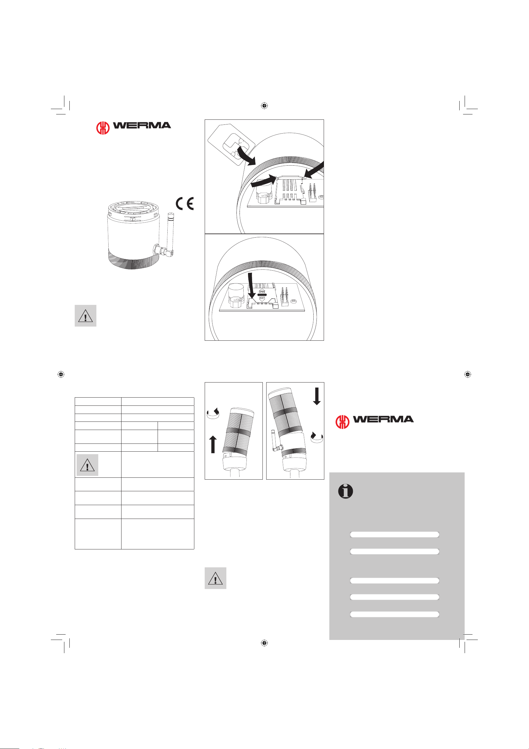
Einsetzen der SIM-Karte
1. Legen Sie die SIM-Karte für das GSM-Funkelement in ein
Handy ein. Beachten Sie die Bedienungsanleitung des
Handys.
2. Setzen Sie die PIN-Nummer der SIM-Karte auf 0000.
3. Deaktivieren Sie die Mailbox-Funktion und die Rufnummer-Unterdrückung der SIM-Karte für das GSM-Funkelement!
4. Legen Sie die SIM-Karte in das GSM-Funkelement ein wie
unten beschrieben.
5. Deaktivieren Sie die Rufnummer-Unterdrückung des
Mastertelefons.
Montage
1. Stecken Sie die Antenne auf. Drehen Sie die Gewindehülse handfest an!
2. Setzen Sie das GSM-Funkelement als unterstes Element
auf. Beachten Sie die Markierungen am Gehäuse.
Versorgungsspannung
Das GSM-Funkelement entnimmt seine Versorgungsspannung aus einem beliebigen Leuchtelement der Signalsäule.
Es gibt zwei Wege, die Inbetriebnahme durchzuführen:
1. Betriebsleuchte vorhanden, Spannung liegt im Betriebszustand an. Spannungsversorgung ist gewährleistet.
2. Keine Betriebsleuchte vorhanden, nur Störleuchten:
Spannungsversorgung nur im Störungsfall.
Führen Sie bei Inbetriebnahme einen Lampentest durch
oder führen Sie bewusst eine Störmeldung herbei. Über
eine beliebige Signal-Leuchte wird das GSM-Funkelement
mit Spannung versorgt.
Achtung!
• Bestimmte Funktionen (z. B. Statusabfrage) des GSM-Funkelements
stehen nur zur Verfügung, wenn eine
konstante Spannungsversorgung
gewährleistet ist.
• Verwenden Sie in Verbindung mit
dem GSM-Funkelement möglichst
eine Betriebsmeldeleuchte!
Ein- Ausschalten des
GSM-Funkelements
Die Alarmfunktionen lassen sich deaktivieren, ohne die
Konfi gurationen zu verändern:
1. durch Anrufen des GSM-Funkelements (gebührenfrei),
2. durch Senden von SMS mit entsprechenden Befehlen,
3. durch Ansteuerung eines Inputs im Modus „Externe
Ansteuerung“.
Alarmmeldungen werden bei Deaktivierung nicht gespeichert, sie werden verworfen. Nach Reaktivierung werden nur
aktuelle Alarmzustände gemeldet.
1. Ein- und Ausschalten über Anruf
Ausschalten (gebührenfrei)
Rufen Sie das GSM-Funkelement vom Mastertelefon aus an!
Der Anruf wird nach 15 Sekunden abgewiesen. Eine Bestätigung gibt es nicht.
Einschalten (gebührenfrei)
Rufen Sie das GSM-Funkelement vom Mastertelefon aus an!
Beenden Sie den Anruf nach dem zweiten Klingelton. Eine
Bestätigung gibt es nicht.
2. Ein- und Ausschalten per SMS
Der Befehl „STOFF“ deaktiviert, der Befehl „STON“ aktiviert.
Mit einem ohne Leerzeichen angehängten „+“ erhalten Sie
eine Bestätigungs-SMS.
Beispiel: STOFF+
3. Ein- und Ausschalten über externe Ansteuerung
Das GSM-Funkelement wird über einen externen Schalter
bzw. über die Steuerung ein- oder ausgeschaltet. Zur Aktivierung dieser Funktion müssen die Parameter c9 und ggf. c10
der Standardkonfi guration verändert werden (siehe Tabelle).
Beispiel:
Auswahl des Betriebsmodus über Stufe 2:
conf, gsm1c9:1c10:0100
Wird die entsprechende Stufe mit Spannung versorgt, ist
das GSM-Funkelement ausgeschaltet (keine Spannung =
eingeschaltet).
Es können dann noch die Signale von 3 Stufen der Signalsäule über das GSM-Funkelement weitergeleitet werden.
Einsatz von Pre-Paid-SIM-Karten
Pre-Paid-SIM-Karten haben eine begrenzte Lebensdauer
und ein begrenztes Guthaben. Ist die Gültigkeit überschritten
oder das Guthaben verbraucht, ist die Funktion des GSMFunkelements nicht gewährleistet!
- Laden Sie die Pre-Paid-Karte rechtzeitig auf! Beachten Sie
dazu die Hinweise des Providers.
- Sie müssen ihre Pre-Paid-Karte zum Aufl aden in ein Handy
einlegen.
SIGNALTECHNIK
WERMA SIGNALTECHNIK GMBH + CO. KG
D-78604 Rietheim-Weilheim
Fon +49 (0) 74 24 95 57-222
Fax +49 (0) 74 24 95 57-44
www.werma.de
info@werma.de
310.840.011.0605
Hinweis
•
Bitte tragen Sie die wichtigen Nummern zum
Nachschlagen hier ein.
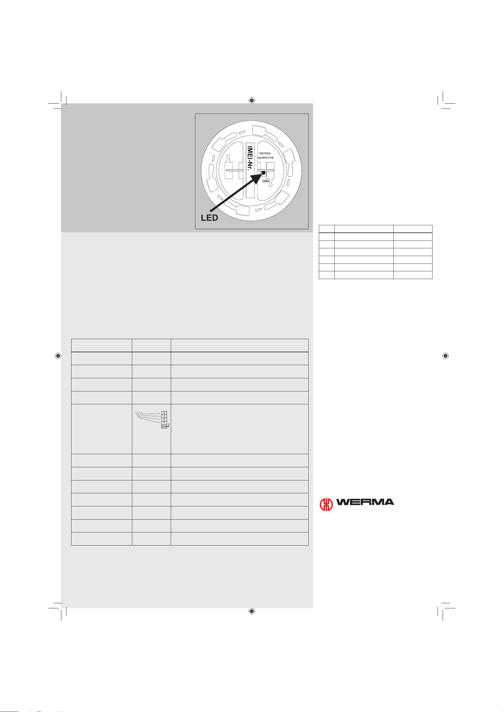
IMEI Geräte-ID-Nr. (siehe: Etikett auf der Oberseite des GSM-Funkelements / Illustration bei
„EASY“ Konfi guration / „Abfrage des Status“ )
SIM-Karten-Rufnummer GSM-Funkelement
Rufnummer Mastertelefon
Dieses Gerät muss SMS absetzen können, sonst
ist keine Parametrierung möglich.
Rufnummer Operator 2
Rufnummer Operator 3
310_840_011_0605_d.indd 1310_840_011_0605_d.indd 1 06.06.2005 11:26:0206.06.2005 11:26:02
„EASY“ Konfi guration
GSM-Funkelement aktivieren:
- Mindestens ein Element der Signalsäule muss leuchten.
Beachte: Sobald das Modul Spannung hat, ist es 10 Minuten empfangsbereit. Danach schaltet es sich wieder ab.
- Die Zustands-LED auf der Oberseite muss dabei von ca.
5 s Dauerlicht auf 1 x Blinken (200 ms Intervall) mit 1 s
Pause wechseln.
- Wählen Sie die Nummer des GSM-Funkelements mit Ihrem
Mastertelefon. Warten Sie, bis das Quittierungszeichen
ertönt. Danach beenden Sie den Anruf.
- Sie erhalten eine Konfi gurations-SMS als Bestätigung
- Das GSM-Funkelement ist betriebsbereit. Solange ein Signal mindestens 30 s (mit Betriebsleuchte) bzw. 60 s (ohne)
an der Säule anliegt, wird eine SMS an das Mastertelefon
versendet.
Für eine individuelle Anpassung lesen Sie das Kapitel
„EXPERT“ Konfi guration.
„EXPERT“ Konfi guration
Mit der „EXPERT“ Konfi guration haben Sie die Möglichkeit das GSM-Funkelement über SMS individuell zu konfi gurieren.
Vorgehensweise
- Schicken Sie eine SMS (Struktur und Inhalt siehe Beispiele) an die Rufnummer des GSM-Funkelements.
- SMS kann nur vom Mastertelefon versendet werden.
- Beachten Sie, dass am GSM-Funkelement Spannung anliegt.
Schreibweise der Konfi gurations-SMS
- Jede Konfi gurations-SMS muss mit „conf,gsm1“ beginnen.
- Immer ohne Semikolon schreiben.
- Leerzeichen, Punkt und Komma sind erlaubt.
- Groß- und Kleinschreibung wird ignoriert.
- Die Parameter sind mit einem Leerzeichen getrennt ().
- Die Alarmtexte müssen mit einem Semikolon abgeschlossen werden! Alarmtexte können maximal 120 Zeichen Ascii-Text
haben (siehe Beispiele).
- Wollen Sie eine Bestätigung vom GSM-Funkelement, fügen Sie mit Leerzeichen ein „+“ als letztes Zeichen an die SMS.
- Eine Bestätigungs-SMS erhält ausschließlich das Mastertelefon.
konfi gurierbare
Parameter
c1:
Geräte ID (Name)
c2:
Rufnummer Mastertelefon
c3:
Rufnummer Operator 2
c4:
Rufnummer Operator 3
c5:
Input Maske Master
c6:
Input Maske Operator 2
(optional)
c7:
Input Maske Operator 3
(optional)
c8:
Dauer des Alarm-Anrufs
c9:
Betriebsmodus
c10:
Maske für ext. Ansteuerung
c11:
Alarmtext 1
c12:
Alarmtext 2
c13:
Alarmtext 3
c14:
Alarmtext 4
1111: 1. Ziffer = 1. Stufe, 2. Ziffer = 2. Stufe, 3. Ziffer = 3. Stufe, 4. Ziffer = 4. Stufe.
Voice Call ist ein gebührenfreier Anruf.
Beispiele:
1. Ändern der Geräte ID auf „Maschine1“ mit Bestätigungs-SMS:
conf,gsm1c1:Maschine1+ „+“ = Bestätigung
2. Zusätzliche Meldung an den zweiten Anschluss (z. B. Festnetzanschluss), Voice Call und SMS, bei Signal an erster Stufe der
Signalsäule mit Bestätigungs-SMS:
conf,gsm1c3:+4974249557222c6:3000+
Grundeinstellung
letzte 6 Stellen der
IMEI-Nr
- max. 20-stellige Rufnummer im internationalen Format (mit „+“)
- max. 20-stellige Rufnummer im internationalen Format (mit „+“),
- max. 20-stellige Rufnummer im internationalen Format (mit „+“),
1111 4-stellige Information, welche Inputs Benachrichtigungen in welcher
0000
0000
10 in Sekunden, Wertebereich 2 bis 60
0 Information über verschiedene Betriebszustände
0001 Eine der 4 Stufen wird als „Alarm deaktiviert“-Input genutzt.
Signal 1 Ascii-Text, max. 120 Zeichen
Signal 2 Ascii-Text, max. 120 Zeichen
Signal 3 Ascii-Text, max. 120 Zeichen
Signal 4 Ascii-Text, max. 120 Zeichen
Beschreibung
max. 12-stellige beliebiger Ascii-Text (optional), kann bei der
Konfi guration dem GSM-Funkelement zugewiesen werden.
(optional)
(optional)
Form auslösen:
0 - Input wird ignoriert
1 - Input löst SMS aus
2 - Input löst Voice Call aus
3 - Input löst Voice Call und SMS aus
0 - Grundeinstellung 1 - Modus „Externe Ansteuerung“
Die ausgewählte Stufe wird in der Maske defi niert.
(mit „;“ abschließen!)
(mit „;“ abschließen!)
(mit „;“ abschließen!)
(mit „;“ abschließen!)
Werkseinstellung
Werkseinstellungsmodus:
Ein GSM-Funkelement ohne Nummer eines Mastertelefons
befi ndet sich im Werkseinstellungsmodus. Das GSM-Funkelement kann konfi guriert werden.
Zurücksetzen auf Werkseinstellungsmodus:
Senden Sie eine SMS an das GSM-Funkelement mit der IMEINr. (15 Zeichen) und mit einem Leerzeichen folgend das Wort
„reset“!
Beispiel: 351266000233017reset
Sie erhalten keine SMS als Bestätigung. Am automatischen
Abschalten des GSM-Funkelements nach 10 Minuten erkennen Sie, dass es sich im Werkseinstellungsmodus befi ndet.
Abfrage des Status
Mit dem Mastertelefon können Sie den Status des GSM-Funkelements abfragen. Senden Sie eine SMS: „ST+“. Sie erhalten
eine SMS mit dem Status des GSM-Funkelements.
Beispiel: Sende SMS: ST+
Index Name Beschreibung
1 Geräte ID
2 Zustand der 4 Inputs 4-stellige Zahl
3* Systemlaufzeit in Sekunden 1 bis 8-stellige Zahl
4* Anzahl aller gesendeten SMS 1 bis 8-stellige Zahl
5* IMEI 15-stellige Zahl
6 Alarm aktiviert / deaktiviert „ON“ / „OFF“
Mit „*“ markierte Informationen erhalten Sie durch eine SMS
mit „STX+“. Die Sekunden werden seit dem Einschalten des
GSM-Funkelements gezählt. „4*“ zählt seit dem Einschalten
bzw. seit der Zähler zuletzt kalibriert wurde.
Zurücksetzen des SMS-Zählers
Die SMS „STX RSMS“ löscht den aktuellen Zählerstand (Kontrolle für Pre-Paid-Karten). Mit „+“ erhalten Sie ein Bestätigungs-SMS.
Beispiel: STXRSMS
Abfrage der aktuellen Konfi guration
Senden Sie eine Konfi gurations-SMS an das GSM-Funkelement. Die SMS hat keinen Inhalt, welcher konfi gurierbar ist.
Fordern Sie mit einem Leerzeichen und einem angehängten
„+“ eine Bestätigungs-SMS an.
Beispiel: conf,gsm1+
Störungsbeseitigung
Werden in der Initialisierungsphase Fehler erkannt, werden
die Fehler durch Blinksequenzen des Zustands-LED angezeigt
(siehe Illustration unter „EASY“ Konfi guration):
- 2 x Blinken (200 ms Intervall) , 1 s. Pause:
keine SIM-Karte erkannt
- 3 x Blinken (200 ms Intervall) , 1 s Pause:
PIN-Nummer nicht auf 0000 gestellt
- 4 x Blinken (200 ms Intervall) , 1 s Pause:
Hardware-Fehler. Schalten Sie das GSM-Funkelement
ab und beheben Sie den Fehler.
In diesen Zuständen ist kein regulärer Betrieb möglich.
Das GSM-Funkelement ist in Ordnung, Sie empfangen aber
keine Meldungen auf dem Handy:
- Deaktivieren Sie Rufnummer-Unterdrückung des Mastertelefons!
SIGNALTECHNIK
Hotline: +49 (0) 74 24 95 57-222,
www.werma.de (FAQ)
310_840_011_0605_d.indd 2310_840_011_0605_d.indd 2 06.06.2005 11:26:0506.06.2005 11:26:05

SIGNALTECHNIK
Operating Manual for
GSM Transmitter
IP65: 646 700 55 (24V); 646 700 54 (12V)
IP54: 840 700 55 (24V); 840 700 54 (12V)
Function
In conjunction with WERMA signal towers the GSM transmitter
element informs you of machine malfunctions anytime and
anywhere via your mobile phone.
Safety Instructions
Caution
To prevent injury to personnel and
damage to equipment:
• Follow the information in the instruction sheet provided with the KombiSIGN signal towers.
• The GSM transmitter is not to be used
for safety applications! Use a dedicated WERMA signal to alert safety
personnel.
• The GSM transmitter element cannot to be used with light elements
caused to blink by a PLC.
• This transmitter element is only for use
with 24 Vdc or 12 Vdc signal towers.
Installation
1. Plug on the antenna. Firmly secure the threaded sleeve!
2. Attach the GSM transmitter as the lowermost element.
Observe the markings on the housing.
Switching the GSM Transmitter On and
Off
The alarm functions can be deactivated without changing
the confi guration:
1. By calling the GSM transmitter (non-chargeable).
2. By sending an SMS with respective commands.
3. By actuating an input in the “External control” mode.
With deactivation, alarm messages are not stored. They are
deleted. After reactivation, only current alarm states are
signalled.
1. Switch-On and Swith-Off via Call
Switch-off (non-chargeable)
Call the GSM transmitter via the master telephone! The call is
rejected after 15 seconds. No confi rmation is provided.
Switch-on (non-chargeable)
Call the GSM transmitter via the master telephone! End the
call after the second ring tone. No confi rmation is provided.
2. Switch-On and Switch-Off via SMS
The “ST_OFF” command deactivates the transmitter while the
“ST_ON” command activates it. Use a “+” without a blank at
the end of the SMS command to request a confi rmation SMS.
Example: ST_OFF+
3. Switch-On and Switch-Off via External Control
The GSM transmitter is switched on or off via an external
switch for the control. To activate this function, the c9, and
possibly the c10 parameter of the standard confi guration
must be changed (refer to Table).
Example: Operating mode selection via level 2:
conf, gsm1_c9:1_c10:0100
If the relevant signal tower element is powered up, then the
GSM Element is switched off (no power supply = switched
on), the signals from the other 3 signal tower elements can
then be transmitted via the GSM Element.
Application of Pre-Paid SIM Cards
Pre-paid-SIM cards have a limited duration and a limited
credit. Once the validity has expired or the credit has
been used, the function of the GSM transmitter is no longer
facilitated!
- Reload your pre-paid card in time! In this context, observe the instructions of your provider.
- For reloading, you must insert your pre-paid card in a
mobile phone.
Technical Information
Dimensions
(Ø x height)
Housing Polycarbonate
Temperature range - 20°C ... + 50 °C
Current input 50 mA 80 mA
Max. current input 450 mA
Operating voltage 24 Vdc 12 Vdc
GSM frequency 900 / 1800 MHz, (all conventional
SIM card slot SIM card not included in assembly
Antenna connection FME plug connection
Conformity The ETSI EN 301 489-1 V1.4.1
70 mm x 65 mm
(short-period)
The GSM transmitter must only be
operated with regulated
DC voltage (24 Vdc +/-15%;
12 Vdc +15%/-10%).
EU networks)
(included in assembly)
(08-2002), ETSI EN 301 489-7 V1.2.1
(08-2002) and EN 61000-4-5:1995
standards are complied with.
EN 60947-5-1 is adhered to.
650 mA
(short-period)
Supply Voltage
The GSM transmitter is energized via any individual element
of the signal tower. Two commissioning options are possible:
1. Operating lamp available, voltage applied in the operating state. Power supply is ensured.
2. No operating lamp available, only fault lamps:
Power supply only in fault cases. During commissioning,
carry out a lamp test or intentionally simulate a fault message. The GSM transmitter is energized via any individual
signal tower element.
Insertion of the SIM Card
1. Insert the SIM card for the GSM transmitter in a mobile
phone. Observe the mobile phone’s operating manual.
2. Set SIM card’s PIN number to 0000.
3. Deactivate the mailbox and the calling number suppression function of the SIM card for the GSM transmitter!
4. Insert the SIM card in the GSM transmitter.
5. Deactivate the master telephone’s calling number suppression function.
Caution!
• Certain functions (e.g. status query)
of the GSM transmitter are only available with constant supply voltage
application.
• If possible, use an operating signalling lamp in connection with the
GSM transmitter!
SIGNALTECHNIK
WERMA SIGNALTECHNIK GMBH + CO. KG
D-78604 Rietheim-Weilheim
Fon +49 (0) 74 24 95 57-222
Fax +49 (0) 74 24 95 57-44
www.werma.de
info@werma.de
310.840.011.0605
Information
• Please enter the numbers for reference purposes
IMEI device ID No. (refer to: label attached to the
GSM transmitter’s top side / illustration on „EASY“
confi guration / “Status Query”)
SIM card phone number GSM transmitter
Master telephone number
The device must be capable of sending SMS messages as, otherwise parameterization is impossible.
Operator 2 phone number
Operator 3 phone number
.
310_840_011_0605_gb.indd 1310_840_011_0605_gb.indd 1 06.06.2005 11:22:3406.06.2005 11:22:34

“EASY” Confi guration
Activation of the GSM transmitter:
- At least one element of the signal tower must be
energized. Observe: As soon as the voltage is applied to
the module, it is ready for reception for 10 minutes. After
expiry of this time, it switches off.
- For confi guration, the status LED on the topside must
change from an approximate 5-second continuous
illumination to a blinking signal (200 millisecond interval)
with a 1-second break.
- Dial the GSM transmitter’s number via your master telephone. Wait until the 2 beep acknowledgement signal
is heard then hang up.
- You will receive an confi guration SMS as confi rmation.
- The GSM transmitter is ready for operation. An SMS is sent
to the master telephone as long as a signal is applied to
the tower for at least 30 sec (with operating lamp) or 60
sec (without).
For an individual adjustment, please refer to the “EXPERT”
Confi guration chapter.
“EXPERT” Confi guration
With the “EXPERT” confi guration, the GSM transmitter can be individually confi gured via SMS.
Procedure
- Send an SMS (for structure and contents, please refer to the examples) to the GSM transmitter’s calling number.
- The SMS can only be sent via the mater telephone.
- Observe that the transmitter is energized.
Content of the Confi guration SMS
- Each confi guration SMS must begin with “conf,gsm1“.
- Do not use any semicolons.
- Blanks, full stops and commas are permissible.
- There is no case sensitivity with the SMS text.
- The parameters are separated by blanks ().
- The alarm texts must be concluded with a semicolon. Alarm texts have a maximum text length of 120 ASCII characters, refer
below. Text length limitations of your mobile phone may require one parameter to be changed at a time.
- You may request a confi rmation from the GSM transmitter by adding a “+” with a blank as the last character of the SMS.
- Only the master telephone can receive a confi rmation SMS.
confi gurable parameters Basic setting Description
c1:
Device ID (Name)
c2:
Master telephone calling No.
c3:
Operator 2 calling number
c4:
Operator 3 calling number
c5:
Master input mask
c6:
Operator 2 input mask
(optional)
c7:
Operator 3 input mask
(optional)
c8:
Duration of the alarm call
c9:
Operating mode
c10:
Mask for external control
c11:
Alarm text 1
c12:
Alarm text 2
c13:
Alarmtext 3
c14:
Alarmtext 4
1111: 1st digit = 1st level, 2nd digit = 2nd level, 3rd digit = 3rd level, 4th digit = 4th level.
Voices calls are non-chargeable calls.
Examples:
1. Changing the device ID to “Machine1” with confi rmation SMS:
conf,gsm1c1:Maschine1+ „+“ = confi rmation
2. Additional message to a second telephone connection (e.g. land line connection), voice call and SMS, with signal applied
to the signal tower’s bottom element with confi rmation SMS:
conf,gsm1c3:+4974249557222c6:3000+
last 6 digits of the
IMEI-No.
- Max. 20-digit calling number in international format (with “+”)
- Max. 20-digit calling number in international format (with “+”)
- Max. 20-digit calling number in international format (with “+”)
1111 4-digit information, as to which inputs generate which messages in
0000
0000
10 In seconds, value range 2 to 60
0 Information on various operating states
0001 One of the 4 levels is used as “Alarm deactivated” input.
Signal 1 ASCII text, max. 120 characters
Signal 2 ASCII text, max. 120 characters
Signal 3 ASCII text, max. 120 characters
Signal 4 ASCII text, max. 120 characters
Max. 12-digit individual ASCII text (optional), can be assigned during the
GSM transmitter’s confi guration.
(optional)
(optional)
which form:
0 - Input is ignored
1 - Input generates SMS
2 - Input generates voice call
3 - Input generates voice call and SMS
0 - basic setting 1 - “External control” mode
The selected level is defi ned in the mask.
(conclude with “;”!)
(conclude with “;”!)
(conclude with “;”!)
(conclude with “;”!)
Default Setting
Default setting mode:
A GSM transmitter without the number of a master telephone
is in the default setting mode. The GSM transmitter can be
confi gured.
Resetting to default setting mode:
Send an SMS to the GSM transmitter with the IMEI No. (15
characters) and, following a blank, enter “reset”!
Example: 351266000233017reset
You will receive no confi rmation SMS. An automatic switchoff of the GSM transmitter after 10 minutes signals the reset to
the default setting mode.
Status Query
You may query the GSM transmitter’s status via the master
telephone. Send an SMS: “ST+”.
You will receive a text message showing the status of the
GSM transmitter as per the table below.
Example: Send SMS: ST+
Index Designation Description
1 Device ID
2 Status of the 4 inputs 4-digit number
3* System run time in seconds 1 to 8-digit
4* Number of all sent SMS 1 to 8-digit
5* IMEI 15-digit number
6 Alarm activated / deactivated „ON“ / „OFF“
Information marked with “*” can be obtained by an SMS with
“STX+”. The seconds are counted from the GSM transmitter’s
activation. “4*” counts from activation or from the counter’s
last calibration.
Resetting the SMS Counter
The “STX RSMS” SMS deletes the current counter reading
(control for pre-paid cards). With “+”, you can request a
confi rmation SMS.
Example: STX RSMS
Query of the current confi guration
Send a confi guration SMS to the GSM transmitter. The SMS
has no confi gurable contents. With a blank and a suffi xed
“+”, request a confi rmation SMS.
Example: conf,gsm1+
Troubleshooting
If faults are detected during the start-up phase they are
signalled by blinking sequences via the status LED
(see illustration under ‚EASY‘ confi guration):
- 2 x blinking (200msec interval), 1-second break:
no SIM card recognized
- 3 x blinking (200 msec interval), 1-second break:
PIN number not set to 0000
- 4 x blinking (200 msec interval), 1-second break:
Hardware fault. Switch the GSM transmitter off and
rectify the fault.
Regular operation is not possible in these states.
The GSM transmitter is OK, however, no messages are
received by your mobile phone:
- Deactivate the calling number suppression function of
the master telephone!
SIGNALTECHNIK
Hotline: +49 (0) 74 24 95 57-222,
www.werma.de (FAQ)
number
number
310_840_011_0605_gb.indd 2310_840_011_0605_gb.indd 2 06.06.2005 11:22:3606.06.2005 11:22:36

SIGNALTECHNIK
Instructions de service
pour élément radio GSM
IP65: 646 700 55 (24V); 646 700 54 (12V)
IP54: 840 700 55 (24V); 840 700 54 (12V)
Fonction
En liaison avec les colonnes de signaux WERMA, l’élément
radio GSM se connecte à tout moment et partout sur votre
portable en cas de défaillances au niveau de la production.
Consignes de sécurité
Attention!
• Respecter également les instructions
de la colonne de signaux.
• Ne pas utiliser l’élément radio GSM
pour des applications touchant à la
sécurité.
• Ne pas l’utiliser avec fonction clignotante via système de commande.
• Utiliser uniquement avec colonnes
24 V ou 12 V.
Caractéristiques techniques :
Dimensions
(Ø x hauteur)
Boîtier Polycarbonate
Plage thermique
d’utilisation
Consommation de
courant
Consommation de
courant maxi
Tension de service 24 V= 12 Vdc
Fréquence GSM 900 / 1800 MHz, (tous les réseaux
Emplacement de la
carte SIM
Raccord d’antenne Connecteur FME (faisant partie de
Conformité Les normes ETSI EN 301 489-1 V1.4.1
70 mm x 65 mm
- 20 °C ... + 50 °C
50 mA 80 mA
450 mA
(temporaire)
L’élément radio GSM ne doit être
exploité qu’avec une tension
continue réglée (24 V c.a. +/-15%,
12 V c.a. +15%/-10%).
UE usuels)
La carte SIM ne faisant pas partie
de la fourniture
la fourniture)
(08-2002), ETSI EN 301 489-7 V1.2.1
(08-2002) et EN 61000-4-5:1995 sont
respectées.
EN 60947-5-1 est satisfaite.
650 mA
(temporaire)
Mise en place de la carte SIM
1. Placer la carte SIM pour l’élément radio GSM dans un
portable. Respecter les instructions de service du portable.
2. Placer le numéro PIN de la carte SIM sur 0000.
3. Désactiver la fonction messagerie ainsi que la fonction
de non affi chage du numéro d’appel sur la carte SIM
pour l’élément radio GSM !
4. Placer la carte SIM dans l’élément radio GSM.
5. Désactiver le mode de non affi chage du numéro
d’appel sur le téléphone maître.
Montage
1. Fixer l’antenne. Serrer la douille fi letée à la main.
2. Placer l’élément radio GSM dans la partie la plus basse.
Tenir compte des repères pratiques sur le boîtier.
Tension d’alimentation
L’élément radio GSM prend sa tension d’alimentation à
partir d’un élément lumineux quelconque de la colonne de
signaux. On a deux possibilités différentes pour procéder à la
mise en service :
1. Le voyant lumineux de fonctionnement est présent et
s’allume pendant le fonctionnement. L’alimentation en
tension est assurée.
2. Le voyant lumineux de fonctionnement n’est pas présent,
on a seulement des témoins de défaillance :
L’alimentation en tension seulement en cas de défaillance. Vérifi er si les voyants fonctionnent, lors de la mise
en service ou provoquer à dessein la signalisation d’un
défaut. L’élément radio GSM est alimenté en tension par
un voyant de signal quelconque.
Attention!
• Certaines fonctions (par ex. interrogation de l’état) de l’élément
radio GSM ne sont disponibles que
lorsqu’une alimentation en tension
constante est garantie.
• Utiliser si possible un voyant lumineux
de fonctionnement avec l’élément
radio GSM !
Enclenchement et coupure de
l’élément radio GSM
Les fonctions alarme peuvent être désactivées sans modifi er
les confi gurations :
1. en appelant l’élément radio GSM (appel gratuit),
2. en envoyant un SMS avec les ordres correspondants,
3. en commandant une entrée en mode « commande
externe »
En cas de désactivation, les messages d’alarme ne sont pas
mémorisés. Ils sont rejetés. A la suite d’une réactivation, seuls
les états d’alarme actuels sont affi chés.
1. Enclenchement et coupure par appel
Coupure (gratuit)
Appeler l’élément radio GSM à partir du téléphone maître !
L’appel est refusé au bout de 15 secondes, sans confi rmation.
Enclenchement (gratuit)
Appeler l’élément radio GSM à partir du téléphone maître !
Terminer l’appel après la seconde sonnerie, sans confi rmation.
2. Enclenchement et coupure par SMS
L’ordre « STOFF » est désactivé, l’ordre « STON » activé. En
marquant un “+” sans espace vide, on obtient un SMS de
confi rmation.
Exemple : STOFF+
3. Enclenchement et coupure par une commande externe
L’élément radio GSM est enclenché ou coupé soit par un
commutateur externe, soit par le système de commande.
Pour activer cette fonction, il faut modifi er les paramètres c9
et, les cas échéant c10 de la confi guration standard (voir
tableau).
Exemple : Sélection du mode de service à l’aide du
niveau 2 : conf,gsm1c9 :1c10 :0100
Si le niveau correspondant est alimenté en tension, l’élément
radio GSM est coupé (pas de tension = enclenché). Les
signaux de 3 niveaux de la colonne de signaux peuvent être
encore transmis par l’élément radio GSM.
Utilisation de cartes SIM pré-payées
Les cartes SIM pré-payées (mobicartes) n’ont qu’une durée
de vie restreinte et un avoir limité. Lorsque la validité ou
l’avoir sont arrivés à terme, la fonction de l’élément radio
GSM ne peut pas être garantie !
- Charger la carte pré-payée à temps ! Tenir compte pour
cela des recommandations du prestataire.
- Pour permettre le chargement, la carte pré-payée doit
êre introduite dans le portable.
SIGNALTECHNIK
WERMA SIGNALTECHNIK GMBH + CO. KG
D-78604 Rietheim-Weilheim
Fon +49 (0) 74 24 95 57-222
Fax +49 (0) 74 24 95 57-44
www.werma.de
info@werma.de
310.840.011 0605
Information
•
Inscrire les numéros pour les avoir à portée de
la main !
N° IMEI. (voir: étiquette sur la partie supérieure de
l’élément radio GSM / l’illustration „Confi guration
« EASY » / « interrogation de l’état »)
Numéro d’appel de la carte SIM de l’élément
Numéro du téléphone maître
L’appareil doit pouvoir envoyer des SMS, sinon un
paramétrage n’est pas possible.
Numéro du 2
Numéro du 3e opérateur
e
opérateur
310_840_011_0605_f.indd 1310_840_011_0605_f.indd 1 06.06.2005 11:20:5906.06.2005 11:20:59

Confi guration « EASY »
Activer l’élément radio GSM :
- Au moins un élément de la colonne de signaux doit être
allumé. Attention : dès que le module se trouve sous tension, il est prêt à la réception pendant 10 minutes, après
quoi il se coupe de nouveau.
- La diode électroluminescente d’état sur la partie supérieure doit alors rester allumée pendant 5 s environ puis
clignoter 1 x (intervalle de 200 ms) après une pause de
s.
1
- Composer le numéro de l’élément radio GSM avec le
téléphone maître. Attendre que le signal de confi rmation
retentisse. Terminer ensuite la communication.
- Un SMS de confi guration est envoyé à titre de confi rmation.
- L’élément radio GSM est prêt à fonctionner. Tant qu’un
signal est présent sur la colonne pendant 30 s au moins
(avec voyant), un SMS est envoyé au téléphone maître.
Pour une adaptation individuelle, lire le chapitre relatif à la
confi guration « EXPERT ».
Confi guration « EXPERT »
La confi guration « EXPERT » permet de confi gurer individuellement l’élément radio GSM par SMS.
Procédure
- Envoyer un SMS (structure et contenu : voir les exemples) au numéro de l’élément radio GSM.
- Un SMS ne peut être envoyé que par le téléphone maître.
- S’assurer que la tension soit présente sur l’élément radio GSM.
Rédaction du SMS de confi guration
- Tout SMS de confi guration doit commencer par « conf,gsm1 » .
- Toujours écrire sans point-virgule.
- Les espaces, les points et virgules sont permis.
- L’écriture en majuscules et minuscules est ignorée.
- Séparer les paramètres par un espace vide ().
- Les textes d’alarme doivent se terminer par un point-virgule ! Les textes d’alarme peuvent contenir au maximum 120 caractères Ascii (voir les exemples).
- Si l’on veut obtenir une confi rmation de l’élément radio GSM, ajouter un espace vide suivi d’un « + » en tant que dernier
caractère du SMS.
- Le SMS de confi rmation n’est envoyé qu’au téléphone maître.
Paramètres confi gurables Réglage de base Description
c1: ID appareil (nom) affecté
` à l’élément radio GSM
c2:
numéro du téléphone maître
c3:
numéro du 2e opérateur
c4:
numéro du 3e opérateur
c5:
masque d’entrée du maître
c6: entrée du masque de
l’opérateur 2 (option)
c7: entrée du masque de
l’opérateur 3 (option)
c8:
durée de l’appel d’alarme
c9:
mode de fonctionnement
c10: masque pour commande
externe
c11:
texte alarme 1
c12:
texte alarme 2
c13:
texte alarme 3
c14:
texte alarme 4
e
chiffre = 1e niveau, 2e chiffre = 2e niveau, 3e chiffre = 3e niveau, 4e chiffre = 4e niveau.
1111 : 1
6 derniers chiffres
du n° IMEI
- numéro à 20 chiffres maxi en format international (avec « + »)
- numéro à 20 chiffres maxi en format international (avec « + »)
- numéro à 20 chiffres maxi en format international (avec « + »)
1111 information à 4 places, déterminant les entrées déclenchant des mes-
0000
0000
10 en secondes, plage de 2 à 60
0 information relative aux divers états de fonctionnement
0001 l’un des 4 niveaux est utilisé en tant qu’entrée « alarme désactivée ». Le
signal 1 texte Ascii, 120 caractères maxi (confi rmer avec « ; » !)
signal 2 texte Ascii, 120 caractères maxi (confi rmer avec « ; » !)
signal 3 texte Ascii, 120 caractères maxi (confi rmer avec « ; » !)
signal 4 texte Ascii, 120 caractères maxi (confi rmer avec « ; » !)
un texte quelconque de 12 caractères au maximum peut être lors de
confi guration.
(option)
(option)
sages et leur forme :
0 - l’entrée est ignorée
1 - l’entrée déclenche un SMS
2 - l’entrée déclenche l’appel vocal
3 - l’entrée active l’appel vocal et le SMS (option)
0 - réglage de base 1 - mode « commande externe »
niveau sélectionné est défi ni dans le masque
Réglage usine
Mode de réglage usine :
Un élément radio GSM sans numéro de téléphone maître se
trouve dans le mode réglage usine. L’élément radio GSM
peut être confi guré.
Remise à zéro sur le mode réglage usine :
Envoyer un SMS à l’élément radio GSM avec le n° IMEI (15
caractères) et le faire suivre du mot « reset » !
Exemple : 351266000233017reset
Un SMS de confi rmation n‘est envoyé pas. Lorsque l’élément
radio GSM se coupe automatiquement au bout de 10 minutes, on sait alors qu’il se trouve en mode réglage usine.
Interrogation de l’état
Le téléphone maître permet d’interroger l’état de l’élément
radio GSM. Envoyer un SMS : « ST+ ». Vous recevez un SMS de
statut de l’élément radio GSM
Exemple : Envoie SMS : ST+
Indice Nom Description
1 ID appareil
2 Etat des 4 entrées nombre à 4 chiffres
3* Durée de fonctionnement du
4* Nombre total de SMS
5* IMEI nombre à 15
6 Alarme activée/désactivée « ON » / « OFF »
Les informations repérées par « * » sont obtenues avec un
SMS affecté de « STX+ ». Les secondes sont comptées depuis
l’enclenchement de l’élément radio GSM. « 4* » compte
depuis l’enclenchement ou depuis le dernier calibrage du
compteur.
Remise à zéro du compteur SMS
Le SMS « STX RSMS » efface le compteur actuel (contrôle
pour les cartes pré-payées). Avec « + » on reçoit un SMS de
confi rmation.
Exemple : STXRSMS
Appel de la confi guration actuelle
Envoyer un SMS de confi guration à l’élément radio GSM. Le
SMS n’a pas de contenu pouvant être confi guré. Demander
un SMS de confi rmation avec un espace vide suivi d’un « + ».
Exemple : conf,gsm1+
Elimination des défauts
Si des défauts sont décelés pendant la phase d’initialisation,
ils sont alors signalés par le clignotement séquentiel des
diodes électroluminescentes d’état:
- 2 x clignotement (intervalle de 200 ms), 1 s. d’arrêt :
Pas de carte SIM reconnue
- 3 x clignotement (intervalle de 200 ms), 1 s. d’arrêt :
Numéro PIN pas remis à 0000
- 4 x clignotement (intervalle de 200 ms), 1 s. d’arrêt :
Défaut de matériel. Mettre l’élément radio GSM horscircuit et remédier au défaut.
Un fonctionnement normal n’est pas possible dans ces états.
Bien que l’élément radio GSM soit en bon état, les messages
n’arrivent pas sur le portable :
- Désactiver le mode de non affi chage du numéro
d’appel du téléphone maître !
Hotline: +49 (0) 74 24 95 57-222,
www.werma.de (FAQ)
système en secondes
envoyés
SIGNALTECHNIK
nombre de 1 à 8
chiffres
nombre de 1 à 8
chiffres
chiffres
L’appel vocal est un appel gratuit.
Exemples :
1. Modifi er l‘ID de l’appareil sur « machine 1 » avec confi rmation SMS :
conf,gsm1c1:Maschine1+ „+“ = confi rmation
2. Message supplémentaire au deuxième raccord (par ex. réseau fi xe), appel vocal et SMS, pour signal au premier niveau de
la colonne de signaux avec SMS de confi rmation :
conf,gsm1c3:+4974249557222c6:3000+
310_840_011_0605_f.indd 2310_840_011_0605_f.indd 2 06.06.2005 11:21:0206.06.2005 11:21:02
 Loading...