


Pantec Engineering AG phone: +423/377 13 33 Dokumentnummer: UM-22031
Industriering 21 fax: +423/377 13 34 Dokumentrevision: D
9491 Ruggell mail: info@pantec.com Sprache: EN
Principality of Liechtenstein internet: www.pantec.com Freigabedatum: 14.05.2008
User Manual
Control Panel:
HT 400 / HT 400 RC

These operating instructions are part of the technical documentation of the UV Controller in compliance with EU
Machine Guidelines.
The operating instructions in hand correspond to the 'EC Directive 98/37/EC of the European Parliament and of
the Council on the approximation of the laws of the member states relating to machinery' (Machinery Directive),
Appendix I, Item 1.7.4.
The operating instructions in hand are aimed at the person in charge of the factory who must pass it on to the
personnel responsible for assembly, application and maintenance of the UV Controller.
The person in charge must make sure that the information contained in the Operating Instructions and in the
accompanying documents is read and understood.
The operating instructions must be kept in a known and easily accessible place and must be consulted for advice
whenever there is the slightest doubt.
The manufacturer does not accept any liability for injuries to persons or animals or for damage to goods, the UV
Controller or the system itself cause by improper use, nonobservance or insufficient observance of the safety
criteria listed in these assembly instructions, or caused by changes to the UV controller or use of non-suitable
replacement parts.
The copyright for these operating instructions is the exclusive property of
PANTEC Engineering AG
LI-9491 Ruggell
or its legal heirs.
The Operating Instructions in hand may be reproduced or passed on to third parties only when written consent
has been obtained. This applies also when only sections of the Operating Instructions are copied or passed on.
The same terms govern the transmission of the Operating Instructions in digital form.
PANTEC Engineering AG
Industriering 21
9491 Ruggell
Liechtenstein
http://www.pantec.com
Phone: +423 377 13 33
Fax: +423 377 13 34

Control Panel - User Manual
Table of contents
Doc.no.: UM-22031 Revision: D Page 3 of 30
Table of contents
1. Signs and symbols............................................................................................................... 4
2. Safety regulations ............................................................................................................... 5
2.1. Safety Test ........................................................................................................................................................... 5
2.2. Battery Precautionary Steps............................................................................................................................... 6
3. Technical description .......................................................................................................... 8
3.1. Correct use .......................................................................................................................................................... 8
3.2. Components HT 400 and HT 400 RC................................................................................................................... 9
3.3. Features and functions ..................................................................................................................................... 10
3.4. Connecting the control panel HT 400 ............................................................................................................... 11
3.5. Connecting the control panel HT 400 RC ......................................................................................................... 12
4. Control and display elements.............................................................................................13
5. Basic functions of the control panel ...................................................................................16
5.1. Powering up HT 400 RC..................................................................................................................................... 16
5.2. Switching on operating mode (mouse function or axial control).................................................................... 17
5.3. Moving/traversing axes..................................................................................................................................... 18
5.4. Aligning control panel with respect to measuring machine........................................................................... 19
5.5. Setting/changing rate........................................................................................................................................ 21
5.6. Switching on the power supply for the servo drives........................................................................................ 22
5.7. Special functions ............................................................................................................................................... 22
5.8. Battery charge control (HT 400 RC) ................................................................................................................. 22
5.9. Recharging battery (HT 400 RC) ....................................................................................................................... 23
5.10. Shutdown function of the HT 400 RC control panel......................................................................................... 23
5.11. Modified functions of the HT 400 Design control panel .................................................................................. 24
6. Maintenance of the control panel .......................................................................................26
7. Help with faults ..................................................................................................................27
8. Technical data ....................................................................................................................29
9. Versionsgeschichte ............................................................................................................30
10. Contact Pantec ...................................................................................................................30

Control Panel - User Manual
1 - Signs and symbols
Page 4 of 30 Revision: D Doc.no.: UM-22031
1. Signs and symbols
In addition to the key symbols, further signs and symbols appear in the manual.
They have the following significance:
WARNING
Warning of a danger point!
This symbol is to be found next to jobs, which could result in danger to life and
limb of personnel.
Important:
The text following this sign describes activities which should be carried out
in the specified sequence.
The text after this sign describes the result of an operation
NOTE !
After the word “Note” you will find instructions and useful tips for optimum
operation of the control panel.

Control Panel - User Manual
2 - Safety regulations
Doc.no.: UM-22031 Revision: D Page 5 of 30
2. Safety regulations
WARNING
For reasons of safety:
Independent modifications to the HT 400 (RC) control panel are prohibited.
Repair and troubleshooting
Repair work, trouble-shooting and fault rectification may only be car-ried out by
qualified technicians (e.g. an electrician).
It is essential that the connecting cable is separated from the control-ler before
the control panel is opened.
Plug connections may only be plugged in when the machine is switched off.
NOTE !
Do not move Joystick when switching on HT 400 (RC).
WARNING
During operations the antenna (only HT 400 RC) is not to be screened by a
hand or any object!
Disposal
Defective devices which cannot be repaired must be disposed of in an environmentally responsible way. Therefore separate the individual materials (plastic,
metal, electrics) and hand these over for recycling.
2.1. Safety Test
WARNING
For safety reasons, it is vital that the EMERGENCY STOP button on the
control panel is actuated at least once a week. It must be estab-lished
when pressing the EMERGENCY STOP button that the circuit has been
interrupted.
With the wireless variant, this EMERGENCY STOP button test needs to be
carried out at both the control panel and base station.

Control Panel - User Manual
2 - Safety regulations
Page 6 of 30 Revision: D Doc.no.: UM-22031
2.2. Battery Precautionary Steps
WARNING
The battery pack may explode and endanger life and limb of personel if not
properly handled!
Charging
Only charge this battery in the HT 400 RC or in a charger envisaged for this
purpose. This is to ensure that all charging parameters are kept and that optimum
efficiency is achieved.
Charging temperature: 0 - 45°C.
Discharging
Discharging temperature: Discharging in the .20 to 60°C range
Exhaustive discharge: Self-discharge can result in the cells discharging even when
the panel is switched off. This is why the battery needs to be regularly charged.
NOTE !
Battery capacity sinks to 80% after 350 to 400 charing/discharging cycles.
The battery is to be replaced after 500 charging/discharging cycles.
Storage
Storage temperature: Store at temperatures between .20 and 45°C. Ca-pacity
losses are noticeable given a lengthy period of storage at 60°C. Keep the battery
away from any flames !
Lengthy storage: The lower the state of charging the lower the reduction in
capacity. A lengthy period of storage is to be carried out at a 50% charge or at
around 3.7 V. Regularly re-charge the battery given storage in excess of one year.
Safety
Do not dismantle: Do not dismantle the battery pack. The battery pack is fitted with
safety cells. These cells not working properly could result in the battery leaking
and caustic liquids emerging. Furthermore the battery could overheat, ignite and
explode.
Do not short-circuit: Do not connect the positive (+) and negative (-) poles with a
conductive material. Do not transport or store the battery pack to-gether with
metal objects.
A short-circuit could result. This, in turn, might lead to overheating, electro-lyte
losses, smoke forming and to an explosion of the battery.
Keep away from flames: Keep the battery pack away from flames and do not ignite
it. The insulation could melt.
Safety cells could be destroyed, the electrolyte might ignite, the battery could leak,
overheat or explode.
Keep away from water: Do not submerge the battery or wet it. The safety cells
could be destroyed. The result could be unwanted chemical reactions. The battery
could leak, overheat or explode.

Control Panel - User Manual
2 - Safety regulations
Doc.no.: UM-22031 Revision: D Page 7 of 30
Do not drill through: Do not damage the battery pack with a nail or sharp object. Do
not drill through or hammer into it. The battery pack could be destroyed, could
leak, overheat and explode.
Not to be impacted or thrown: The safety cells could be destroyed. The result could
be unwanted chemical reactions. The battery could leak, over-heat or explode.
Not to be soldered on: The safety cells could be destroyed. The result could be
unwanted chemical reactions. The battery could leak, overheat and explode.

Control Panel - User Manual
3 - Technical description
Page 8 of 30 Revision: D Doc.no.: UM-22031
3. Technical description
3.1. Correct use
The HT 400 (RC) control panel can be connected to the controller of the following 3
coordinate measuring machines made by PANTEC ENGINEERING AG:
Measuring machines on air-bearings with motorised movement of the axes
(LH, LHF, LAF, LS systems)
Measuring machines on roller bearings with motorised movement of the
axes (RSplus, RSDplus, RAF, RAD etc.)
With the HT 400 (RC) control panel in conjunction with the 3-/4-axes WPC 20XX
contouring controller, the machine axes of a 3-coordinate measuring machine can
be manually translated (traversed). A joystick has been in-stalled for this purpose.
This permits the drives of the axes to be infinitely adjusted.
NOTE !
With a CNC measuring machine, the joystick controller and other HT 400
(RC) functions are blocked when an automatic CNC pro-gram is running.
In addition to controlling the axes, the control panel can also be used as a normal
PC mouse, with which you can for example operate the evaluation software,
providing this function has been activated in the PC.

Control Panel - User Manual
3 - Technical description
Doc.no.: UM-22031 Revision: D Page 9 of 30
3.2. Components HT 400 and HT 400 RC
Picture 1 – Components of the HT400 (RC)
1. Switch-on button (only HT 400 RC) 2. EMERGENCY-STOP button
3. Antenna (only HT 400 RC) 4. Joystick
5. Knob for speed-attitude 6. Charge connector (only HT 400 RC)
7. Diaphragm keyboard 8. Knurled thumb screw for battery
locker (only HT 400 RC)
9. Connecting cable (not for HT 400 RC)

Control Panel - User Manual
3 - Technical description
Page 10 of 30 Revision: D Doc.no.: UM-22031
3.3. Features and functions
In conjunction with the controller, the control panel has the following fea-tures and
functions:
Two operating modes:
o axial control
o mouse function (using the control panel as PC mouse for the applied
software)
Infinite adjustment of up to four axes with the aid of the joystick
Safety shutdown: If any axis has not been moved within a period of 30 secs,
the axial controller is automatically shut down.
EMERGENCY STOP button: is also functional when an automatic CNC
program is running
Adjustment/alteration of the traverse rate by the operator
The alignment of the control panel in respect to the measuring machine can
be adjusted depending on the operator’s position
Auto-switch-off: To save battery power system will switch off after 30 min of
inactivity (HT 400 RC).
LED for Joystick-mode
LED for CNC-mode
LED for battery charge control (HT 400 RC).

Control Panel - User Manual
3 - Technical description
Doc.no.: UM-22031 Revision: D Page 11 of 30
3.4. Connecting the control panel HT 400
The control panel must be connected to the 25 pin terminal connection of the
controller.
The mouse function can only be used, if the hook-up from the terminal con-nection
to the mouse interface (e.g. COM 1) is plugged into the PC.
Picture 2 – Schematic diagram of connections HT 400

Control Panel - User Manual
3 - Technical description
Page 12 of 30 Revision: D Doc.no.: UM-22031
3.5. Connecting the control panel HT 400 RC
The basis station must be connected to the 25 pin terminal connection of the
controller.
The mouse function can only be used, if the hook-up from the terminal con-nection
to the mouse interface (e.g. COM 1) is plugged into the PC.
Picture 3 – Schematic diagram of connections HT 400 RC
Adjustment of the Country Code
The differing international regulations mean that an adaptation is needed in some
countries (France). Consult your Wenzel representative office on this.
Control Panel - User Manual
4 - Control and display elements
Doc.no.: UM-22031 Revision: D Page 13 of 30
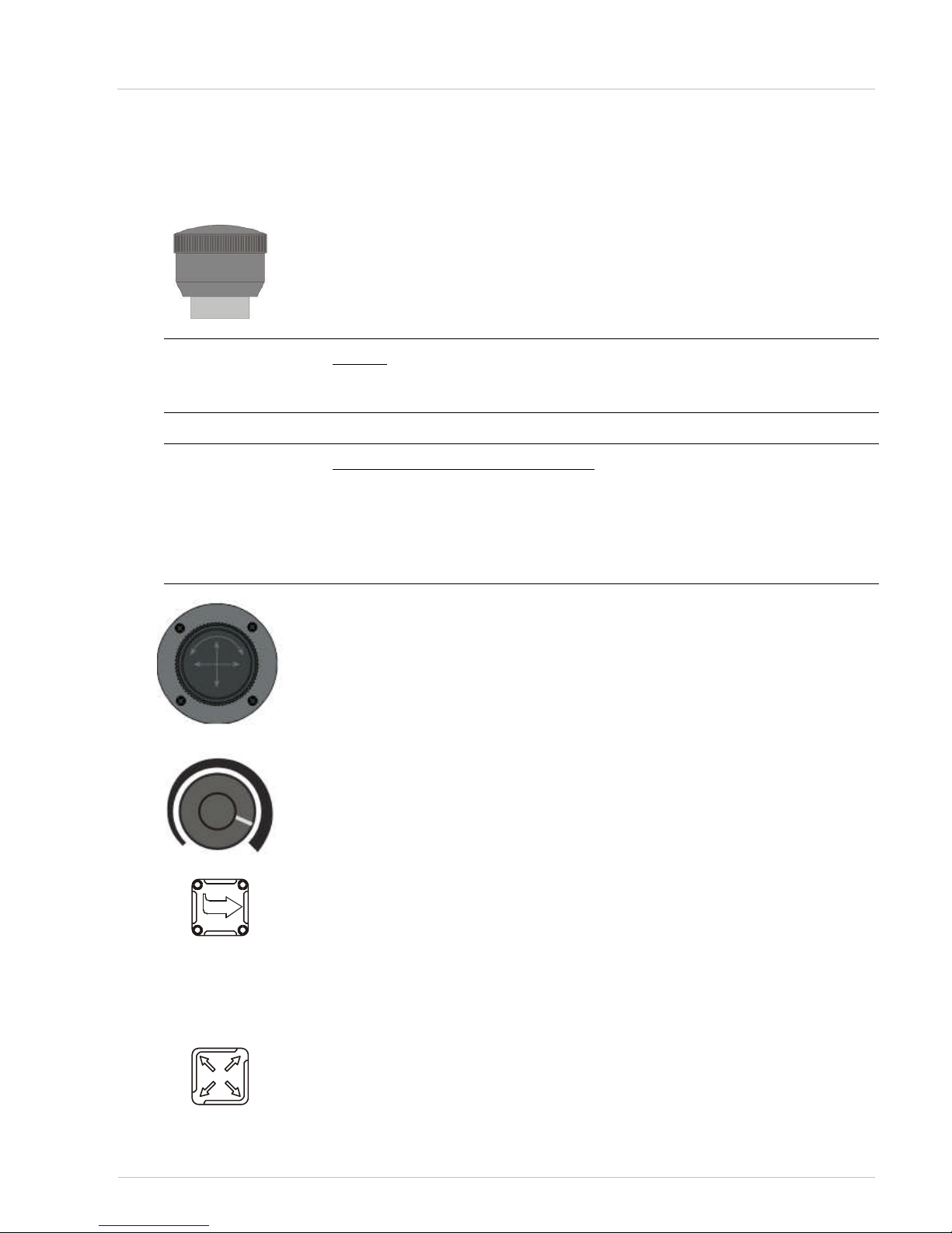
4. Control and display elements
EMERGENCY STOP button
The axis drives can be shut down in emergencies with this pushbutton. All
movements are stopped immediately and the power supply for the servo drives is
cut off. This applies even when an automatic CNC program is run-ning.
NOTE !
Do not use the EMERGENCY STOP button for routinely switching off the axis
drives!
Resetting the EMERGENCY STOP:
Remedy the problem which lead to the button being pressed.
Release the EMERGENCY STOP button.
Switch on the power supply for the servo drives (Servo-ON key).
If necessary, acknowledge fault messages in the software.
The control panel is now ready for operation again.
Joystick
The functioning of the joystick depends on which operating mode is switched on:
With axial control You can traverse a previously activated axis with the
joystick.
With mouse function You can move the mouse pointer on the screen with the
joystick.
Speed control
When the axial control is switched on, moving speed of the machine-axis can be
varied (0-100%).
Changing the alignment and Alignment display
The LEDs shows the orientation of the control panel with respect to the 3
coordinate measuring machine (also refer to Fig. 4.2).
With this pushbutton, you can change the alignment of the control panel with
respect to the 3 coordinate measuring machine independently of the operator’s
workstation. Each time the button is pressed, the alignment is shifted by 90° in the
clockwise direction (also see Chap. 4.4).
Active key
With this key you can switch the axial control on and off. When the axial control is
switched on (the LED Joy shines), you can activate and deacti-vate individual axes
with the aid of the activation keys ("X", "Y", "Z" or "C").

Control Panel - User Manual
4 - Control and display elements
Page 14 of 30 Revision: D Doc.no.: UM-22031
Servo ON
If you press the Servo-ON key, the power supply for the servo drives is switched on.
NOTE !
Extra functions are determined by the respective software adjustment.
Shift key
Pressing this key is the prerequisite for the following functions:
Pressing shift-key and function keys activates second functions.
Activation of brakes ( X, Y, Z, C) depending on Software-
setup.
Left-hand mouse key
The key is always functional even when the axial control is switched on.
The properties/functions of the key (e.g. clicking menus and buttons) de-pend on
the key configuration in the system controller of the PC.
Right-hand mouse key
The key is always functional even when the axial control is switched on.
The properties/functions of the key (e.g. calling up context menus) depend on the
key configuration in the system controller of the PC.
Activation of the X axis
The key is only functional when the axial control is switched on (the LED Joy
shines).
When you press this key, the X-axis is activated. The orange LED at the top right of
the pushbutton now lights up.
Press the key again to deactivate the axis. The LED now goes out.
Pressing shift key and activation key of the X .axis, the respective axis-brake is
switched.
NOTE !
Availability depends on Software-setup.
Activation of the Y axis
The key is only functional when the axial control is switched on (the LED Joy
shines).
When you press this key, the Y-axis is activated. The orange LED at the top right of
the pushbutton now lights up.
Press the key again to deactivate the axis. The LED now goes out.
Pressing shift key and activation key of the Y .axis, the respective axis-brake is
switched.
NOTE !
Availability depends on Software-setup.

Control Panel - User Manual
4 - Control and display elements
Doc.no.: UM-22031 Revision: D Page 15 of 30
Activation of the Z-axis
The key is only functional when the axial control is switched on (the LED Joy
shines).
When you press this key, the Z-axis is activated. The orange LED at the top right of
the pushbutton now lights up (see Chap. 4.2).
Press the key again to deactivate the axis. The LED now goes out.
Pressing shift key and activation key of the Z .axis, the respective axis-brake is
switched.
NOTE !
Availability depends on Software-setup.
Activation of the C-axis (turntable = option)
The key is only functional when the axial control is switched on.
When you press this key, the C-axis is activated. The orange LED at the top right of
the pushbutton now lights up (see Chap. 4.2).
Press the key again to deactivate the axis. The LED now goes out.
Slow/fast – key
With this key you can change over between rapid and crawl traverse rate:
Rapid traverse rate (= LED next to the hare lights up)
Crawl traverse rate (= LED next to the turtle lights up)
NOTE !
The LEDs of the fast/slow button (symbols: hare, turtle) blink when the
base station is connected to the control part and the data packages have
been sent. The blinking rate reflects the quality of connection (i.e. high
blinking rate -> high connection quality; low blinking rate -> poor connection
quality).
-
F1 - F12 key
The functions F1 to F12 depend on the measuring software used in each case.
You can select the previously assigned functions in the software with these keys.
Battery status (HT 400 RC)
3 LEDs indicate energy status of lithium accumulator.

Control Panel - User Manual
5 - Basic functions of the control panel
Page 16 of 30 Revision: D Doc.no.: UM-22031
5. Basic functions of the control panel
The basic functions described here can only be carried out when the con-troller
has been initialised.
Basic setting
When the controller is switched on, the control panel has the following initial
setting:
Axial control is switched off
Rapid traverse rate is switched on
Alignment of the control panel to the measuring machine: Operating position
= facing the Z-axis (also see Fig. 4.2)
NOTE !
Speed-setup (see Chapter 4) must be done manually.
5.1. Powering up HT 400 RC
Switch-on: Press switch-on button.
Battery mode: On-off switch position 1
24 V - Mains: On-off switch position 0
For charging battery or cable use plug in powercable from base-station or external
power-supply.
NOTE !
Base-station is active when WPC 20XX is powered up. With HT 400 RC
switched on, system is .negotiating. to set up a proper link. This will take
approx. 30 sec. And is indicated by a blinking LED of F1-key.

Control Panel - User Manual
5 - Basic functions of the control panel
Doc.no.: UM-22031 Revision: D Page 17 of 30
5.2. Switching on operating mode (mouse function or axial control)
You can change between two operating modes:
axial control (= prerequisite for translating the axes)
mouse function
Switching on axial
control
If you wish to translate/traverse an axis with the joystick, the axial control must
have been previously switched on.
This is how to switch on the axial control::
Press "active key".
The LED Joy shines
NOTE !
If you do not move the joystick for 30 seconds, the axial control is
automatically switched off.
NOTE !
Buttons, menu titles etc. can also be clicked with the mouse keys, when the
axial control is switched on. In this case, the mouse pointer must be moved
to the required button, before the axial control is switched on.
Switching on the
mouse function
Whenever the axial control is switched off, the mouse function is switched on.
When the mouse function is switched on, you can move the mouse pointer around
the screen.
This is how to switch over from the axial control to the mouse
function:
Press "active key".
LED JOY goes out. Axial traverse is switched off and the mouse func-tion is
simultaneously switched on.

Control Panel - User Manual
5 - Basic functions of the control panel
Page 18 of 30 Revision: D Doc.no.: UM-22031
5.3. Moving/traversing axes
This is how to traverse the axes with the control panel:
Switch on the axial control
Activate the required axes: Press the keys for the axes
which you want to traverse ("X", "Y", "Z" or "C").
If an axis is activated, the LED at the top right of the appropriate pushbutton
lights up.
NOTE !
Up to three axes can be simultaneously activated, including either the Zaxis or the C-axis, but not both at the same time. If you switch on a fourth
axis (the C-axis) then the Z-axis will be automatically deactivated. If the Caxis is activated and the Z-axis is switched on, the C-axis is then
automatically deactivated.
NOTE !
If you do not move the joystick for 30 seconds, the axial control is
automatically switched off for safety reasons. In order to traverse the axes,
the axial control must first be restarted.
This is how to control the axis with the joystick:
Traversing X-axis: Deflect joystick to the left/right or forward/reverse
(depending on the measuring machine system).
Traversing Y-axis: Deflect joystick to the left/right or forward/reverse
(depending on the measuring machine system).
Traversing Z-axis: Turn joystick.
o If you turn the joystick clockwise, the axis is moved in a negative Z-
direction (downwards).
o If you turn the joystick anti-clockwise, the axis is moved in a positive Z-
direction (upwards).

Control Panel - User Manual
5 - Basic functions of the control panel
Doc.no.: UM-22031 Revision: D Page 19 of 30
Picture 4 – Traversing Z-axis
Traversing C-axis: Turn joystick.
o If you turn the joystick clockwise, the axis (turntable) also turns
clockwise.
o If you turn the joystick anti-clockwise, the C-axis (turntable) is also
moved anti-clockwise
5.4. Aligning control panel with respect to measuring machine
It is easier to traverse the axes of the measuring machine and thus the measuring
probe, if the joystick and measuring probe move in parallel. For example: If you
move the joystick to the left, the measuring probe also trav-els to the left.
To make this also possible at different operating positions, the alignment of the
control panel with respect to the measuring machine can be changed.

Control Panel - User Manual
5 - Basic functions of the control panel
Page 20 of 30 Revision: D Doc.no.: UM-22031
This is how to change the alignment (taking an LH measuring
machine as an example):
Stand with the HT 400 (RC) control panel at the location, from where you
wish to operate the 3-axis coordinate measuring machine.
Find "your" location in Picture 5
Picture 5 – Alignment of the control panel
This is how to traverse the axes with the control panel:
Keep pressing “Change the alignment” key until the “alignment
display” agrees with “your” position in the diagram.
Check if the axial control is switched on, switch on if necessary.
Activate X- and Y-axes.
Check if the measuring probe moves in the X- or Y-direction, in which
the joystick is deflected.
If the joystick and measuring probe movement agree, then the control panel
alignment has been optimised.

Control Panel - User Manual
5 - Basic functions of the control panel
Doc.no.: UM-22031 Revision: D Page 21 of 30
5.5. Setting/changing rate
The traverse rate of the axes can be set/changed as follows:
Changing over between two basic traverse rates:
o rapid traverse rate
o crawl traverse rate (20% of the rapid traverse rate)
Infinite fine adjustment of the rapid traverse rate. Speed is varied by speed-
control knob.
NOTE !
The traverse rate setting affects all axes.
NOTE !
The traverse rate setting can also be changed while an automatic CNC
program is running. A reduction of the traverse rate is a good idea when
testing a new program, for example. In this case, the CNC traverse rate is
overridden by the traverse rate set at the control panel (traverse rate
override).
This is how to switch over between rapid and crawl traverse rate:
Check the existing setting on the "fast-/slow" key:
o LED next to the hare lights up → Rapid traverse rate is switched on.
o LED next to the turtle lights up → Crawl traverse rate is switched on.
To switch over, press the "fast-/slow" key.
You have now changed the basic traverse rate.
How to change max. traverse-speed:
Faster: Turn knob cw
Slow: Turn ccw
NOTE !
There is an superposition with other speed-settings (hare, turtle, softwaresettings)
The setting is still retained even if:
- the EMERGENCY STOP button is pressed
- the power supply for the servo drives is switched off

Control Panel - User Manual
5 - Basic functions of the control panel
Page 22 of 30 Revision: D Doc.no.: UM-22031
5.6. Switching on the power supply for the servo drives
The power supply for the servo drives can be switched on at the HT 400 (RC)
control panel (= same function as pushbutton at the front panel of the controller).
This is how to switch the power supply:
Press the „Servo-on key“.
The power supply for the servo drives in now switched on.
5.7. Special functions
Press the „Shift key“.plus „Activating-key“
This combination can launch a special function depending on front end
software used. on.
5.8. Battery charge control (HT 400 RC)
Green LED.
100% power.
LED on the right blinks green.
Battery „is being charged“
Yellow LED.
50% power.
Red LED.
10% power.
Red LED blinking.
Approx 0% power..
NOTE !
Red LED blinking will cause an emergency-stop. Charge or replace battery.

Control Panel - User Manual
5 - Basic functions of the control panel
Doc.no.: UM-22031 Revision: D Page 23 of 30
5.9. Recharging battery (HT 400 RC)
Charging of the battery begins as soon as the charging cable is plugged to the
manual terminal. It does not matter whether the appliance is on or not.
Charging takes 6 hours. When the appliance is on the green battery LED blinks
during charging.
NOTE !
Battery capacity sinks to 80% after 350 to 400 charging/discharging cycles.
The battery is to be replaced after 500 charging/discharging cycles.
NOTE !
After a long battery stand-still period (roughly 6 months), the bat-tery
should be subject to 2 charging cycles. Pull out the charging cable after the
1st cycle and then refit -> the 2nd charging cycle then starts.
5.10. Shutdown function of the HT 400 RC control panel
To keep demands down on the battery when not being used for a while, the manual
terminal is automatically shutdown after 30 minutes. The switch-on button must
be pressed before the control panel can be re-operated. With the connection
restored (F1 stops blinking), operations can proceed anew.
NOTE !
While executing a CNC-program this function is deactivated! When ever HT
400 RC is switched off (manually or automati-cally) an error-message
.Emergency-stop. is reported on the screen.
This is the way to switch off the control panel using the sheetcovered keyboard:
Press “Shift key” and then “Servo-on” button in addition.
Control panel is switched off

Control Panel - User Manual
5 - Basic functions of the control panel
Page 24 of 30 Revision: D Doc.no.: UM-22031
5.11. Modified functions of the HT 400 Design control panel
Adjusting mill cutter speed
Only when the mill cutter is active can its speed be changed.
Press the “Active key” to change to the Joy-mode
Press “C” button
Orange LED, top right in the key zone, lights up mill cutter active
Turn the speed adjustment knop to set the speed required
Operating drive coupling and axial brakes.
WARNING
Ensure that the joystick is not extended before pressing the “Servo-on”
button. Otherwise the axes could move in an uncontrolled fashion.
Press “Servo-on” button
The supply voltage for the servo-drives is switched on.
Use the application software (CM) to start the joystick mode.
The X, Y and Z axes are activated (LEDs at the top right in the appro-priate
key zone are illuminated).
The axle drives are engaged and the X, Y and Z brakes are not being applied.
Deactivate the required axies: Press the buttons for the
appropriate axies..
Drive coupling is not applied and the brake of the axis in question is active
(locked). The LED in the respective axis button blinks.
Press the “Shift key” and then the required axis button
as well.
The respective brake is activated and the LED is extinguished.

Control Panel - User Manual
5 - Basic functions of the control panel
Doc.no.: UM-22031 Revision: D Page 25 of 30
This is how to activate the required axis drives:
Press the button for the corresponding axis.
Drives are connected, brakes released and the LEDs light up.
NOTE !
Activating one axis always means an activation of all axes.

Control Panel - User Manual
6 - Maintenance of the control panel
Page 26 of 30 Revision: D Doc.no.: UM-22031
6. Maintenance of the control panel
Wipe the control panel with a slightly damp cloth once a month
- or –
use an anti-static cloth.
Never use benzene or other solvents.

Control Panel - User Manual
7 - Help with faults
Doc.no.: UM-22031 Revision: D Page 27 of 30
7. Help with faults
Fault/malfunction Possible cause Countermeasure/remedy
LED on servo-on button
blinks on power-on. No
activation of servo drives
possible.
Defective Semiconductor. Repair of HT 400 (RC) by
Pantec Engineering AG.
Control panel not
function-ing: LED in
alignment display does
not light up.
Measuring machine controller is not switched on..
Switch on controller
Link between joystick and
controller is faulty.
Check if the plug is connected, connect correctly
if necessary.
Axes (all) cannot be
manually
moved/traversed with the
joystick.
EMERGENCY STOP
button is pressed.
Reset the EMERGENCY
STOP button.
Power supply for servo
drives is not switched on.
Switch on servo drives:
Press "SERVO ON" but-
ton on WPC 20XX.
CNC program is being
executed. The LED Joy
shines.
Wait until the CNC pro-
gram is completed or in-
terrupt it.
The axes have not been
moved for 30 seconds →
device switches the axial
control off (= safety shutdown).
Switch on axial control
again: Press "active key".
Axial control is not
switched on.
Switch on the axial con-
trol: Press "active key".
Knob for seed-attitude is
at the left end. Speed is
near 0.
Knob for seed-attitude
turn to the right.
A particular axis cannot
be manually traversed
with the joystick.
Axis is not activated. Activate the required axis.
Direction of movement of
measuring probe and
joystick do not coincide
(are not parallel)
Operating panel is not
optimally aligned to the
measuring machine..
Change alignment (see
Chap. 4.4).
F1 blinks permanently No link
WPC 20XX switched off Switch on WPC 20XX
Wrong addresses of HT
400 RC and base-station
WP-service must do the
proper setup
HT 400 RC out of range Reduce distance to 2m
Antenna damaged or not
fixed
Repair by Pantec
Engineering AG
The antenna is screened
by a hand or an object..
Stop the screening.
Red LED is blinking, message .Emergency-stop.
appears
Battery low.
Recharge / replace
Plug in cable

Control Panel - User Manual
7 - Help with faults
Page 28 of 30 Revision: D Doc.no.: UM-22031
Fault/malfunction Possible cause Countermeasure/remedy
Mouse pointer cannot be
moved.
The axial control is
switched on.
Switch off axial control →
Mouse function is automatically switched on.
Cable between terminal
socket on the controller
and the mouse socket at
the PC is not plugged in.
Connect the cable.
Mouse is not configured
in the operating system.
Configure mouse and
configure keys as required.
Table 1 – Malfunction table
If you cannot remedy the fault/malfunction with the aid of the malfunction table,
read the notes on faults in the operating manual for the measuring machine or in
the description of the controller.
If you cannot find any help there get in contact with Pantec Engineering AG
customer service. For this purpose, use the ready prepared fault report. This has
been appended the operating manual supplied with your measur-ing machine.

Control Panel - User Manual
8 - Technical data
Doc.no.: UM-22031 Revision: D Page 29 of 30
8. Technical data
HT 400 (Cable
version)
Power supply/DC 24V
Power intake 25 W
Length of the connecting cable: 7 m
Connecting plug 25 pin, socket
Working temperature range +5 … +40 °C
Dimensions (l x B xH) approx. 260 x 115 x 115 mm
Weight (with connecting cable) approx. 1060 g
Table 2 – Technical data on HT 400 control panel
HT 400 RC
(Wireless version)
Power supply/DC 5 / 24V
Power intake max. 6 W
Working temperature range +5 … +40 °C
Dimensions (l x B xH) approx. 260 x 115 x 115 mm
Weight (with battery) approx. 600 g
Range (sith visual contact) max. 10 m
Table 3 – Technical specifications – Control panel HT 400 RC
Base station
Power supply/DC 24V
Power intake 2.5 W
Length of the connecting cable 3 m
Connecting plug 25 pin, socket
Working temperature range +5 … +40 °C
Dimensions (l x B xH) approx. 185 x 105 x 45 mm
Weight (with connecting cable) approx. 1250 g
Table 4 – Technical specifications – Base station HT 400 RC

Control Panel - User Manual
9 - Versionsgeschichte
Page 30 of 30 Revision: D Doc.no.: UM-22031
9. Versionsgeschichte
Version Datum Visum Bemerkungen
A 07.01.02 JORE Building
B 22.04.03 HULO Extensions
C 17.07.03 HULO Extensions
D 18.06.08 HEAN English Version
10. Contact Pantec
With unsolvable Problems, please contact the Pantec Customer Care Service.
PANTEC Engineering AG
Support CMM
Industriering 21
9491 Ruggell
Liechtenstein
mailto: support.cmm@pantec.com
http://www.pantec.com
Phone: +423 377 13 33
Fax: +423 377 13 34
 Loading...