

Page 1
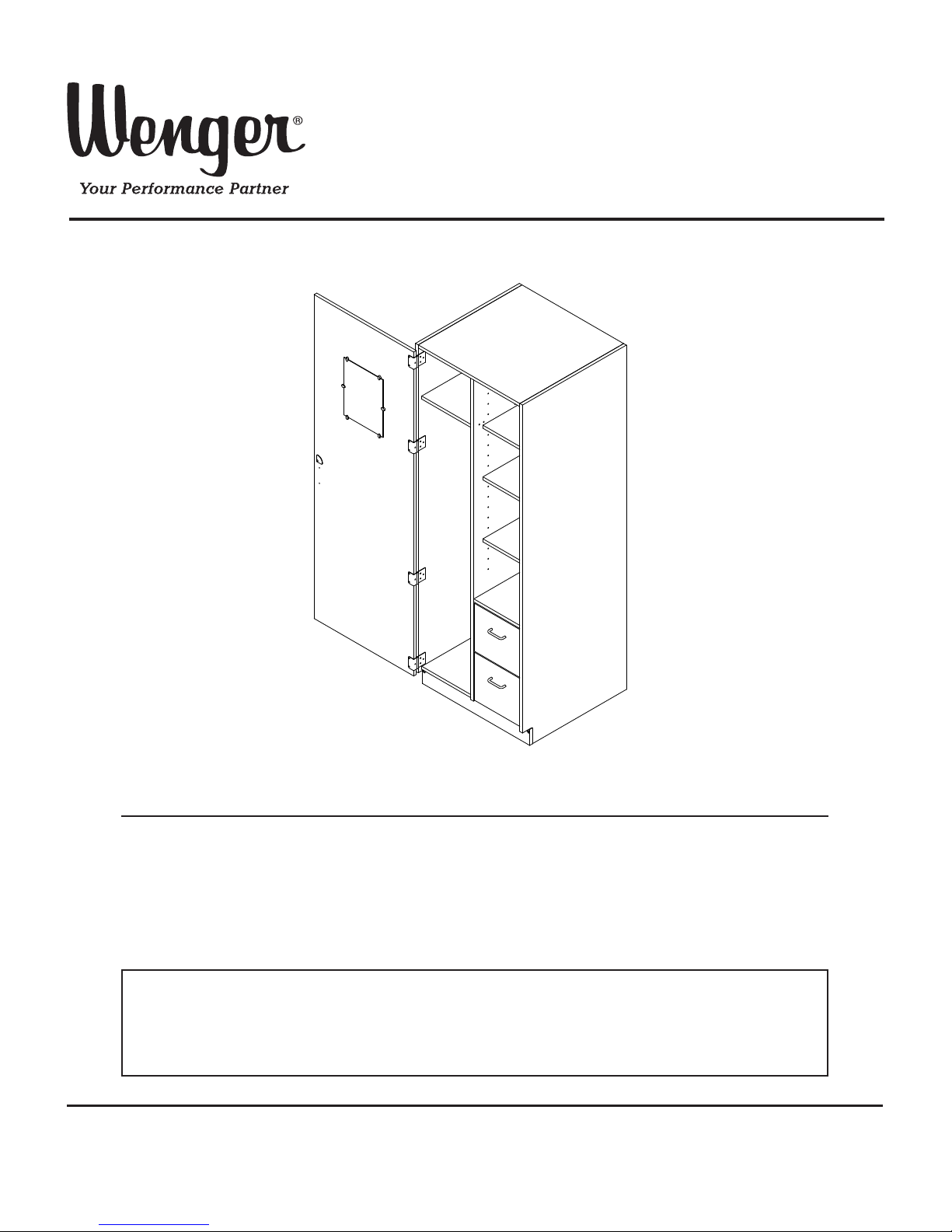
Assembly Instructions
Wardrobe Cabinet
Note: Please read and understand these instructions before assembling the parts.
Note: Remove all items from the shipping cartons and arrange them in a convenient location.
Refer to the illustrations on the following pages.
If you need additional information, contact Wenger Corporation using the information below.
CONTENTS
©Wenger Corporation 2014 Printed in USA 08/14 Part #145V345-04
Wenger Corporation, 555 Park Drive, P.O. Box 448, Owatonna, Minnesota 55060-0448
Questions? Call.....USA: 1-800-4WENGER (493-6437) • Worldwide: 1-507-455-4100 • www.wengercorp.com
Important User Information . . . . . . . . . . . . . . . . . . . . . . . . . . .2
General . . . . . . . . . . . . . . . . . . . . . . . . . . . . . . . . . . . . . .2
Manufacturer . . . . . . . . . . . . . . . . . . . . . . . . . . . . . . . . .2
Intended Use . . . . . . . . . . . . . . . . . . . . . . . . . . . . . . . . .2
Warranty . . . . . . . . . . . . . . . . . . . . . . . . . . . . . . . . . . . . .2
Before You Begin . . . . . . . . . . . . . . . . . . . . . . . . . . . . . . . . . .3
Required Tools . . . . . . . . . . . . . . . . . . . . . . . . . . . . . . . . . . . .3
Fastener Parts List . . . . . . . . . . . . . . . . . . . . . . . . . . . . . . . . .3
Leveling the Cabinets . . . . . . . . . . . . . . . . . . . . . . . . . . . . . . .4
Securing the Cabinet(s) to the Wall . . . . . . . . . . . . . . . . . . . .5
Installing the Shelves . . . . . . . . . . . . . . . . . . . . . . . . . . . . . . .6
File Drawer Removal . . . . . . . . . . . . . . . . . . . . . . . . . . . . . . .7
Page 2

2
IMPORTANT USER INFORMATION
GENERAL
Copyright © 2014 by Wenger Corporation
All rights reserved. No part of the contents of this manual may be reproduced, copied, or transmitted in
any form or by any means including graphic, electronic, or mechanical methods or photocopying,
recording, or information storage and retrieval systems without the written permission of the publisher,
unless it is for the purchaser's personal use.
Printed and bound in the United States of America.
The information in this manual is subject to change without notice and does not represent a commitment
on the part of Wenger Corporation. Wenger Corporation does not assume any responsibility for any
errors that may appear in this manual.
In no event will Wenger Corporation be liable for technical or editorial omissions made herein, nor for
direct, indirect, special, incidental, or consequential damages resulting from the use or defect of this
manual.
The information in this document is not intended to cover all possible conditions and situations that might
occur. The end user must exercise caution and common sense when assembling or installing Wenger
Corporation products. If any questions or problems arise, call Wenger Corporation at 1-800-887-7145.
MANUFACTURER
The Wardrobe Cabinet is manufactured by:
Wenger Corporation
555 Park Drive
Owatonna, MN 55060
1-800-4WENGER (493-6437) • 1-507-455-4100
www.wengercorp.com
INTENDED USE
• This product is intended for indoor use in normal ambient temperature and humidity conditions —
it must not be exposed to prolonged outside weather conditions.
• This product is intended to be assembled and used only as described in these instructions.
WARRANTY
This product is guaranteed free of defects in materials and workmanship for ten full years from
date of shipment. A full warranty statement is available upon request.
Page 3
3
BEFORE YOU BEGIN
• Read the complete assembly procedure before you begin.
• The Wardrobe Cabinet is shipped almost entirely assembled.
To install, level the cabinet and attach the few remaining components as outlined
in these instructions.
• Remove all items from the shipping carton and lay them out approximately in their final position.
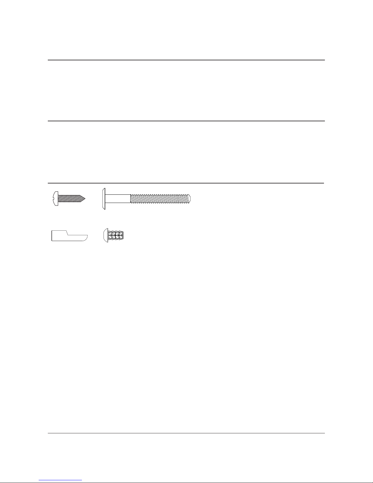
• Remove all items from the hardware bag and determine where all of the fasteners will be used.
Screw Insert,
1
/4-20 x 5/8”
FASTENER PARTS LIST
Note: Hardware Pack may contain extra fasteners.
Screw, SM, PPHD,
ZP, #8 x ⅝
Screw, Mach, ¼-20 x 1.77”
Shelf Support
REQUIRED TOOLS
The following tools must be available to assemble the Wardrobe Cabinet:
• Carpenter’s Level
• Carpenter’s Square
• Plastic Mallet
• Variable Speed Drill (to drive hex socket screws)
• 4mm Hex Drive for Drill
Page 4

4
1. Check the level of the
entire floor where the
cabinets will be
installed. Determine
the highest point of
the floor in that area.
Extend all levelers
until the bottom of the
cabinet will be higher
than the highest point
in the floor.
2. Adjust the levelers on
one side until the front
edges of the cabinet
side panels are plumb
(side-to-side).
3. Measure A and B with a tape
and adjust the front levelers
until A=B (+1/32inch).
4. Adjust both front levelers
equally until the front
edges of the cabinet are
plumb (front-to-back).
5. Recheck that A=B.
Readjust if necessary
(repeat steps 2-4).
If additional cabinets will be installed:
6. Adjust the levelers on the next cabinet so it
will line up with the top of the first cabinet.
7. Repeat steps 2-5 for the second cabinet.
8. Continue in the same manner until all cabinets
are leveled.
LEVELING THE CABINETS
NOTE: Do not try to level the cabinets to match soffits.
NOTE: Do not try to plumb the cabinet to match adjacent walls.
NOTE: For proper door alignment, follow these instructions carefully.
NOTE: To access the levelers, the file drawers must be removed first.
See “File Drawer Removal” before leveling the cabinet.
Page 5

5
SECURING THE CABINET(S) TO THE WALL
NOTE: The following instructions are for standard installations.
For seismic installation instructions, see 145R422.
There are Cabinet Connector Brackets in the hardware bag for securing the cabinets to the
wall surface. Because of the variety of possible wall surfaces, fasteners for attaching the brackets
to the wall are not included. Have your maintenance people recommend an appropriate type for safe,
secure attachment.
NOTE: Make sure all of the cabinets are secured together before attaching them to the back wall.
1. Using the Cabinet Connector Brackets, the cabinets can be tied together
and to the wall surface at the top. The brackets have extra holes:
if the cabinets cannot be positioned tight against the wall,
the bracket can be slid back as much as 2” until it is tight
against the wall surface.
Attach the bracket to the cabinet top using two #8 x5/8” Phillips
Pan Head Screws.
2. Use the necessary fasteners suggested by your maintenance people
to secure the cabinets to the wall.
Cabinet Connector
Bracket
Cabinet Top
Back Wall
Cabinets are unsafe unless
secured as specified.
!
CAUTION
Use methods appropriate to
your wall surface.
!
CAUTION
#8 x 5/8” Phillips
Pan Head Screws
Page 6

6
INSTALLING THE SHELVES
1. Position the Shelf Supports at the desired shelf heights.
The flat edge of the Shelf Support should face up, to match the slots in the
bottom of the shelf.
2. Install the shelves.
3. The larger shelf uses six Shelf Supports and is to be placed at the
bottom of the left side of the cabinet.
Shelf
Support
Page 7

7
FILE DRAWER REMOVAL
1. Extend the file drawers so that the Release Levers are visible.
Slide the Release Levers either up or down and the file drawers can be removed by pulling outward.
Now the cabinet can be leveled according to “Leveling the Cabinets”.
2. Re-install the file drawers by aligning the rails that are attached to the file drawer with the rails
that are attached to the cabinet.
Slide the drawer back until the Release Lever snaps into position.
Release Lever
(on both sides of drawers)
Page 8

8
This page is intentionally blank.
 Loading...