

Page 1

Assembly Instructions
Violin/Viola Storage Rack
CONTENTS
Safety Precautions . . . . . . . . . . . . . . . . . . . . . . . . . . . . . . . . . . 2
Warranty . . . . . . . . . . . . . . . . . . . . . . . . . . . . . . . . . . . . . . . . . . 2
Important User Information. . . . . . . . . . . . . . . . . . . . . . . . . . . . 3
General. . . . . . . . . . . . . . . . . . . . . . . . . . . . . . . . . . . . . . . 3
Manufacturer . . . . . . . . . . . . . . . . . . . . . . . . . . . . . . . . . . 2
Intended Use . . . . . . . . . . . . . . . . . . . . . . . . . . . . . . . . . . 2
Before You Begin . . . . . . . . . . . . . . . . . . . . . . . . . . . . . . . . . . . 3
Required Tools . . . . . . . . . . . . . . . . . . . . . . . . . . . . . . . . . . . . . 4
Fastener Parts List . . . . . . . . . . . . . . . . . . . . . . . . . . . . . . . . . . 4
Parts List. . . . . . . . . . . . . . . . . . . . . . . . . . . . . . . . . . . . . . . . . . 5
Assembly . . . . . . . . . . . . . . . . . . . . . . . . . . . . . . . . . . . . . . . . 6-9
Operation . . . . . . . . . . . . . . . . . . . . . . . . . . . . . . . . . . . . . . . . 10
Replacement Parts List. . . . . . . . . . . . . . . . . . . . . . . . . . . . . . 11
Please read and understand these Assembly Instructions before working with or using the
Violin/Viola Storage Rack.
If you need additional information about the Violin/Viola Storage Rack, contact Wenger Corporation
using the information below.
©Wenger Corporation 2010 Printed in China 02/10 Part #148H056-02
Wenger Corporation, 555 Park Drive, P.O. Box 448, Owatonna, Minnesota 55060-0448
Questions? Call.....USA: (800) 733-0393 • International (call collect): (507) 455-4100 • www.wengercorp.com
Page 2
SAFETY PRECAUTIONS
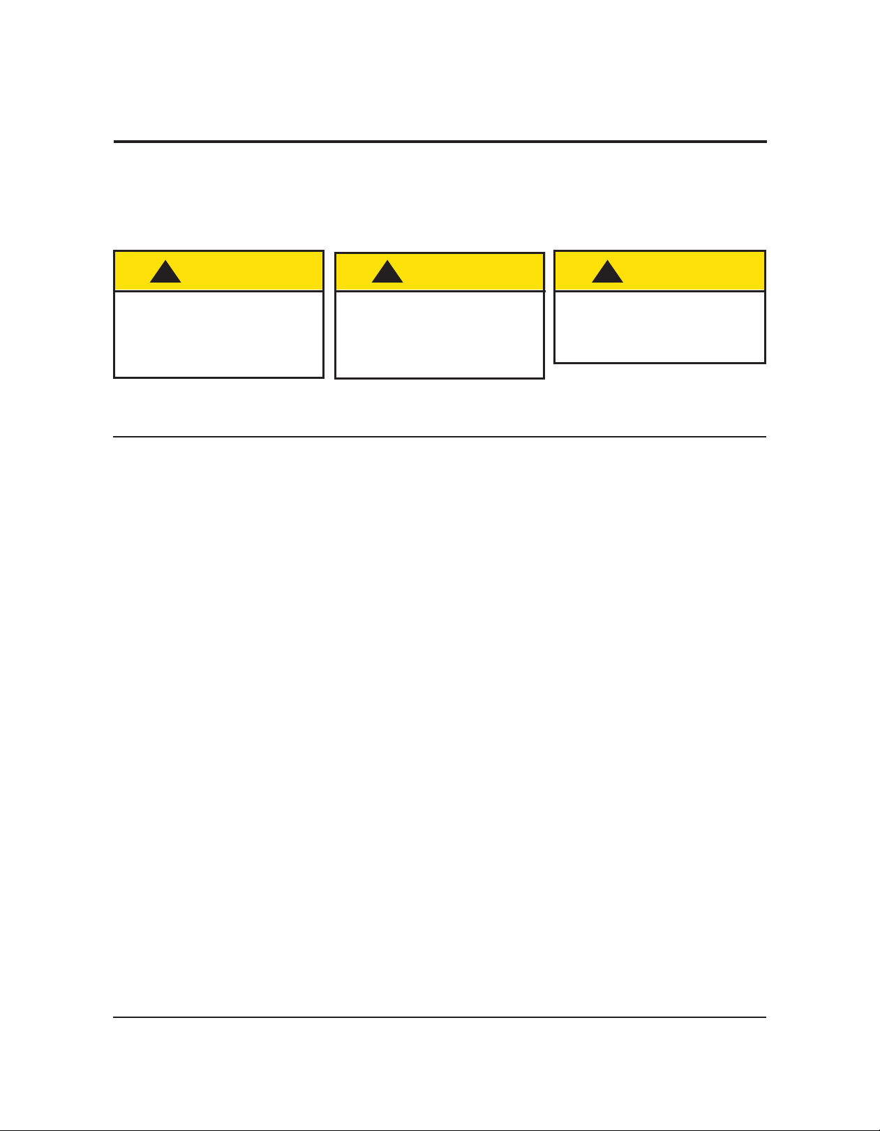
Throughout this manual you will find cautions and warnings which are defined as follows.
• WARNING means that failure to follow the instruction may result in serious injury or death.
• CAUTION means that failure to follow the instruction may result in serious injury or damage to
property.
Read all of these safety instructions before setting up the Violin/Viola Storage Rack components.
!
CAUTION
Make sure that anyone
working on the Violin/Viola
Storage Rack has read and
understands this manual.
!
CAUTION
It is unsafe for only one
person to assemble or move
the Violin/Viola Storage Rack.
!
CAUTION
Eye protection is required
when assembling the
Violin/Viola Storage Rack.
WARRANTY
The Violin/Viola Storage Racks are guaranteed free of defects in materials and workmanship for
five full years.
Our guarantee assures you of either a full refund or repair or replacement of the defective materials or
workmanship without charge, at the discretion of our Customer Service Department. Just call a
Customer Service Representative at 1-800-887-7145 and state the reason you are dissatisfied. If a
product return is necessary, your representative will issue a return authorization. This is your sole
remedy for breach of this warranty.
Should you have a question or problem with any Wenger product, don’t hesitate to call, even if the
product is past warranty. It’s important to us that all our customers be satisfied.
This is the sole warranty made by Wenger. Wenger disclaims all other warranties, including the
warranties of merchantability and fitness for a particular purpose, as well as all liability for incidental,
consequential, special, and indirect damage. Wenger liability for direct damages shall be limited to the
amount you paid for the product involved. Wenger reserves the right to make product changes without
obligation to incorporate such changes into products previously sold.
Some states do not allow the exclusion or limitation of damages or warranties, so the above may not
apply to you. This warranty gives you specific legal rights. You may also have other rights which vary
from state to state.
2
Page 3

IMPORTANT USER INFORMATION
GENERAL
Copyright©2009 by Wenger Corporation
All rights reserved. No part of the contents of this manual may be reproduced, copied, or transmitted in
any form or by any means including graphic, electronic, or mechanical methods or photocopying,
recording, or information storage and retrieval systems without the written permission of the publisher,
unless it is for the purchaser's personal use.
Printed and bound in the China.
The information in this manual is subject to change without notice and does not represent a commitment
on the part of Wenger Corporation. Wenger Corporation does not assume any responsibility for any
errors that may appear in this manual.
In no event will Wenger Corporation be liable for technical or editorial omissions made herein, nor for
direct, indirect, special, incidental, or consequential damages resulting from the use or defect of this
manual.
The information in this document is not intended to cover all possible conditions and situations that might
occur. The end user must exercise caution and common sense when assembling or installing Wenger
Corporation products. If any questions or problems arise, call Wenger Corporation at 1-800-733-0393.
MANUFACTURER
The Violin/Viola Storage Racks are manufactured for:
Wenger Corporation
555 Park Drive
Owatonna, MN 55060
1-507-455-4100 • 1-800-733-0393 www.wengercorp.com
INTENDED USE
• This product is intended for indoor use in normal ambient temperature and humidity conditions — it
must not be exposed to prolonged outside weather conditions.
• This product is intended to be assembled only as described in these instructions.
3
Page 4
BEFORE YOU BEGIN
• Read the complete assembly procedure before you begin.
• Open both large cartons, and compare the parts to the “Replacement Parts List” listed below.
Note that the Left and Right End Panels (2) are identical
(until you attach Caster Brackets (1) to them).
• Fasteners and loose parts are packed in the Hardware Pack.
REQUIRED TOOLS
The following tools must be available to assemble the Violin/Viola Storage Rack:
• Plastic Mallet
• Phillips-Head Screwdriver
• Variable Speed Drill (to drive hex socket screws)
• 5/32” Hex Insert Bit (supplied)
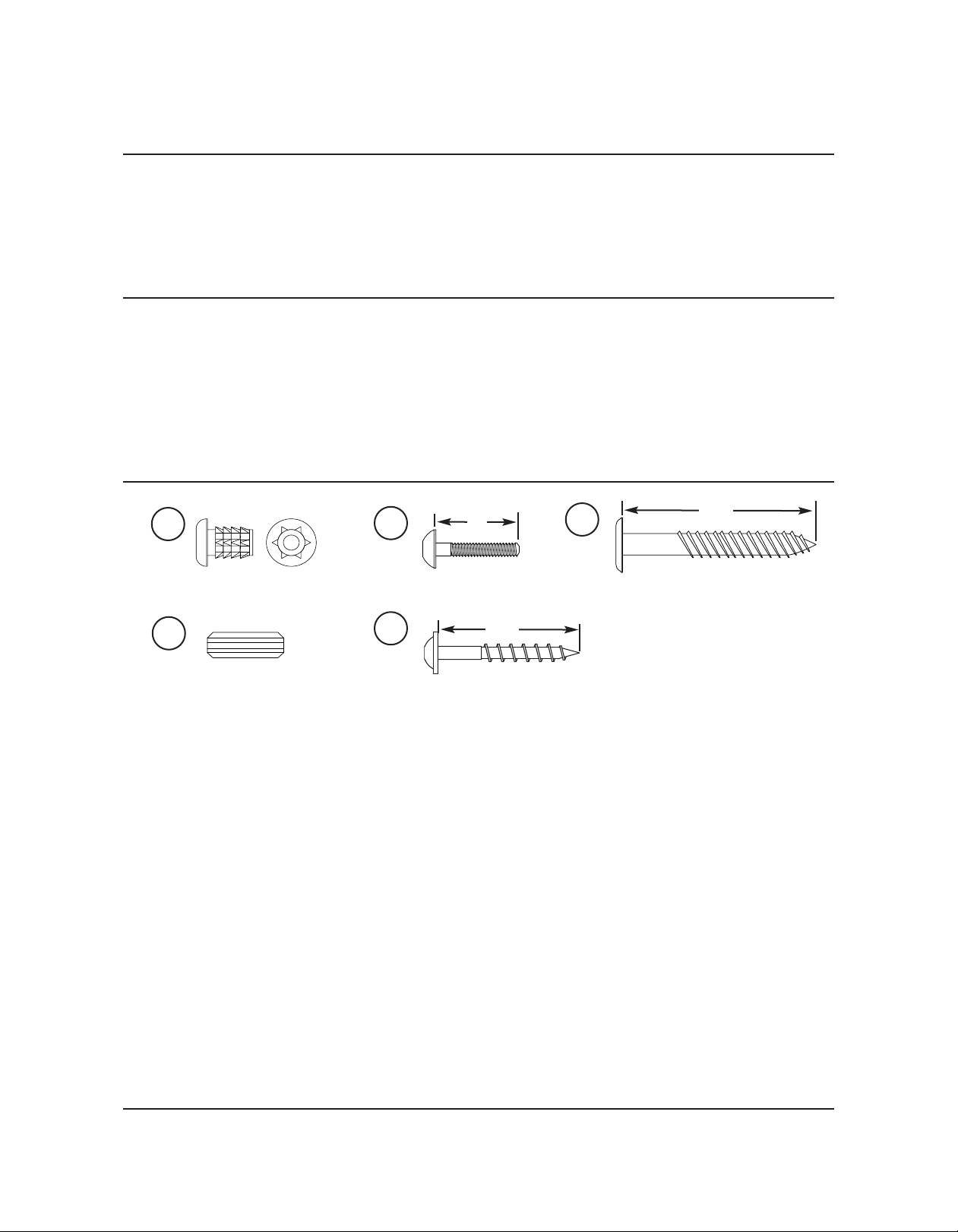
FASTENER PARTS LIST
3
Insert Nut
6
Wood Dowel
4
Truss Head Screw
16
• Some quantities vary depending on the model.
• Extra hardware can be discarded.
3
/4”
11/4”
Wood Screw
5
Hex Socket Lag Screw
2”
4
Page 5

PARTS LIST
• Parts appear in 3D to provide visual of pre-drilled hole placement.
• Pre-drilled holes vary by size and model of unit.
• Some quantities vary depending on the model.
• Extra hardware can be discarded.
10
9
12
14
11
15
2
13
1
18
17
8
7
Item Qty Description Item Qty Description
1 4 Bracket, caster 10 2 Panel, top, cross
2 2 Panel, end, right and left 11 2 Panel, Top Neck Support
3 8 Nut, insert 12 1 Panel, Base, Middle Front
4 8 Screw, truss-head, 3/4" 13 6 Panel, divider
5 60 Screw, Lag, hex socket, 2" 14 2 Panel, base, rear
6 28 Dowel, wood 15 2 Panel, base, lower support
7 2 Caster, locking 16 14 Wood Screw, 1 1/4"
82Caster, non-locking 17 14 Peg, divider
9 1 Panel, base, lower front 18 12 round, spacer
5
Page 6

ASSEMBLY
1. Assemble both the Upper and Lower Base Supports.
a. Insert one Wood Dowel (#6) into each Divider Panel (#13). (Detail A)
b. Secure the Divider Panels with Dowels to the Rear base Panel (#14) using three 2" Hex
Socket Lag Screws (#5) on each assembly. (Detail A)
Important Note: If you experience problems with alignment during assembly, dowels may be
removed and not used.
6
13
Detail A
5
14
c. Insert four Wood Dowels (#6) into each Lower Support Base Panel (#15)
d. Secure Lower Support Base Panel with Dowels to the Rear Base Panel (#14) using four 2"Hex
Socket Lag Screws (#5) on each assembly. (Detail B)
14
6
15
5
Detail B
e. Pound in Insert Nuts (#3) as shown in Detail C. Two on each ends of the Lower Front Base
Panel (#9).
f. Attach Caster Brackets (#1) to the inside outer Lower Front
Base (#9) corners as shown with
9
3
Detail C
3
/4" Truss Head Screws (#4).
(Detail D)
6
Detail D
4
1
Page 7

ASSEMBLY (CONTINUED)
g. Insert one Wood Dowel (#6) into each Divider Panel (#13).
h. Insert each Round Spacer (#18) into the Rear Base Panel (#14)
i. Secure the Divider Panel with Wood Dowel (#6) to the Lower Front Base Panel (#9) and Upper
Front Base Panel (#12) using three 2" Hex Socket Lag Screws (#5) on each assembly.
(Detail E)
2. Repeat step 1 to assemble the middle base support.
For Lower
9
For Middle
6
12
5
Detail E
18
14
3. Pound in Insert Nuts (#3) two on each outside rear corner of
the End Panels (#2). (Detail F)
2
13
3
Detail F
3
4. Attach Caster Brackets (#1) to the inside rear corners
of the End Panels (#2) as shown with
3
/4" Truss Head Screws (#4). (Detail G)
7
Detail G
2
1
4
4
1
Page 8

ASSEMBLY (CONTINUED)
5. Assemble both the Upper and Lower Neck Supports:
a. Insert Divider Pegs (#17) into Neck Support Top
Panel (#11) and secure with 1
(#16). (Detail H)
b Insert four Wood Dowels (#6) into the edge of
the Cross Board with Pegs (#11). (Detail I)
1
/4" Wood Screw
11
16
c. Secure the Upper Support Cross
Board (#10) to the Cross Board with
Pegs (#11) using four 2” Hex Socket
Lag Screws (#5). (Detail I)
6
10
5
Detail I
11
6. Attach the Lower Base Support Assembly and one
Neck Support to the End Panels (#2) using eight Hex Socket Lag
Screws (#5) per side. (Detail J).
17
Detail H
Wood Dowel is
to the outside.
2
5
Lower Support
Base Assembly
8
Lower Neck
Support Assembly
Detail J
Page 9

ASSEMBLY
(CONTINUED)
7. Attach the Middle Support Assembly and the Upper Neck Support Assembly to the End Panels (#2)
using eight Hex Socket Lag Screws (#5) per side. (Detail K)
Upper Neck
5
Middle Support
Assembly
Detail K
Support Assembly
2
8. Snap the four Casters into the Caster Brackets.
The two Locking Casters (#7) attach to the front
and the two Non-locking Casters (#8) attach to the back.
(Detail L)
8
Detail L
7
8
9
Page 10

OPERATION
Before placing instruments on the mobile rack, be sure the casters are in the locked position.
Unlock the casters to move the rack. Two people are recommended to move the rack.
Move the rack slowly and carefully making sure the instruments stay in place during transport.
10
Page 11

REPLACEMENT PARTS
Item Qty Description Item Qty Description
1 4 Bracket, caster 10 2 Panel, top, cross
2 2 Panel, end, right and left 11 2 Panel, Top Neck Support
3 8 Nut, insert 12 1 Panel, Base, Middle Front
4 8 Screw, truss-head, 3/4" 13 6 Panel, divider
5 60 Screw, Lag, hex socket, 2" 14 2 Panel, base, rear
6 28 Dowel, wood 15 2 Panel, base, lower support
7 2 Caster, locking 16 14 Wood Screw, 1 1/4"
82Caster, non-locking 17 14 Peg, divider
9 1 Panel, base, lower front 18 12 round, spacer
2
13
10
14
12
11
18
2
10
7
16
9
17
14
8
Front View
15
1
4
8
11
17
10
7
5
Back View
8
3
11
 Loading...