

Page 1
Installation Instructions
Studio®Makeup Station
Drawer Option
Studio Makeup Station with Drawer Option
CONTENTS
Fasteners and Part List ............................................................................................................................................2
Fasteners..........................................................................................................................................................2
Part List ............................................................................................................................................................2
Required Tools..........................................................................................................................................................2
Installation.................................................................................................................................................................3
Before Starting the Assembly ...........................................................................................................................3
Install the Drawer .............................................................................................................................................3
Warranty ...................................................................................................................................................................7
Note: Please read and understand the Studio Makeup Station Drawer Option Installation
Instructions before assembling the parts.
Note: Refer to the illustrations on the following pages. If you need additional information about
your Studio Makeup Station Drawer Option, write, email, or telephone Wenger Corporation
at the number or address below.
Note: Document each Studio Makeup Station Drawer key number or keep a master key for each
Drawer Lock. Without this information keys cannot be replaced, because each Studio
Makeup Station Drawer is keyed differently.
©Wenger Corporation 2014 Printed in USA 02/14 Part #187A144-02
Wenger Corporation, 555 Park Drive, P.O. Box 448, Owatonna, Minnesota 55060-0448
Questions? Call.....USA: 800-4WENGER (493-6437) • Worldwide: 1-507-455-4100 • www.wengercorp.com
Page 2
FASTENERS AND PART LIST
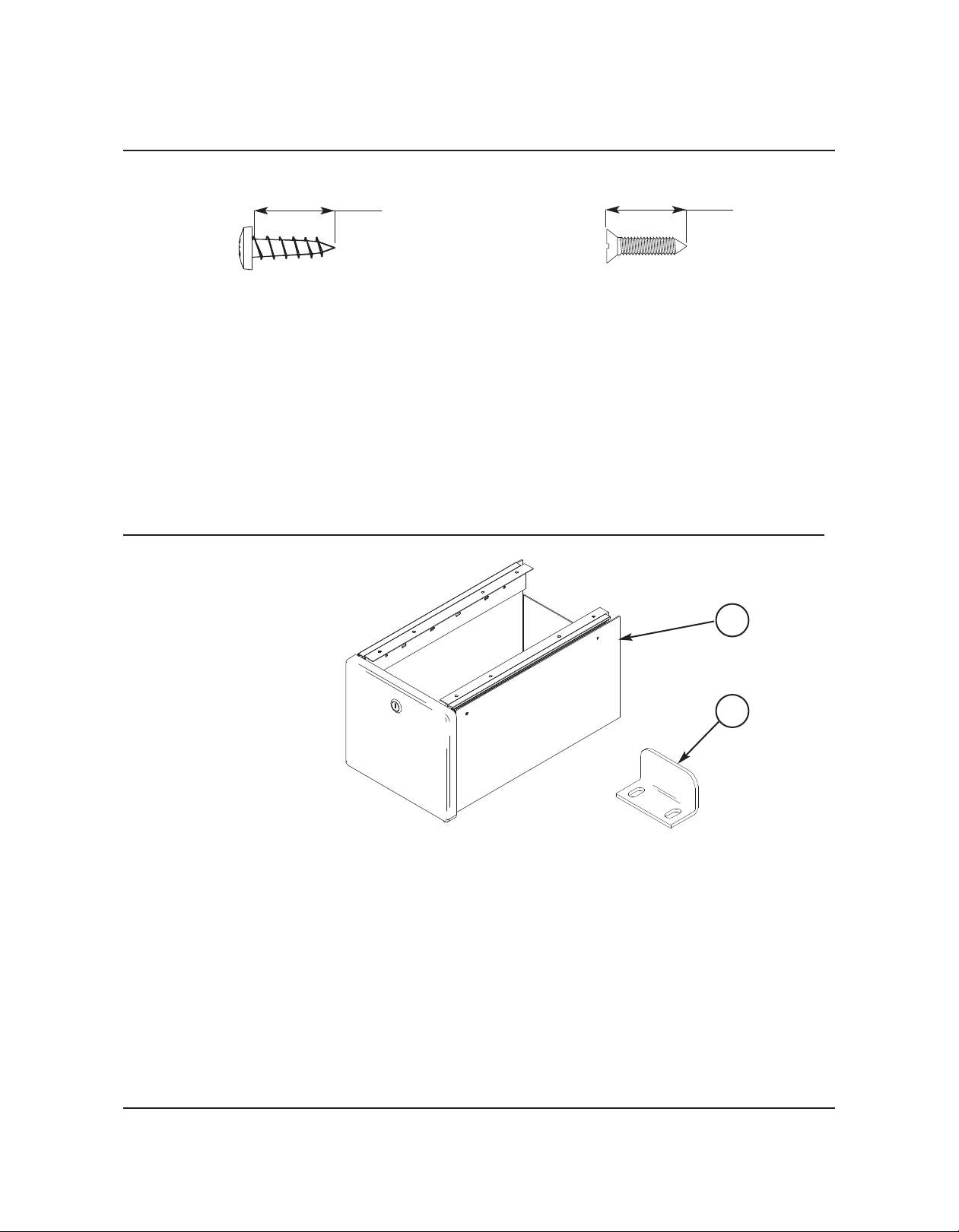
FASTENERS
3/4-inch
Phillips Pan Head Sheet Metal Screw, 10x3/4-inch
PART LIST
Item Qty. Description
1 1 Drawer
2 1 L-Bracket**
3 9 Phillips Pan Head Sheet Metal Screw, 10x3/4-inch **
4 3 Phillips Flat Head Sheet Metal Screw, #8x3/4-inch **
5 1 Lock Assembly Key Set (not shown) **
** Contained in the Hardware Kit Bag
3/4-inch
Phillips Flat Head Sheet Metal Screw, #8x3/4-inch
1
2
2
Page 3

REQUIRED TOOLS
The installer must supply the tool shown below (a phillips screwdriver).
Phillips Screwdriver
3
Page 4

INSTALLATION
BEFORE STARTING THE ASSEMBLY
Before installing the Studio Makeup Station Drawer Option, do the following.
1. Read and understand this entire installation instruction.
2. Open the shipping container and make sure that it contains a Drawer and a Hardware Pack with
one L-Bracket, a set of keys for the Lock, 9 Pan Head Screws and 3 Flat Head Screws.
3. Remove the Keys from the Hardware Pack and place one key in a safe place.
Note: Document each Studio Makeup Station Drawer key number or keep a master key for each
Drawer Lock. Without this information keys cannot be replaced, because each Studio Makeup
Station Drawer is keyed differently.
Danger! Never remove the Counter to install the Drawer. Removing the Counter exposes live
electrical wires. Contact with these wires can result in electrical shock, serious injury,
death, or damage to property.
Warning: Always wear safety glasses when installing the Studio Makeup Station Drawer Option.
Failure to observe this precaution can result in serious injury.
INSTALL THE DRAWER
1. Locate the ten pre-drilled pilot holes on the bottom-right and bottom-left side of the Counter.
2 Choose the right or left side of the Counter for the Drawer assembly.
Pilot Holes
Counter Bottom Surface
3. Remove both Drawer Glide Slide Assemblies from the Drawer as follows.
a. Pull a Drawer Glide Slide Assembly
outward as far as it will move.
b. Depress the Drawer Disconnect
Lever and remove the Drawer Glide
Drawer Glide Slide
Assembly
Slide Assembly from the Drawer
Stationary Glide.
c. Set the Drawer Glide Slide Assembly
aside.
d. Remove the other Drawer Glide Slide
Assembly by repeating steps a, b,
and c.
Drawer Glide
Disconnect Lever
Drawer Stationary Glide
Drawer
4
Page 5

INSTALLATION CONTINUED
INSTALL THE DRAWER C
ONTINUED
4. Align the mounting holes of a Drawer Glide Slide Assembly to a set of Pilot Holes on the bottom
side of the Counter. Make sure that the Bracket Flange faces the Main Frame and that the
Glide opens outward.
Main Frame
!
WARNING
Do not remove the
Counter to install
the Drawer. Serious
electrical shock or
death can result.
Counter
Bracket Flange
Drawer Glide Slide Assembly
5. Using a phillips screwdriver,
attach each Drawer Glide
Slide Assembly to the
Counter with four Pan Head
Screws.
Pan Head Screw, 10x3/4-inch
Drawer Glide Slide Assembly
Caution: Tighten the Pan Head Screws only enough to be snug. Over tightening can strip the
threads in the Counter
6. Attach the L-Bracket to the Counter by screwing two Flat Head Screws, #8x3/4-inch, into the two
Lock Bracket Pilot Holes. Make sure that the flange faces the outside edge of the Counter.
Note: The L-Bracket may need to be adjusted in or out to fully engage the lock.
Lock Bracket Pilot Hole
Note: The L-Bracket Flange faces
the outside edge of the
Counter
L-Bracket
Flat Head Screw, #8x3/4-inch
5
Page 6

INSTALLATION CONTINUED
INSTALL THE DRAWER C
ONTINUED
7. Insert the Drawer into the Drawer Glide Slide Assemblies.
Drawer
Studio Makeup Station
6
Page 7

WARRANTY
The Studio Makeup Station Drawer Option is guaranteed free of defects in materials and workmanship
for five full years.
Our guarantee assures you of either a full refund or repair or replacement of the defective materials or
workmanship without charge, at the discretion of our Customer Service Department. Just call a
Customer Service Representative at 1-800-887-7145 and state the reason you are dissatisfied. If a
product return is necessary, your representative will issue a return authorization. This is your sole
remedy for breach of this warranty.
Should you have a question or problem with any Wenger product, don’t hesitate to call, even if the
product is past warranty. It’s important to us that all our customers be satisfied.
This is the sole warranty made by Wenger. Wenger disclaims all other warranties, including the
warranties of merchantability and fitness for a particular purpose, as well as all liability for incidental,
consequential, special, and indirect damage. Wenger liability for direct damages shall be limited to the
amount you paid for the product involved. Wenger reserves the right to make product changes without
obligation to incorporate such changes into products previously sold.
Some states do not allow the exclusion or limitation of damages or warranties, so the above may not
apply to you. This warranty gives you specific legal rights. You may also have other rights which vary
from state to state.
7
Page 8

This page is intentionally blank.
8
 Loading...