

Page 1
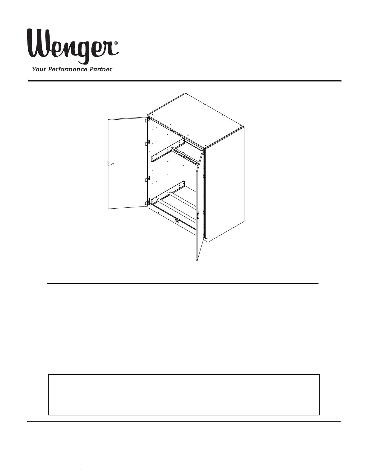
Assembly/Installation Instructions
Stringed Instrument
Storage Cabinet (#42)
Note: Please read and understand these instructions before assembling the parts.
Note: Remove all items from the shipping cartons and arrange them in a convenient location.
Refer to the illustrations on the following pages.
If you need additional information, contact Wenger Corporation using the information below.
CONTENTS
©Wenger Corporation 2014 Printed in USA 08/14 Part #250A700-03
Wenger Corporation, 555 Park Drive, P.O. Box 448, Owatonna, Minnesota 55060-0448
Questions? Call.....USA: 1-800-4WENGER (493-6437) • Worldwide: 1-507-455-4100 • www.wengercorp.com
Important User Information. . . . . . . . . . . . . . . . . . . . . . . . . . . . 2
General. . . . . . . . . . . . . . . . . . . . . . . . . . . . . . . . . . . . . . . 2
Manufacturer . . . . . . . . . . . . . . . . . . . . . . . . . . . . . . . . . . 2
Intended Use . . . . . . . . . . . . . . . . . . . . . . . . . . . . . . . . . . 2
Warranty . . . . . . . . . . . . . . . . . . . . . . . . . . . . . . . . . . . . . . 2
Safety Precautions . . . . . . . . . . . . . . . . . . . . . . . . . . . . . . . . . . 3
Before Installation. . . . . . . . . . . . . . . . . . . . . . . . . . . . . . . . . . . 3
Overview. . . . . . . . . . . . . . . . . . . . . . . . . . . . . . . . . . . . . . 3
Before You Begin . . . . . . . . . . . . . . . . . . . . . . . . . . . . . . . 3
Required Tools . . . . . . . . . . . . . . . . . . . . . . . . . . . . . . . . . . . . . 4
Fastener Parts List . . . . . . . . . . . . . . . . . . . . . . . . . . . . . . . . . . 4
Assembly . . . . . . . . . . . . . . . . . . . . . . . . . . . . . . . . . . . . . . . . . 5
Operation . . . . . . . . . . . . . . . . . . . . . . . . . . . . . . . . . . . . . . . . . 7
To Level Cabinets . . . . . . . . . . . . . . . . . . . . . . . . . . . . . . . . . . . 9
To Attach Full-Length Wood Doors. . . . . . . . . . . . . . . . . . . . . 10
To Attach Full-Length Grille Doors . . . . . . . . . . . . . . . . . . . . . 11
To Secure Cabinets . . . . . . . . . . . . . . . . . . . . . . . . . . . . . . . . 12
To Secure Cabinets Together. . . . . . . . . . . . . . . . . . . . . 12
To Secure Cabinets to the Back Wall. . . . . . . . . . . . . . . 13
To Secure Cabinets Back to Back . . . . . . . . . . . . . . . . . 14
AcoustiCabinet Backing Attachment. . . . . . . . . . . . . . . . . . . . 15
To Secure the AcoustiCabinet . . . . . . . . . . . . . . . . . . . . . . . . 15
To Secure AcoustiCabinets Together . . . . . . . . . . . . . . . 16
To Install Cover Panels. . . . . . . . . . . . . . . . . . . . . . . . . . 17
To Secure Cabinets to the Wall . . . . . . . . . . . . . . . . . . . 20
Storage Cabinet Maintenance . . . . . . . . . . . . . . . . . . . . . . . . 24
Cleaning . . . . . . . . . . . . . . . . . . . . . . . . . . . . . . . . . . . . . 24
Humidity Control . . . . . . . . . . . . . . . . . . . . . . . . . . . . . . . 24
Page 2

2
IMPORTANT USER INFORMATION
GENERAL
Copyright © 2014 by Wenger Corporation
All rights reserved. No part of the contents of this manual may be reproduced, copied, or transmitted in
any form or by any means including graphic, electronic, or mechanical methods or photocopying,
recording, or information storage and retrieval systems without the written permission of the publisher,
unless it is for the purchaser's personal use.
Printed and bound in the United States of America.
The information in this manual is subject to change without notice and does not represent a commitment
on the part of Wenger Corporation. Wenger Corporation does not assume any responsibility for any
errors that may appear in this manual.
In no event will Wenger Corporation be liable for technical or editorial omissions made herein, nor for
direct, indirect, special, incidental, or consequential damages resulting from the use or defect of this
manual.
The information in this document is not intended to cover all possible conditions and situations that might
occur. The end user must exercise caution and common sense when assembling or installing Wenger
Corporation products. If any questions or problems arise, call Wenger Corporation at 1-800-887-7145.
MANUFACTURER
The Stringed Instrument Storage Cabinet (#42) is manufactured by:
Wenger Corporation
555 Park Drive
Owatonna, MN 55060
1-800-4WENGER (493-6437) • 1-507-455-4100
www.wengercorp.com
INTENDED USE
• This product is intended for indoor use in normal ambient temperature and humidity conditions —
it must not be exposed to prolonged outside weather conditions.
• This product is intended to be assembled and used only as described in these instructions.
WARRANTY
This product is guaranteed free of defects in materials and workmanship for ten full years from
date of shipment. A full warranty statement is available upon request.
Page 3
3
SAFETY PRECAUTIONS
Make sure anyone working
on the Storage Cabinets has
read and understands this
manual.
!
CAUTION
Failure to comply with
Warnings and Cautions in
this document can result in
damage to property or
serious injury.
!
CAUTION
Always observe and comply
with the Warnings and
Cautions posted on the
system equipment.
!
CAUTION
It is unsafe for only one
person to assemble or move
the Storage Cabinets.
!
CAUTION
Make sure the Cabinets are
securely attached to walls or
floor after assembly is
complete.
!
CAUTION
Throughout this manual you may find CAUTIONS and WARNINGS they are defined as follows:
• WARNING; failure to follow the instruction may result in serious injury or death.
• CAUTION; failure to follow the instruction may result in serious injury or damage to property.
Read all of these safety instructions before assembling and installing the Storage Cabinets.
OVERVIEW
It is suggested that the Storage Cabinets are set up in a space that is large enough (approximately 25' x 25')
to safely handle the cartons, pieces, finished cabinets, and dunnage.
Inspect the condition of the wall and floor where the cabinets will be located. If the wall is not straight,
establish a reference line so the fronts of all cabinets will line up. Also, determine the highest point on
the floor, which will establish the leveled height of each row of cabinets.
Build only one cabinet at a time, to avoid intermixing parts. Build each according to the instructions in
this manual for the specific model. Do not start installing doors until all cabinets are assembled and in
their final location, leveled, and bolted to adjacent walls and cabinets.
After all cabinets are in place, distribute the door cartons and door hardware sets to each cabinet.
Assemble and hang the doors one at a time according to the instructions. Then clean off any
fingerprints, dirt, and dust, using a clean rag and Fantastic (or comparable) spray cleaner or acetone.
BEFORE YOU BEGIN
Keep the Storage Cabinet Packing List with the cabinet, use for reference until the unit is completely
assembled.
• Read the complete assembly procedure before beginning to assemble the cabinet.
• Hardware packs may contain extra fasteners that will not be required on your cabinet.
• Because of the variety of possible wall surfaces, they are not included.
Have your maintenance personnel recommend an appropriate type for safe, secure attachment
and have the fasteners available before assembling the cabinet.
• At least two people (preferably four) are required to assemble the cabinet and set it upright.
BEFORE INSTALLATION
Page 4
4
• Plastic Mallet
• Phillips Head Screwdriver
• Standard Screwdriver
• Open-End Wrench,
7/16
"
• Open-End Wrench,
3
/8"
• Open-End Wrench,
1
/2"
• Allen Wrench,
5
/
3
2
"
• Open-End Wrench,
1
/4" or 1/4" socket
• 4-mm Hex Drive for Drill (supplied)
• Carpenter’s Level
• Tape Measure
• Carpenter’s Square
• Variable Speed Electric Drill (to drive Hex Socket
Screws)
• Utility Knife
NOTE: To save assembly time, it is recommended to
have more than one of each ty
pe of
screwdriver on hand.
REQUIRED TOOLS
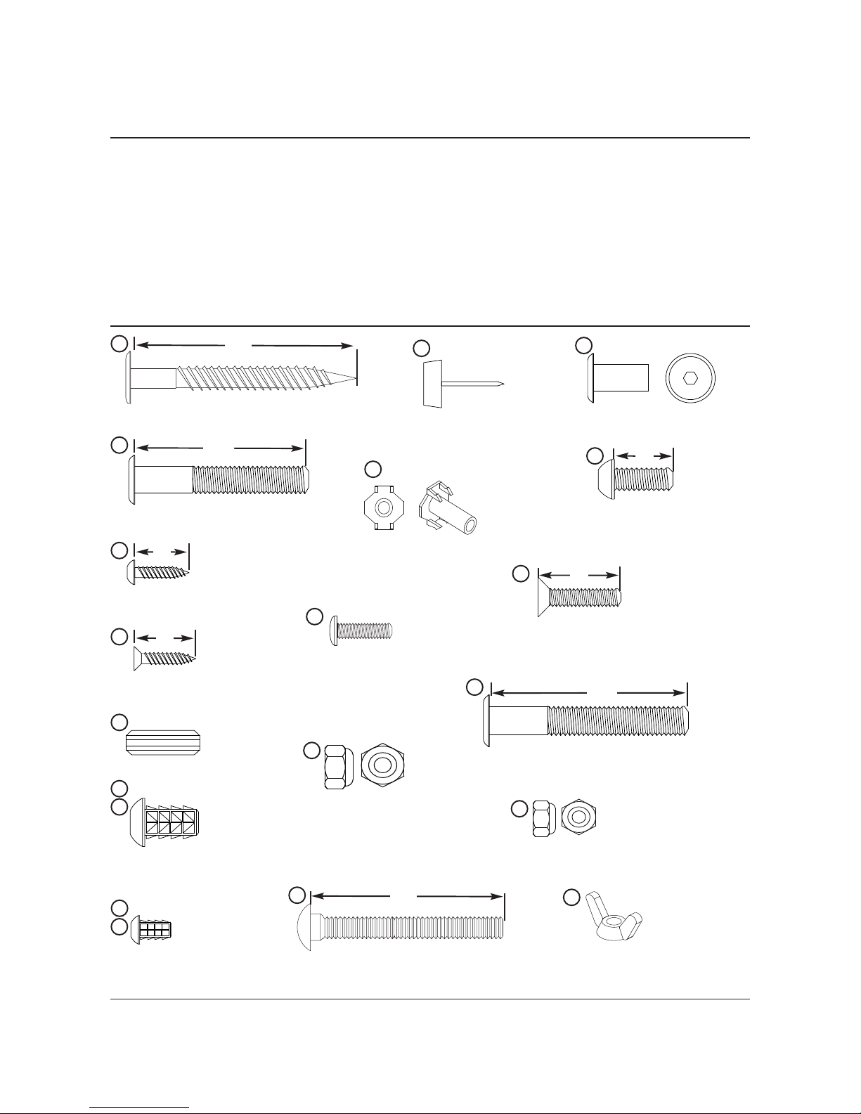
FASTENER PARTS LIST
Screw Insert, 1/4-20x5/8”
Hex Socket Machine Screw
1.57”
3
Wood Dowel
6
9
Hex Socket Lag Screw
2”
2
Hex Cap Insert Nut
41
49
3
/4”
Flat Head Screw (Painted)
Hex Socket Machine Screw
1.77”
56
67
Carriage Bolt
Nylock Nut - 1/4”
Round Head Screw
#10-24x
3
/4”
Crimp Lock Tee Nut (assembled)
Pan Head Screw
5
/8”
4
Flat Head Screw (Painted)
5
/8”
5
11
Screw Insert, 8-32x7/16”
(Oyster or colored)
10
Tack Glide
13
24
26
31
21/2”
32
Hex Socket Button Head Screw
5
/8”
46
Nylock Nut - #10
8
Wing Nut, 1/4”
68
Page 5
5
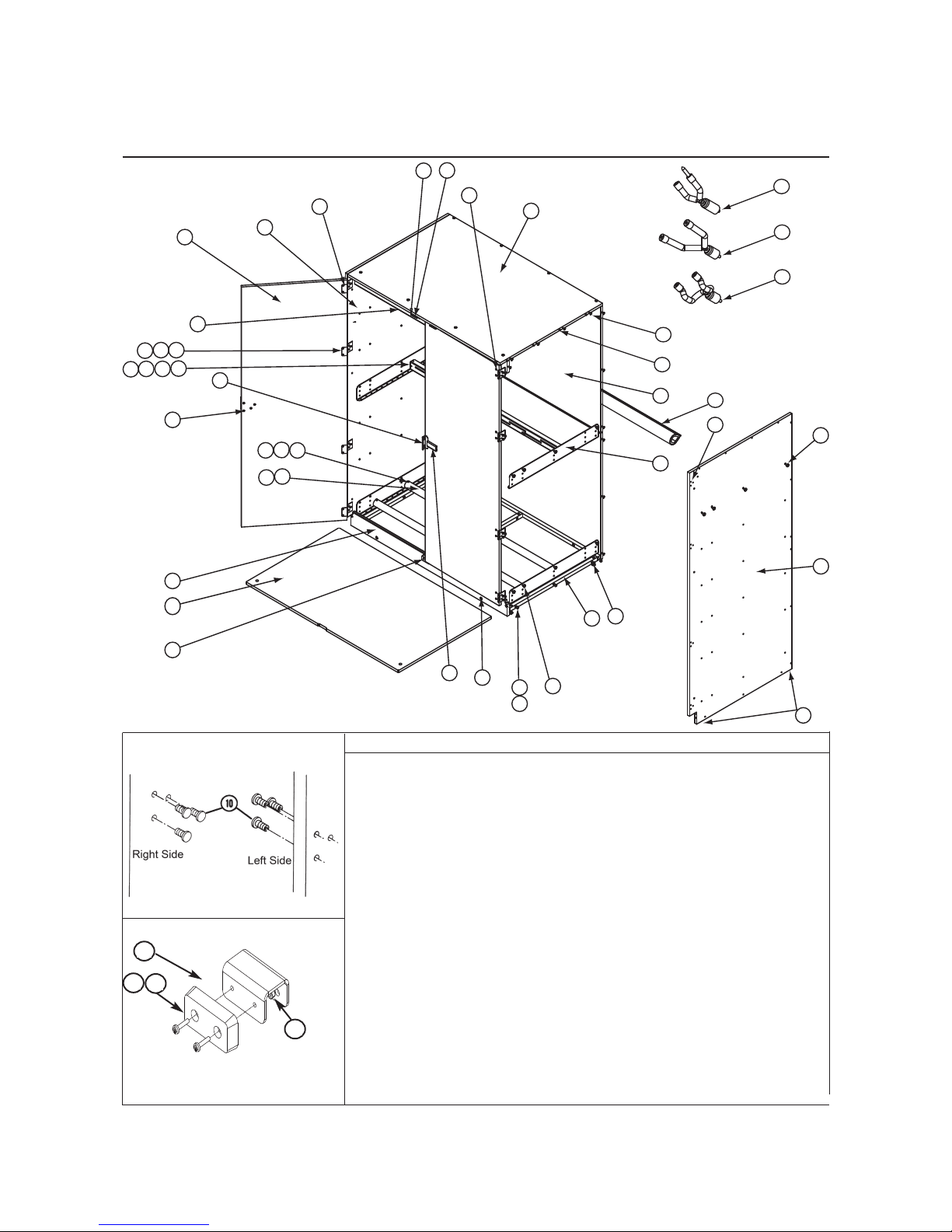
ASSEMBLY
23
49
48
37
33
11
20
13
24
55
68
15
29
50
49
28
46
53
41
34
68
51
32
35
6
21
22
2
4346
4
5
7
58
59
5
25
45
3
9
8
10
25
31
31
Item Description
2 screw, hex-socket lag
3 screw, hex-socket, 40 mm (oyster)
4 screw, pan-head, 5/8"
5 screw, flat-head, 5/8"
6 dowel, wood
8 insert, screw, 1/4"-20 (coordinated color)
9 insert, screw, 1/4"-20 (oyster)
10 insert, screw, 8-32 (oyster)
11 insert, screw, 8-32 (coordinated color)
13 glide, tack
14 screw, painted pan-head, 11/4"
15 rubber bumper
20 panel, top
21 panel, back
22 panel, right-hand side
23 panel, left-hand side
24 crimp-lock tee nut (installed)
25 support tube pad
26 screw, round-head, #10-24
28 instrument support tube
29 floor, cabinet
31 nylon insert lock-nut
Item Description
32 carriage bolt, 1/4"-20x 2.5
33 door
34 handle (wood door only)
35 hinge
37 door catch
41 nut, cap, hex socket
43 upper bar, support
44 trim strip (see page 12)
45 bracket, angle
46 screw, hex-socket button-head
48 panel, top front stretcher
49 screw, painted flat-head, 3/4"
50 panel, bottom front stretcher
51 leveler
53 card holder
55 frame assembly
57 violin / viola / vihuela yoke
58 bass / cello yoke
59 guitar / guitarron yoke
67 nylock nut - #10
68 wing nut, 1/4"
Detail A
Inserts for hinge screws
Screw insert color is oyster.
Detail B
Rubber
Bumper
67
15
9
26
Page 6

6
ASSEMBLY (CONTINUED)
NOTE: Tighten screws snugly, but do not over tighten (use special care with a power screwdriver).
NOTE: Where colored hardware is called out, use the color coordinated to the laminate.
PREASSEMBLE MISCELLANEOUS PARTS
NOTE: The side panels have a notch in the bottom front corner.
1. If Two Full-Length Cabinet Doors will be installed:
Side Panels - (#22 and #23)
a. Lay the side panels (#22 and 23) flat, with their outside
surface up. Note: The outside surface has the largest
part of the crimp lock nut showing.
b. See Detail A. Use a plastic mallet to pound 8-32 screw inserts (#10 oyster) into the twelve holes (four sets of
three holes) located approximately 19/
3
2
" and 1 3/8" from the front edge of both panels. The inserts will be used
later for hinge screws. Refer to pages 10-11
c. Insert 1/4" screw inserts (#9) into the larger holes along the bottom notched edge of both panels.
Front Bottom Stretcher (#50)
a. Lay the front bottom stretcher (#50) flat, with the recessed holes side up.
b. Insert 1/4" screw inserts (#8 coordinated color) into the four larger holes. Note: Two of the holes are recessed.
Back Panel (#21)
a. Insert 1/4" screw inserts (#9) into the three larger holes along the top edge of one of the back panels.
NOTE: The panels are large and hard to keep aligned when you attach them together with screws. Because of this, in
several of the following steps you will be told to “peg” the parts first by inserting wood dowels (#6). These
dowels fit snugly into existing
5
/16"-diameter holes in the panels, and may have to be tapped into place.
2. Insert wood dowels into the side edges of the top panel (#20), the top edge of the top front stretcher panel (#48), and
in the notched out area of the side panels (#22 and 23).
ASSEMBLE THE MAIN PANELS
3. Turn the side panels on edge, with their front edges down. Using the wood dowels, peg the side panels to the top
panel. Then attach the side panels to the side edges of the top panel and the ends of the top front stretcher panel with
2"hex-socket screws (#2 oyster). Tighten the screws using the allen wrench or bit packed with these instructions.
4. With the screw inserts to the inside and edge banding to the middle of the cabinet, peg the two back panels (#21)
together. Attach the back panels to the side and top panels, using the 2" hex-socket screws (#2 oyster).
5. Insert
1
/4" screw inserts (#9) into the three larger holes along the bottom back panel. Attach the back panel using hex
socket machine screw (#3).
6. Attach the frame assembly (#55) to the inside of the side and rear panels with the weldnuts facing down towards the
bottom of cabinet, using 40 mm hex-socket screws (#3 oyster) inside the cabinet and
1
/4" screw inserts (#9 oyster)
outside. Do not tighten the screws.
ATTACH THE GLIDES AND LEVELERS
7. To protect corners and edges while moving the cabinet into place, push or hammer plastic tack glides (#13, not shown)
into the bottom edge of the side panels, about 2" from the corners.
8. Screw the four short levelers (#51) into the frame assembly.
NOTE: If the floor is excessively uneven longer levelers have been included and may be substituted as needed. Full
thread engagement is required on all levelers when installed.
SET THE CABINET UPRIGHT
9. Set the assembled cabinet upright.
10. Attach the bottom front stretcher (#50) to the side panel using the hex-socket screws (#2), hex-socket screw, then use
the 40 mm (#3) and screw insert (#9) to attach the side panel.
11. See Detail B. Attached the rubber bumper (#15) to the bottom front stretcher (#50).
12. Tighten all screws in the cabinet.
INSTALL THE SUPPORT GROUP
13. Refer to operation instructions on pages 7-8.
LEVEL THE CABINET AND MAKE FINAL ADJUSTMENTS
14. Move the cabinet to its intended location, and level it by using a 1/4" socket or screwdriver before putting the floor in
the cabinet. Refer to the leveling procedure on page 9. Insert the floor with the cutout forward.
15. To attach doors, refer to pages 10-11. To attach two or more cabinets together, and to secure the cabinet(s) to the
back wall, refer to pages 12-13.
16. If the cabinet is to be free-standing, it is advisable to use suitable floor-anchoring fasteners to hold the side panels
stationary. Be sure that the cabinet is square and plumb before anchoring.
Page 7
7
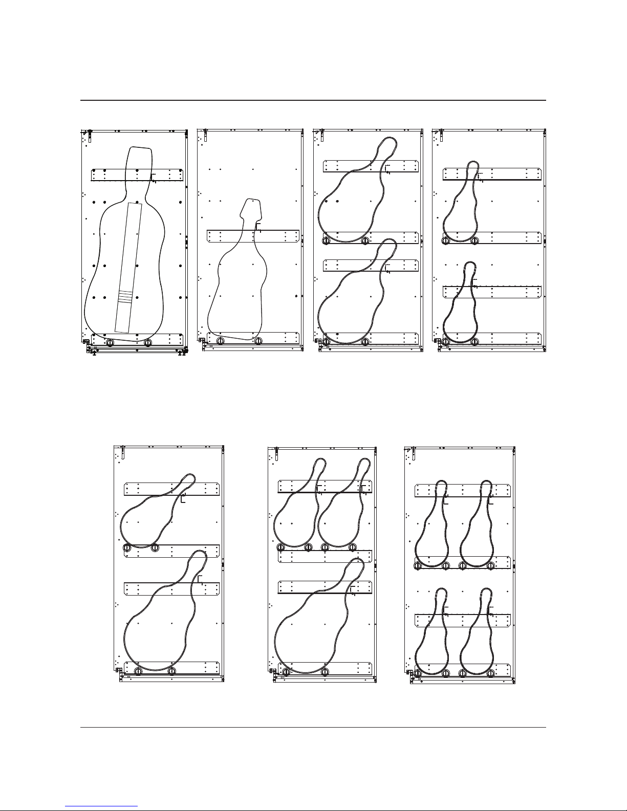
OPERATION
SUPPORT GROUP ARRANGEMENTS
Bass
Cello / Guitarron
Guitar Violin / Viola / Vihuela
Combination - Cello / Guitarron
& Violin / Viola / Vihuela
Cello / Guitarron &
Violin / Viola / Vihuela
Violin / Viola / Vihuela
Combination
High- Pack
Options
Page 8

8
OPERATION (CONTINUED)
The basic support group consists of 4 side brackets, 2 padded instrument support tubes and 1 upper
support bar. From the sketches above and on page 7, select the approximate arrangement desired.
1. Place 2 side brackets onto the cabinet side panels at the same level and with the same orientation
(flange up or down) to receive the instrument support tubes. Note: Four 1/4”-20 x 5/8” button head
fasteners (#46) are required per side bracket.
2. Install the support tube pad onto the instrument support tube with the seam of the pad on the flat
edge of the tube.
3. Loosely lay one instrument support tube on the brackets in the desired position and insert the
required hardware (#31 and 32) to determine if there is adequate clearance to continue assembly.
4. To get an approximate instrument support tube to instrument support tube spacing, place them side
by side on the floor. Using a common instrument case or instrument securely held, move the
instrument support tubes apart or together until they fit and support the bottom of the instrument
case or instrument reclined at the desired angle.
Note: This is the dimension to the nearest hole location on the side bracket. It should be used to
locate the instrument support tubes with respect to each other onto the side brackets.
5. Place the instrument support tubes, with the flat side and support tube pad seam down, in the
desired location(s), confirm they are evenly spaced and parallel to the back of the cabinet. Then
tighten all bracket and support tube fasteners.
6. Place a common instrument case or instrument and lean it back at the desired angle. Note where
the upper support bar would be best positioned to contact the neck of the instrument and hold it
securely.
7. Install the side brackets onto the cabinet side panels using
1
/4”-20 x 5/8” button head fasteners (#46)
at the same level and with the same orientation to receive the upper support bar.
8. Install the upper support bar using 1/4”-20 x 5/8” button head fasteners (#46) and lock-nut (#31). Wing
nut (#68) may be used in place of the nylock nut (#31) if frequent adjustment is required. Nylock
nuts (#31) are recommended for a more secure upper support bar mounting. Tighten all fasteners
securely.
Note: The upper support rail can be mounted above or below the flange for increased versatility
instrument cases or instruments should not be installed so upright that they would tip off the support
rails. A reclining angle of 30 to 45 degrees is recommended. Instrument cases or instruments
should be placed on the support tubes and rails to be parallel with the side panels of the cabinet so
the instrument case or instrument does not fall to one side or the other
It is highly recommended that instruments stored in the cabinet, without cases, use neck supports
for best security. The neck supports are available in 3 different sizes based on the type of
instrument and mount onto the upper support rail. The upper support rail can be located up and
down or near and far. The individual neck supports can be located side to side. Two flat washers
are provided and are to be placed in front and in back of the upper support bar slot on the
1
/4”-20
threaded rod of the neck support. This allows the washers to clamp and hold the neck support on
the upper support bar.
9 Insert and remove all instruments carefully to avoid damage and avoid knocking over other
instruments.
SUPPORT GROUP ARRANGEMENTS INSTRUCTION:
Page 9

9
1. Check the level of the
entire floor where the
cabinets will be
installed. Determine
the highest point of
the floor in that area.
Extend all levelers
until the bottom of the
cabinet will be higher
than the highest point
in the floor.
2. Adjust the levelers on
one side until the front
edges of the cabinet
side panels are plumb
(side-to-side).
3. Measure A and B with a tape
and adjust the front levelers
until A=B (+1/32inch).
4. Adjust both front levelers
equally until the front
edges of the cabinet are
plumb (front-to-back).
5. Recheck that A=B.
Readjust if necessary
(repeat steps 2-4).
6. Adjust the levelers on the next cabinet so it
will line up with the top of the first cabinet.
7. Repeat steps 2-5 for the second cabinet.
8. Continue in the same manner until all cabinets
are leveled.
TO LEVEL CABINETS
NOTE: Do not try to level the cabinets to match soffits.
Do not try to plumb the cabinet to match adjacent walls.
For proper door alignment, follow these instructions carefully.
Page 10

10
NOTE: The cabinet must be properly leveled first, or the doors will not fit properly. See page 9
1. Lay the door (#33) flat. Use a plastic mallet to pound 8-32 screw inserts (#11) into the eight holes (four pairs)
near one edge of each door (install inserts into the front
face of the door). Note: There are pilot holes started
on the front face of the door.
2. Attach four hinges (#35) to the inside (back face) of each door, using flat-head 3/4" screws
(#49 matches hinge color) into the inserts installed in step 1.
3. See Detail G. Hold a door in position on the cabinet. Attach the hinges to the side panel,
using three flat-head screws (#49 matches hinge color) into each set of screw inserts.
A screw may be inserted into the rear-most hole of the cabinet and the door may be hung from it by placing the
slotted hole in the hinge onto the screw and moving the hinge forward until the other two screw inserts are
exposed. Tighten the three screws in each hinge. Repeat with the other door.
Four sets of screw inserts (#10 oyster) were previously installed in the left and right side panels for the door
hinges. See Detail A on the cabinet assembly instructions.
4. Secure each hinge to the edge of the door, using flat-head
5
/8" screws (#5 matches hinge color) into the
predrilled hole.
5. See Detail H. Insert a card holder housing (#70) into the two inner holes in the front face of the left
door as
shown. Insert the other card holder housing to the inner holes in the right
door. Insert hex-socket cap nuts (#41
matches hinge color) into the holes in the back face of the door and tighten them.
6. Insert the handle (#34 matches hinge color) into the remaining two holes in each door. Install and tighten the
cap nuts.
Closing the doors align holes in the handles for installing a padlock.
7. See Detail L. Attach the door catches (#37) to the holes in the underside of the top panel, where the
doors meet, using
5
/8" pan-head screws (#4) into the predrilled holes.
TO ATTACH FULL-LENGTH WOOD DOORS
Detail G
Left side hinge installation
To identify the front
and back faces of
the door, see also
Detail G on page 50
Detail H
Card Holder & Handle Installation
Detail L
Door catch installation
Item Description
4 screw, pan-head, 5/8"
5 screw, painted flat-head, 5/8" (matches hinge color)
10 insert, screw, 8-32 (oyster)
11 insert, screw, 8-32
33 door
34 handle (matches hinge color)
35 hinge
37 catch, door
41 nut, cap, hex-socket (matches hinge color)
49 screw, painted flat-head,
3
/4" (matches hinge color)
53 holder, card
70 housing, card holder
Page 11

11
NOTE: The cabinet must be properly leveled first, or the doors will not fit properly. See page 9.
1. Four sets of screw inserts (#10 oyster) were previously installed in the left and right side panels
for the door hinges. See Detail A on the cabinet assembly instructions.
2. See Detail G. Four hinges are welded to full-length grille doors at the factory. Hold a door (#33) in
position on the cabinet. Attach the hinges to the side panel, using three pan-head screws (#8) into
each set of screw inserts. A screw may be inserted into the rear-most hole of the cabinet and the door
may be hung from it by placing the slotted hole in the hinge onto the screw and moving the hinge
forward until the other two screw inserts are exposed. Tighten the three screws in each hinge.
Repeat with the other door.
3. Closing the doors will align holes in the two lock housing for installing a padlock.
4. See Detail L. Attach the door catches (#37) to the holes in the underside of the top panel, where the
doors meet, using 5/8" pan-head screws (#4) into the predrilled holes.
TO ATTACH FULL-LENGTH GRILLE DOORS
Detail G
Left side hinge installation
Detail L
Door catch installation
Item Description
4 screw, pan-head, 5/8"
10 insert, screw, 8-32 (oyster)
33 door
37 catch, door
49 screw, painted flat-head,
3
/4"
(matches hinge color)
Page 12

NOTE: The following instructions are for standard installations.
- For seismic installation instructions, see 145R422.
- For AcoustiCabinet refer to pages 14-21.
TO SECURE CABINETS TOGETHER
NOTE: Make sure the cabinets are in position and level before you secure them together.
1. See Detail M. Install two trim strips (I-shaped plastic strips) (#44) on the side panel of one of the two
mating cabinets. Install the longer strip
1
/8" back from the front edge and install the shorter strip
at the bottom 2
3
/4" back from the front edge.
The top of the longer strip should be flush with the top of the cabinet.
The end of the strip, with the hole, goes to the top.
To attach, peel the paper from the pressure-adhesive tape and press the strip into place.
This will hold the strips in position until the cabinets are bolted together in step 2.
2. There are three holes predrilled in the side panels for securing the cabinets together.
These holes are located
1
13
/16" back from the front edge of the cabinet, and 6", 33 1/2", and 75" down from the top.
With a plastic mallet, pound three
1
/4-20 screw inserts (#9 oyster) from one side of each hole,
Install 1.77" (45 mm) hex-socket screws (#56) through the other side, and tighten.
TO SECURE CABINETS
12
Securing cabinets together
Detail M
Installing
trim strips
Item Description
9 insert, screw, 1/4-20 (oyster)
44 trim strip
56 screw, hex-socket, 45 mm
Cabinets are unsafe unless
secured as specified.
!
WARNING
Use methods appropriate to
your wall surfaces.
!
WARNING
Front of Cabinets
Top View
1/8”
2-3/4”
Shorter
Trim Strip
Longer
Trim Strip
Page 13

13
NOTE: The following instructions are for standard installations. For seismic installation instructions,
see 145R422.
TO SECURE CABINETS TO THE BACK WALL
There are L-shaped brackets (#45) in the hardware bag for attaching the cabinets to your wall surface.
Because of the variety of possible wall surfaces, fasteners are not included. Have your maintenance
people recommend an appropriate type for safe, secure attachment.
NOTE: Make sure all the cabinets are secured together before you attach them to the back wall.
1. See Detail N. Using the L-shaped brackets, you can tie cabinets together and to the wall surface at
the top. The brackets have extra holes: if the cabinets can’t be positioned tight against the wall, you
can slide the bracket back as much as 2" until it is tight against the wall surface.
2. Use the necessary fasteners suggested by your maintenance people to secure the cabinets to the
wall. At least every 5th cabinet must be attached to the back wall surface.
TO SECURE CABINETS (CONTINUED)
Detail N
Installing wall brackets
Item Description
4 screw, pan-socket, 5/8”
45 bracket, L-shaped
Page 14

14
TO SECURE CABINETS (CONTINUED)
TO SECURE CABINETS BACK TO BACK
If cabinets are installed back-to-back in a “island” or “peninsula” formation, you must drill holes through
the back of each cabinet and secure the backs of the cabinets together.
NOTE: Make sure the cabinets are in position and level before you secure them together.
1. Using a 3/8" drill, make holes 2 5/8" down from the top (inside) on the back of the cabinets that are
back-to-back. These holes should be no closer than 4" from the side of the cabinet. Drill through the
back of the opposite cabinet. You may also need to make holes 2 1/2" up from the bottom of the cabinets.
2. With a plastic mallet, pound 1/4-20 screw inserts (#9 oyster) from the inside of one of the cabinets.
Have someone inside the opposite cabinet install 1.77" hex-socket screws (#56) and tighten.
Item Description
9 insert, screw, 1/4-20
(oyster)
56 screw, hex-socket, 50 mm
Connecting Holes
(sides of cabinets — see page 9)
Connecting Holes
(backs of cabinets)
Page 15

15
ACOUSTICABINET BACKING ATTACHMENT
Detail O
Flip-Stix
®
To attach the sound absorptive material to the back of the AcoustiCabinets:
1. See Detail 0. Flip-Stix®(#80) are used to hold the sound absorptive material in place.
The Flip-Stix®are already attached to the rear stretcher panels on the back of all AcoustiCabinets
to attach the sound absorptive material. The quantity of Flip-Stix®installed on the cabinet will vary
by cabinet design.
On each Flip-Stix®, pull the top tab out approximately 11/2”.
2. See Detail P. Attach the sound absorptive material (#81) to the back of the cabinet by placing it
over all of the Flip-Stix®approximately 2” above the desired final location with the white (printed)
plastic barrier facing away from the cabinet back.
3. Pull down on the sound absorptive material to secure it into place on the Flip-Stix®and pulling it level.
The Flip-Stix® are intended to penetrate the gray plastic and the insulation only, not the white
(printed) plastic barrier.
Item Description
80 Flip-Stix
®
81 sound absorptive material
Detail P
Attach sound absorptive material
Note: AcoustiCabinets shown on the next few pages are for
illustration purposes only. They do not reflect the exact
cabinet dimensions.
Holes in Upper Panel
21
21
Holes in Lower Panel
80
80
6
1½”
81
81
Page 16

16
TO SECURE CABINETS TOGETHER
NOTE: Make sure the cabinets are in position and level before you secure them together.
1. See Detail Q. Install two trim strips (I-shaped plastic strips) (#44) on the side panel of
one of the two mating cabinets.
Install the longer strip 1/8" back from the front edge and install the shorter strip at the bottom 2 3/4"
back from the front edge.
The top of the longer strip should be flush with the top of the cabinet.
The end of the strip that has a hole goes to the top.
To attach, peel the paper from the pressure-adhesive tape and press the strip into place.
This will hold the strips in position until the cabinets are bolted together in step 2.
2. a. See Detail R. For flush back mounting (recommended): There are three holes predrilled in
the side panels for securing the cabinets together. These holes are located 113/16" back from
the front edge of the cabinet, and 6", 33 1/2", and 75" down from the top.
b. For flush front mounting: Align the cabinets to be flush in the front.
Use the three predrilled holes in the shallowest cabinet as the template for the remaining
cabinet. Using the 3/8” drill bit, drill new holes into the side panel of the adjacent cabinet.
3. With a plastic mallet, pound three 1/4-20 screw inserts (#9 oyster) from one side of each hole,
Install 1.77" (45 mm) hex-socket screws (#56) through the other side, and tighten.
TO SECURE THE ACOUSTICABINET
Detail R
Securing cabinets together
Detail Q
Installing
trim strips
Item Description
9 insert, screw, 1/4-20 (oyster)
44 trim strip
56 screw, hex-socket, 45 mm
Cabinets are unsafe unless
secured as specified.
!
WARNING
Use methods appropriate to
your wall surfaces.
!
WARNING
Front of Cabinets
Top View
1/8”
2-3/4”
Shorter
Trim Strip
Longer
Trim Strip
Page 17

17
TO SECURE THE ACOUSTICABINET (CONTINUED)
TO INSTALL COVER PANELS
1. See Detail S. Insert two plastic guide tacks (#84) into the bottom of each cover Panel (#85),
centered and 2-3” from each end.
2. See Detail T. Lift the cover panel to a vertical position and fit it into place over the exposed
hardware. Use the plastic guide tacks to protect the bottom of the cover panel.
The cover panel should fit flush against the front side of the cabinet and overhang the back side by
2
1
/2”. If it does not, check to see if it is a left hand cover panel on the left side of the cabinet (or right
hand on the right side).
3. Lay the cover panel back down onto the packaging.
84
85
84
Detail T
Securing cabinets together
Detail S
Installing guide tacks
Item Description
84 guide tack
85 cover panel
NOTE: Cabinet side is not
shown for clarity.
Page 18

TO INSTALL COVER PANELS (C
ONTINUED
)
4. See Detail U. Using the 3/
1
6
” drill bit, drill 12 holes (9 holes for 68” tall cabinets) into the side panel of
the cabinet to be covered:
Top Row
NOTE: Do not drill into a shelf or cross member. Measure before drilling so that the hole is
1-2” from the nearest horizontal surface to allow clearance for tools.
a. Drill a hole 2-3” down from the top and 2-3” back from the front of the cabinet.
b. Drill the second hole 2-3” down from the top and 24-26” (14-16” for 191/4” deep cabinets)
from the front of the cabinet.
c. Drill a third hole 2-3” down from the top and evenly spaced horizontally between the first
two holes.
Bottom Row
NOTE: Do not drill into a shelf or cross member.
Measure before drilling so that the hole
is 1-2” from the nearest horizontal
surface to allow clearance for tools.
d. Drill a hole 7-8” up from the bottom
and 2-3” back from the front of the
cabinet.
e. Drill the second hole 7-8” up from
the bottom and 24-26” (14-16” for
19
1
/4” deep cabinets) from the front
of the cabinet.
f. Drill a third hole 7-8” up from the
bottom and evenly spaced
horizontally between the first
two holes.
Middle Rows
NOTE: Do not drill into a shelf or
cross member. Measure before
drilling so that the hole is 1-2” from
the nearest horizontal surface to
allow clearance for tools.
g. Drill two rows (1 row for 68” tall
cabinets) evenly spaced
between the top and bottom rows.
Use the same vertical spacing as
the top and bottom rows.
18
TO SECURE THE ACOUSTICABINET (CONTINUED)
Detail U
Drill holes in
side panel
Page 19

TO INSTALL COVER PANELS (CONTINUED)
5. See Detail V. Place the cover panel into position covering the cabinet side panel and flush
with the front edge as in Step 2.
6. Clamp securely in position using at least two non-marring padded clamps.
7. Insert all twelve of the wood screws (#82).
Do not over-torque or strip out the screws. Tighten securely and remove the clamps.
19
TO SECURE THE ACOUSTICABINET (CONTINUED)
Detail V
Install cover panel
NOTE: Cabinet side is not
shown for clarity.
Page 20

20
NOTE: The following instructions are for standard installations. For seismic installation instructions,
contact the Wenger Corporation.
TO SECURE CABINETS TO THE WALL
There are three methods for attaching AcoustiCabinets to a wall surface:
• 21/2” from wall (recommended)
• Greater than 21/2” from wall
• Flush with the wall.
CABINETS 21/2” FROM WALL (RECOMMENDED)
There are wall brackets (#45) for attaching the cabinets to your wall surface. Because of the variety
of possible wall surfaces, fasteners are not included. Have your maintenance people recommend an
appropriate type for safe, secure attachment.
NOTE: Make sure all the cabinets are secured together before you attach them to the wall.
1. See Detail W. Attach the wider tabbed surface of the mounting bracket to the top edge
at the back of the cabinet using four 5/8” pan head screws (#68) in the front four holes.
The tabs should be flush with the cabinet and all open areas at the top of the cabinet should be
covered by the mounting bracket (see the following page for cabinets that are a different size
than the mounting bracket).
2. Position the cabinets with the mounting brackets against the wall. Using the wall brackets,
attach the cabinets to the wall surface.
The brackets allow the recommended 21/2” spacing between the cabinet and the wall surface.
3. Use the necessary fasteners suggested by your maintenance people to secure the cabinets to the
wall. Every AcoustiCabinet must be attached to the back wall surface.
TO SECURE THE ACOUSTICABINET (CONTINUED)
2½”
Cabinet Top
Back Wall
4
Tab
82
Detail W
Installing
wall brackets
Item Description
4 screw, pan-socket, 5/8”
82 bracket, wall
Page 21

21
DIFFERENT SIZE CABINETS
1. See Detail X. Flatten the tab on the mounting bracket at the side that will be closest to and overlap
the wider cabinet or trim the mounting bracket to fit if preferred.
2. Overlap the mounting bracket from the narrower cabinet with the mounting bracket for the wider
cabinet.
Full width cabinets should always be on the on the outside run of cabinets.
3. See Detail Y on previous page. Attach the wider tabbed surface of the mounting brackets to the
top edge at the back of the cabinets using 5/8” pan head screws (#68).
The tabs should be flush with the cabinet and all open areas at the top of the cabinet should be
covered by the mounting bracket.
4. Position the cabinets with the mounting brackets against the wall. Using the wall brackets,
attach the cabinets to the wall surface.
The brackets allow the recommended 21/2” spacing between the cabinet and the wall surface.
5. Use the necessary fasteners suggested by your maintenance people to secure the cabinets to the
wall. Every AcoustiCabinet must be attached to the back wall surface.
TO SECURE THE ACOUSTICABINET (CONTINUED)
60”
Cabinet
Flatten Tab
Overlap
Mounting Bracket
Detail X
Page 22

22
TO SECURE THE ACOUSTICABINET (CONTINUED)
CABINETS GREATER THAN 21/2” FROM WALL
1. See Detail W. Flatten the tabs on the mounting bracket.
2. Attach the mounting bracket to the back of the cabinet, over the sound absorptive material.
3. Mount a stud to the wall using the necessary fasteners suggested by your maintenance people.
4. Attach the closure panel to the top of the mounting bracket and wall stud.
3. Refer to the “Cabinet Closure Kits Assembly Instructions” that accompanies the optional
closure panels for more detailed instructions.
Wall
Closure
Panel
Mounting
Bracket
Sound Absorbtive M at er ial
Wall
Stud
Detail Y
Installing closure panels
Page 23

23
CABINETS FLUSH WITH WALL (NOT RECOMMENDED)
1. See Detail Z. Flatten the tabs on the wider tabbed surface of the mounting bracket.
2. Position the mounting bracket to extend between 1/4” to 21/2” beyond the back of the cabinet.
Overlap mounting brackets for different size cabinets as indicated under “Different Size Cabinets”
on the previous page.
3. Attach the mounting bracket to the top edge at the back of the cabinet using four 5/8” pan head
screws (#68) in the front four holes.
4. Trim the end cover panels to extend between 1/4” and 21/2” beyond the back of the cabinets.
5. Position the cabinets against the wall. Using the wall brackets, attach the cabinets to the wall
surface.
6. Use the necessary fasteners suggested by your maintenance people to secure the cabinets to
the wall. Every AcoustiCabinet must be attached to the back wall surface.
TO SECURE THE ACOUSTICABINET (CONTINUED)
Cabinet Top
Back Wall
4
Flatten
tab
82
¼” min
Detail Z
Installing
flush to
wall
Item Description
4 screw, pan-socket, 5/8”
82 bracket, wall
Page 24

24
CLEANING
For removal of mild stains and mild scuff marks, the polyester wood panels and polyester shelves may
be cleaned using an all-purpose household cleaner (409, Fantastic, or similar), or just simple mild soap
and water.
For heavier scuff marks, ink stains, felt pen and magic marker stains, or other tough stains; use a nonabrasive cleaner (Soft Scrub or similar), or an industrial all-purpose cleaner (Acetone or similar).
Ammoniated or vinegar-based glass cleaners also work well for these stains.
Do not use harsh abrasive cleaners, as permanent damage could occur to the panel surface. Be sure to
quickly remove all cleanser residues with water and wipe dry with a soft cloth.
HUMIDITY CONTROL
To insure longevity of panel performance, maintain the relative humidity between 25% - 55% at the
permanent installation site.
STORAGE CABINET MAINTENANCE
 Loading...