

Page 1
Assembly/Operating Instructions
StageTek™Guardrail
Basic Instructions only!
For Replacement Parts and more detailed product information,
refer to the StageTek
™
Owner’s Manual 280A099.
!
CAUTION
Make sure anyone assembling
or installing the StageTek
component has read and
understands the instructions.
!
CAUTION
Always comply with Warnings
or Cautions in the instructions
or posted on the equipment.
Guardrails are recommended
for instances where the deck
height is 12” (30 cm) or more.
!
CAUTION
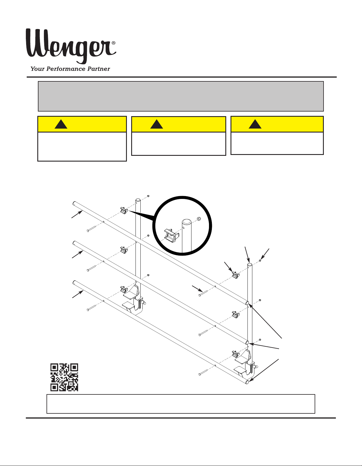
ASSEMBLY WITHOUT OPTIONAL INFILL PANELS
To assemble the Guardrail without the optional Infill Panels, attach Rails to the top, middle and
bottom positions of both Upright Weldments using 3/8-16 x 3-3/4” Carriage Bolts, Tube Saddles
and 3/8-16 Acorn Nuts as shown.
Tube Saddle
Orientation
Top
Rail
3/8-16
Acorn
Nut
Middle
Rail
Upright
Weldment
Tube
Saddle
3/8-16 x 3-3/4”
Carriage Bolt
Bottom
Rail
End Caps
may need to
be installed
in Rail Ends
Visit the StageTek web page at www.wengercorp.com
for detailed instructions and videos.
Note: Please read and understand the instructions before starting the assembly or installation.
Note: If you need additional information, contact Wenger Corporation using the information below.
©Wenger Corporation 2013 Printed in USA 04/13 Part #281A442-03
Wenger Corporation, 555 Park Drive, P.O. Box 448, Owatonna, Minnesota 55060-0448
Questions? Call.....USA: 800-4WENGER (493-6437) • Worldwide: 1-507-455-4100 • www.wengercorp.com
Page 2
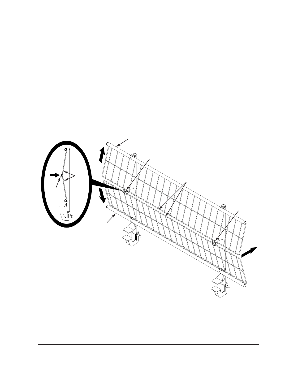
ASSEMBLY WITH OPTIONAL INFILL PANELS
To assemble the Guardrail with the Optional Infill Panels:
1. Attach a Rail to both the top and bottom positions of both Upright Weldments using
3/8-16 x 3-3/4” Carriage Bolts, Tube Saddles and 3/8-16 Acorn Nuts as described on
the previous page.
Do not attach the Middle Rail yet.
2. With the vertical wires facing outward, center an Infill Panel to fit into the channel of both attached
Tube Saddles behind both the Top and Bottom Rails.
3. Place a Tube Saddle between the Top and Bottom Infill Panels at both ends to align with the
pre-drilled middle hole in the Upright Weldments.
4. Push the Tube Saddles and Infill Panels inward to be flush with the Upright Weldments.
Top
Rail
Tube
Saddle
Tube
Saddle
Infill
Panels
(Vertical Wires Facing Out)
Infill Panels
Tube
Saddle
Bottom
Rail
2
Page 3

ASSEMBLY WITH OPTIONAL INFILL PANELS (CONTINUED)
5. Attach the Middle Rail to both
Upright Weldments using
Tube
Saddle
a 3/8-16 x 3-3/4” Carriage Bolt
through the Tube Saddle
and an 3/8-16 Acorn Nut as
previously described.
Middle
Rail
3/8-16 x 3-3/4”
Carriage Bolt
6. Secure the Top and Bottom Infill Panels to the Rails using
evenly distributed Spacers and Nylon Ties as shown.
3/8-16
Acorn Nut
a. Orient the Nylon Tie
with the head towards
the bottom of the assembly.
b. After the Nylon Tie has
been tightened, trim off
any excess to be flush
with the head.
Head of
Nylon Tie
Head Towards
Botttom
and Trim Off
Excess
Nylon
Tie
Spacer
3
Page 4

OPERATION
To attach the Guardrail to the stage deck:
1. Be sure that the Lower Slide at the base of both Upright Weldments
are in the Open Position.
To move the Lower Slide to the Open Position:
a. Loosen the Knob.
b. Rotate the Pivot Lock back from the Lower Slide.
c. Move the Lower Slide down to the Open Position.
2. Using two people, lift the Guardrail Assembly to rest on the stage deck as shown.
The Lower Slides should fit under the edge of the stage deck and be tight against the
bottom of the stage deck when in the closed position.
!
CAUTION
Two people are required to lift the
Guardrail Assembly onto the stage deck.
3. Move the Lower Slides to the Closed Position:
a. Move the Lower Slide up to the Closed Position.
b. Rotate the Pivot Lock over the Lower Slide.
c. Tighten the Knob.
Lower Slide
Closed Position
Lower Slide
Open Position
Knob
4” (10 cm)
Maximum Gap
Pivot
Lock
!
WARNING
The Guardrail Assembly is not secure
until it is locked into the Closed
Position on the stage deck as specified.
If multiple Guardrail Assemblies with Optional Infill Panels are being attached,
the gap between them can be no more than 4” (10 cm) apart as shown.
4
 Loading...