

Page 1

Owner’s Manual
Trouper™and Stagehand
™
Platform Systems
T
ROUPER PLATFORM
SYSTEMS
Safety Precautions . . . . . . . . . . . . . . . . . . . . . . . . . . . . . . . . . . 3
Warranty . . . . . . . . . . . . . . . . . . . . . . . . . . . . . . . . . . . . . . . . . . 4
Introduction. . . . . . . . . . . . . . . . . . . . . . . . . . . . . . . . . . . . . . . . 5
Unpacking or Setting Up for the First Time . . . . . . . . . . . . . . . 5
Setting Up Individual Platform Units. . . . . . . . . . . . . . . . . . . . . 6
Same-Height Platform Systems
Connecting Same-Height Platforms . . . . . . . . . . . . . . . . . . . . 8
Installing Guard Rails . . . . . . . . . . . . . . . . . . . . . . . . . . . . . . . 9
Installing Drapery Enclosures. . . . . . . . . . . . . . . . . . . . . . . . 10
Installing the Stairway(s). . . . . . . . . . . . . . . . . . . . . . . . . . . . 11
Installing a Backdrop . . . . . . . . . . . . . . . . . . . . . . . . . . . . . . 12
Riser Platform Systems
Typical Riser Layouts . . . . . . . . . . . . . . . . . . . . . . . . . . . . . . 13
Connecting Riser Sections . . . . . . . . . . . . . . . . . . . . . . . . . . 14
Installing Chair Stops . . . . . . . . . . . . . . . . . . . . . . . . . . . . . . 17
Installing Closure Panels . . . . . . . . . . . . . . . . . . . . . . . . . . . 17
Installing Guard Rails . . . . . . . . . . . . . . . . . . . . . . . . . . . . . . 19
Disassembling the Platform System. . . . . . . . . . . . . . . . . . . . 20
Loading the Storage Carts . . . . . . . . . . . . . . . . . . . . . . . . . . . 21
Maintenance . . . . . . . . . . . . . . . . . . . . . . . . . . . . . . . . . . . . . . 22
Replacement Parts List . . . . . . . . . . . . . . . . . . . . . . . . . . . . . 22
Safety Precautions . . . . . . . . . . . . . . . . . . . . . . . . . . . . . . . . . 33
Warranty . . . . . . . . . . . . . . . . . . . . . . . . . . . . . . . . . . . . . . . . . 34
Introduction. . . . . . . . . . . . . . . . . . . . . . . . . . . . . . . . . . . . . . . 35
Unpacking or Setting Up for the First Time . . . . . . . . . . . . . . 35
Setting Up Individual Platform Units. . . . . . . . . . . . . . . . . . . . 36
Connecting Same-Height Platforms . . . . . . . . . . . . . . . . . . . . 37
Installing Guard Rails . . . . . . . . . . . . . . . . . . . . . . . . . . . . . . . 38
Installing Drapery Enclosures. . . . . . . . . . . . . . . . . . . . . . . . . 39
Installing the Stairway(s). . . . . . . . . . . . . . . . . . . . . . . . . . . . . 40
Installing a Backdrop . . . . . . . . . . . . . . . . . . . . . . . . . . . . . . . 41
Disassembling the Platform System. . . . . . . . . . . . . . . . . . . . 42
Transporting and Storing Platform Units. . . . . . . . . . . . . . . . . 43
Maintenance . . . . . . . . . . . . . . . . . . . . . . . . . . . . . . . . . . . . . . 44
Replacement Parts List . . . . . . . . . . . . . . . . . . . . . . . . . . . . . 44
This publication includes complete Owner’s Manuals for both the Trouper and Stagehand Platform
Systems.
Please take a few minutes to read the appropriate sections and to familiarize yourself with Trouper
or Stagehand’s operating features. If you should need additional information, just write or call.
STAGEHAND
PLATFORM
SYSTEMS
©Wenger Corporation 2005 Printed in USA 09/05 Part #176A700-5
Wenger Corporation, 555 Park Drive, P.O. Box 448, Owatonna, Minnesota 55060-0448
Questions? Call.....USA: (800) 733-0393 • International (call collect): (507) 455-4100 • www.wengercorp.com
Page 2

2
Trouper Platform Systems
Page 3
3
SAFETY PRECAUTIONS
SETUP
Insist that anyone who assists with the set up of
the Trouper Platform System be familiar with
this manual.
GUARD RAILS
The guard rails are indicators of the perimeter of
the platform system, and are not intended as a
universal restraint. Excess weight or pressure
will cause them to collapse.
Never use the rails:
• As a crowd barrier
• As a perch
• As a tie-down.
PLATFORM STABILITY
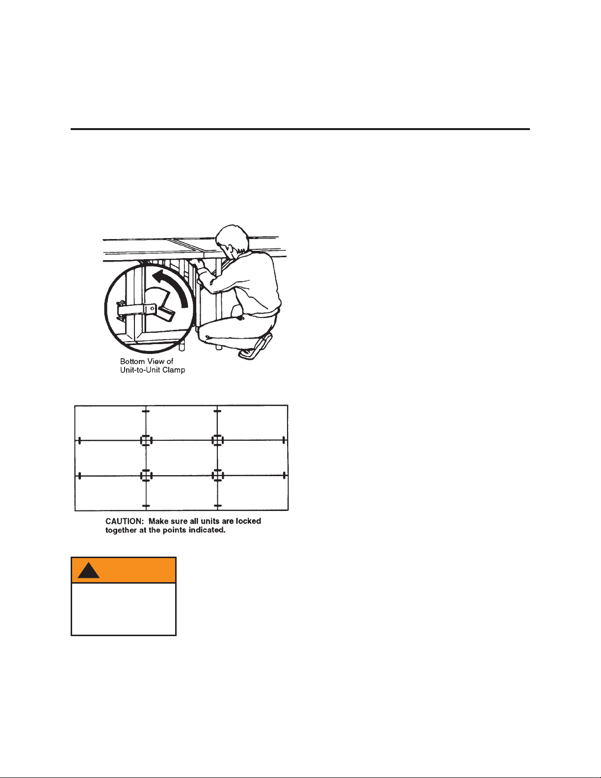
All platform units must be locked together using
the unit-to-unit clamps beneath the stage
surface. These clamps are designed for use
only with one-level stage sets. Do not set up a
multilevel stage using Trouper units unless
adequate special clamping is provided to secure
the levels together. See “Connecting Riser
Sections” on page 14.
Trouper platforms are designed for level
surfaces only and contain no provision for
adjusting leg heights.
TRANSPORT/STORAGE CARTS
Never stack more than three platforms on a
3-Unit Cart, six platforms on an 6-Unit Cart,
eight platforms on an 8-Unit Cart, or twelve
platforms on a 12-Unit Cart.
Before moving or storing platforms on 6- or 8Unit Carts, always secure the units using the
unit lock assembly at the top of the cart. On a
12-Unit Cart, secure the units by slipping them
into the guides on the upright handle assembly.
See “Loading the Storage Carts” on page 21 for
more information.
Throughout this manual, you will find CAUTIONS and WARNINGS:
• WARNING means that if safety information is not followed someone could be seriously
injured or killed.
• CAUTION means that if safety information is not followed the platform could be damaged or
personal injury could result.
!
CAUTION
To avoid injury,
some setup steps
may require two
workers.
!
WARNING
Rails may collapse
if excess weight or
pressure applied.
!
WARNING
Platforms can fall
unless stacked and
secured properly
on the cart.
!
WARNING
Platforms are
unsafe if unit-tounit clamps are not
used as specified.
Page 4

WARRANTY
Wenger Trouper Platform Systems are guaranteed free of defects in
materials and workmanship for five full years.
Our guarantee assures you of either a full refund or repair or
replacement of the defective materials or workmanship without charge,
at the discretion of our Customer Service Department. Just call a
Customer Service Representative at 1-800-733-0393 and state the
reason you are dissatisfied. If a product return is necessary, your
Representative will issue a return authorization. This is your sole remedy
for breach of this warranty.
Should you have a question or problem with any Wenger product, don’t
hesitate to call, even if the product is past warranty. It’s important to us
that all our customers be satisfied.
This is the sole warranty made by Wenger. Wenger disclaims all other
warranties, including the warranties of merchantability and fitness for a
particular purpose, as well as all liability for incidental, consequential,
special, and indirect damage. Wenger liability for direct damages shall
be limited to the amount you paid for the product involved. Wenger
reserves the right to make product changes without obligation to
incorporate such changes into products previously sold.
Some states do not allow the exclusion or limitation of damages or
warranties, so the above may not apply to you. This warranty gives you
specific legal rights. You may also have other rights which vary from
state to state.
4
Page 5
5
INTRODUCTION
Trouper platform units are available in four sizes (4' x 8', 3' x 8', 4' x 6', and 3' x 6') and in four fixed
elevations (8", 16", 24", and 32"), as well as two dual-height options (16/24" and 24/32"). Platform
systems can be constructed with units that are all the same height (standard stage), or with units at
different heights (risers, or multi-level stage).
Do not set up a multilevel stage using Trouper units unless adequate special clamping is provided to
secure the levels together. See “Connecting Riser Sections” on page 14.
For efficient moving and storing of the platform units, several sizes of Wenger move-and-store carts are
available. See “Loading the Storage Carts” on page 21 for more information.
Easily attached 39" wide stairway units with double handrails are available in a 2-step version
(for 16" or 24" stage heights) and a 3-step version (for 24" or 32" stage heights).
Guard rail assemblies should be used with all stage elevations, and are available in 3', 4', 6' and 8'
lengths. The top rail on all guard rails is located 42" above the platform surface. The rail assemblies
include a chair stop rail.
To give the stage or risers a more formal, finished look, the following accessories are also
available from Wenger:
• drapery skirting
• drapery backdrops
• front and side closure panels.
UNPACKING OR SETTING UP FOR THE FIRST TIME
1. Remove all parts from their shipping cartons (refer to the packing list enclosed with the shipment).
Save the packaging materials at least until the stage system has been set up the first time.
2. Sort all platform units and accessories by size, leg length, etc.
3. Assemble all carts and stairways that are shipped disassembled - using the instructions supplied
with them.
4. If the stage or risers will be stored before being set up, see “Loading the Storage Carts” on page 21
and “Disassembling the Platform System” on page 20.
If the platform units will be set up immediately, see “Setting Up Individual Platform Units” on page 6.
IMPORTANT: Read this entire manual before starting to set up a platform system.
!
WARNING
Platforms are
unsafe if unit-tounit clamps are not
used as specified.
Page 6
SETTING UP INDIVIDUAL PLATFORM UNITS
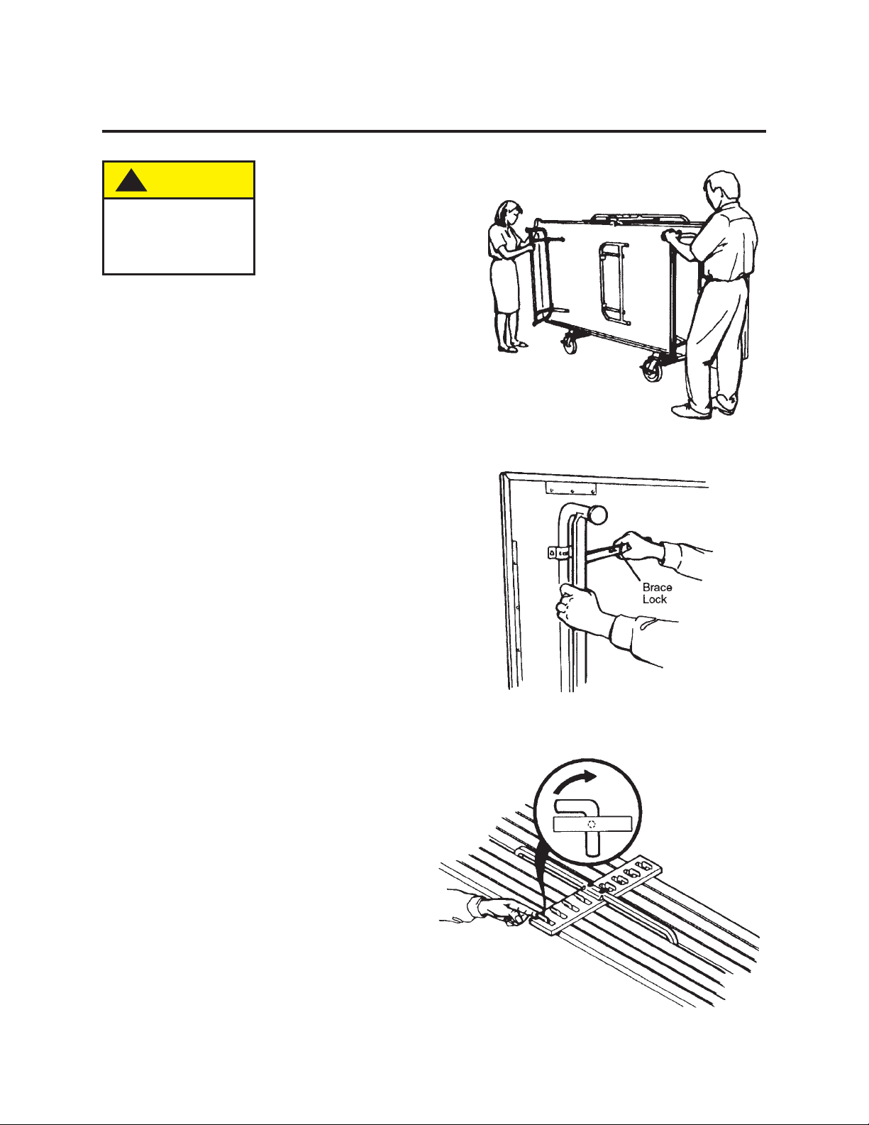
REMOVING THE PLATFORM UNITS
FROM THE
CART
1. Be sure the platform units are secured
to the cart before moving. Position the
cart near the set up area.
2. Open all legs on the outside platform
unit before removing from the cart.
3. Straighten the hinged brace on each
leg. If necessary, push in on the brace
lock until it engages.
4. With a 6 or 8-Unit Cart, release the first
platform unit by pushing the unit lock to
the right.
!
CAUTION
To avoid injury, two
people should set
up the platforms.
6
Page 7
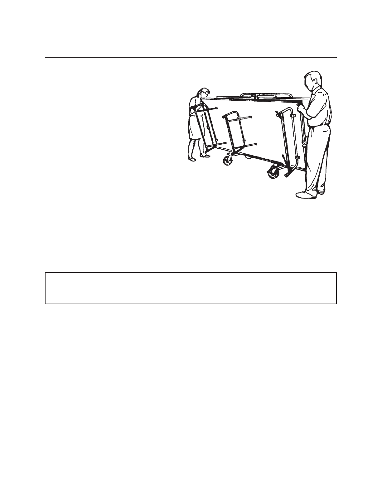
SETTING UP INDIVIDUAL PLATFORM UNITS (CONTINUED)
5. Rotate the platform unit off the cart and set it upright on its legs.
6. Repeat steps 2 - 5 for the remaining platform units.
If all of the platform units being set up are same-height platforms, go to page 8.
If setting up platform units as riser systems or as a multilevel stage, go to page 13.
7
Page 8
8
TROUPER SAME-HEIGHT PLATFORM SYSTEMS
CONNECTING SAME-HEIGHT PLATFORMS
1. Position the first two platform units at their desired stage location (at the rear center of the stage).
2. Attach them together in at least two places, using the unit-to-unit clamps beneath the platform
surface.
3. Attach the remaining platform units together in the same way.
!
WARNING
Platforms are
unsafe if unit-tounit clamps are not
used as specified.
Page 9
9
INSTALLING GUARD RAILS
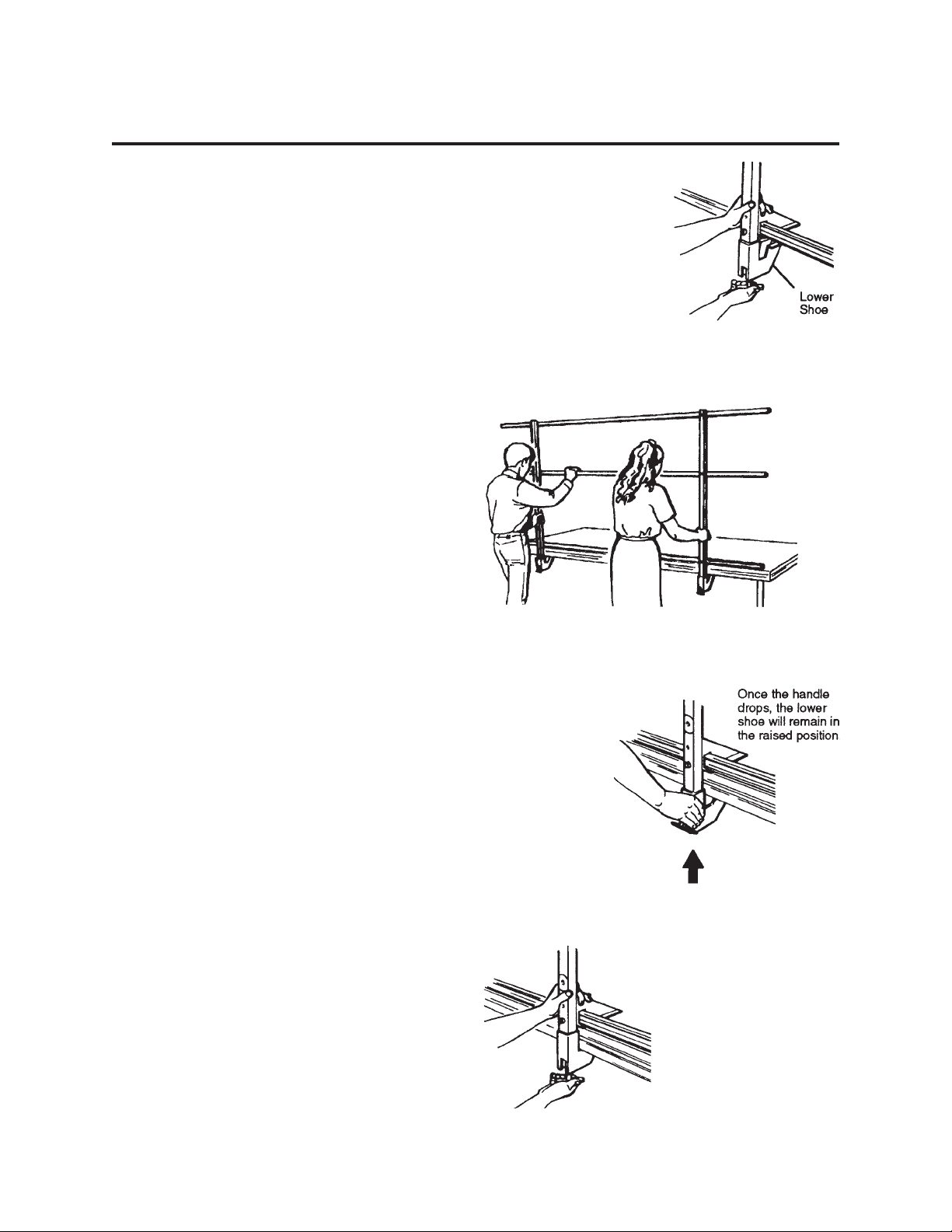
To attach each guard rail assembly to the platform
system:
1. Unscrew the handle at the bottom of each
upright, just until pulling the handle outward
allows the lower shoe to drop. Don’t unscrew
all the way.
2. Set the guard rail on the platform, with the
lower shoe on each upright positioned below
the deck surface. Center the rail side-to-side
on the platform section.
3. Lift the lower shoe on each upright until the
handle drops.
4. Slide the Rail against the platform deckand
turn the handle until the lower shoe is tight
against the platform deck.
Page 10
10
INSTALLING DRAPERY ENCLOSURES
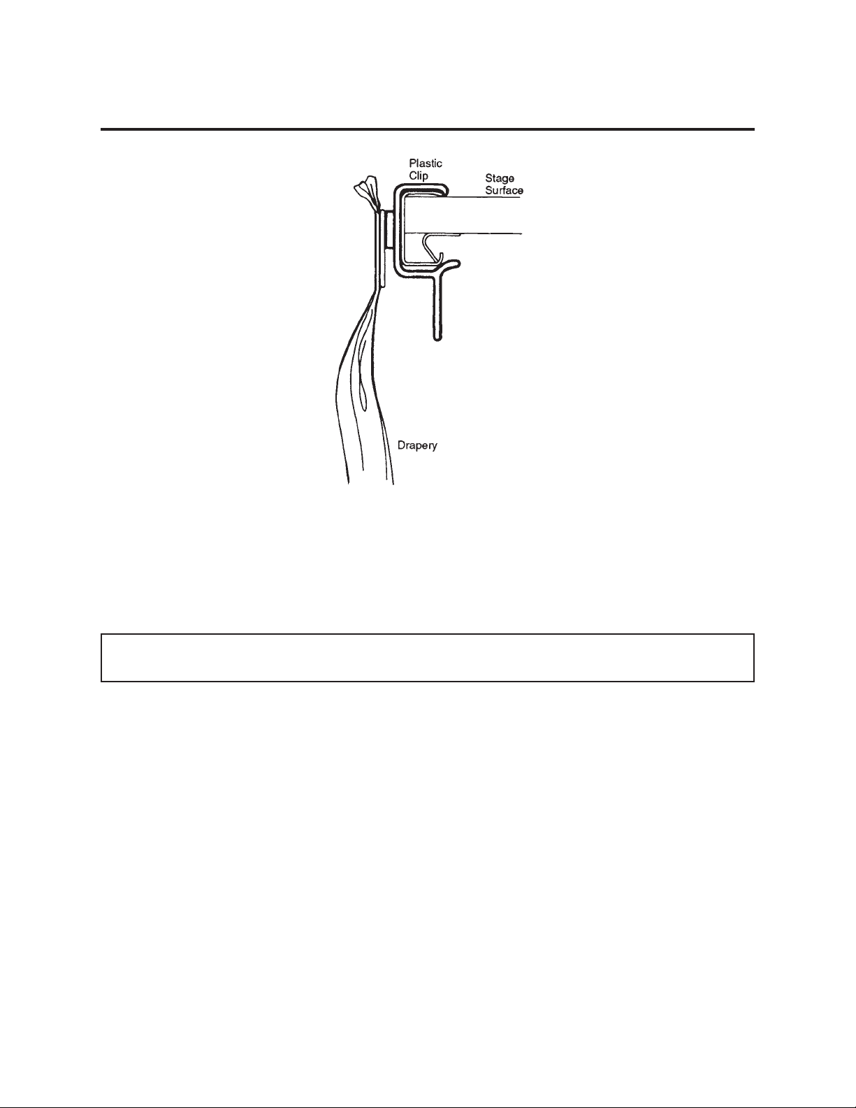
Draperies are often used to close off the lower portion of the stage, for better appearance. They can be
attached to the stage even where stairways or back/side rails are used.
The draperies are secured to the stage using plastic clips fitted with a hook tab that connects to a loop
fastener on the drapery.
Drapery enclosures must be attached after guard rails are installed, and before stairways.
To attach the draperies:
1. Install clips along the stage perimeter wherever drapery is desired (about 12" apart).
2. Beginning at a corner of the stage, press the drapery onto the clips.
3. Continue attaching the drapery to the clips until the section is completely installed.
4. Repeat the above procedure with the remaining drapery sections.
Page 11

11
INSTALLING THE STAIRWAY(S)
The 2-step and 3-step stairways supplied with
Trouper Platform Systems can be adapted to
several staging models and heights.
The hook tube assemblies that slip into
guides on each side of the stairway frame
have a notched plate which can be
interchanged to match the framework on the
bottom of the staging. The illustration shows
the appropriate notched plate properly
mounted for use with Trouper Platform
Systems.
Each stairway model can be adjusted for two
platform heights:
• The 2-step stairway can be adjusted for
16" or 24" platform heights
• The 3-step stairway can be adjusted for
24" or 32" platform heights.
When the snap button on the hook tube
assembly is in the matching hole in the guide,
the stairway can be connected to the higher
platform. When the hook tube assembly is all
the way down in the guide, the stairway can
be connected to the lower platform.
The notched plates must be on the outside of
the tubes, extending away from the stairway
frame.
To attach the stairway:
1. Be sure that the stairway has the correct
hook tube assemblies (see above).
2. Adjust the hooks to the proper height for
the stage.
3. Tip the stairway into place.
4. Check that the notch in the hook tube is
secured to the stage framework, and that
the stairway feet are flat on the floor.
5. Tuck the top edge of drapery enclosures
under the lip of the stage at stairway
locations.
Page 12
12
INSTALLING A BACKDROP
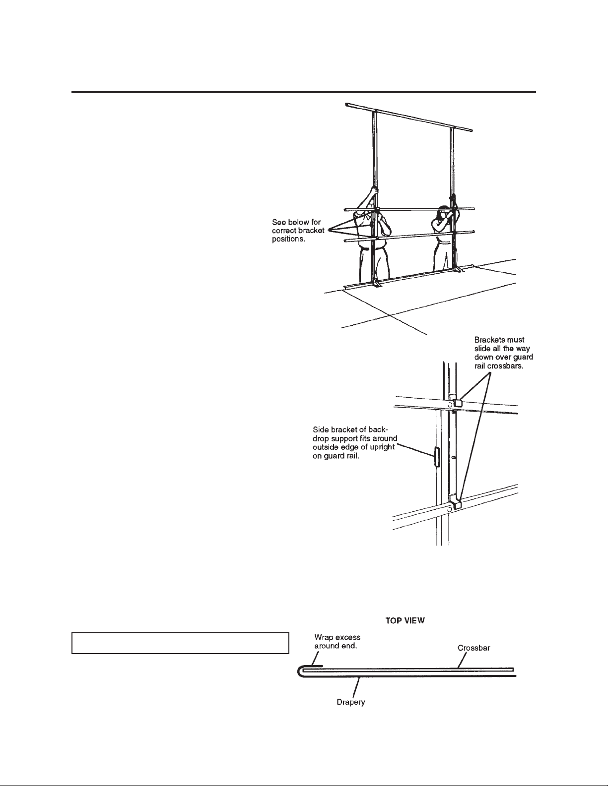
NOTE: Two people are required to install the
backdrop support.
1. Unfold each backdrop support and set it on
a guard rail as shown.
2. Hook-and-loop tape is attached to both
surfaces so that drapery sections can be
secured to the crossbar of the backdrop
support.
Use a ladder to attach the drapery. Wrap
any excess drapery around the end of the
crossbar.
For disassembly instructions, see page 20.
Page 13
13
TROUPER RISER PLATFORM SYSTEMS
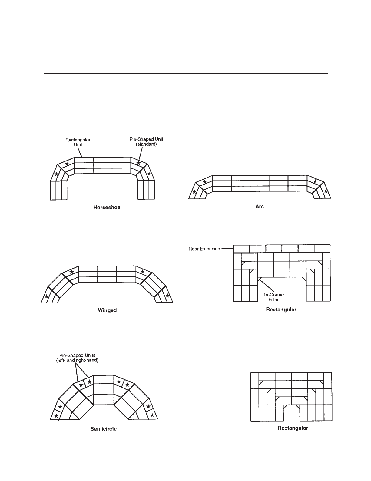
TYPICAL RISER LAYOUTS
Use rectangular and pie-shaped units as shown.
At the third elevation of pie-shaped locations:
-Choral risers have a single unit
-Band risers have two units, one left-hand and one right-hand. If a fourth elevation has been
supplied, both choral and band risers will have two units, one left-hand and one right-hand.
Page 14
14
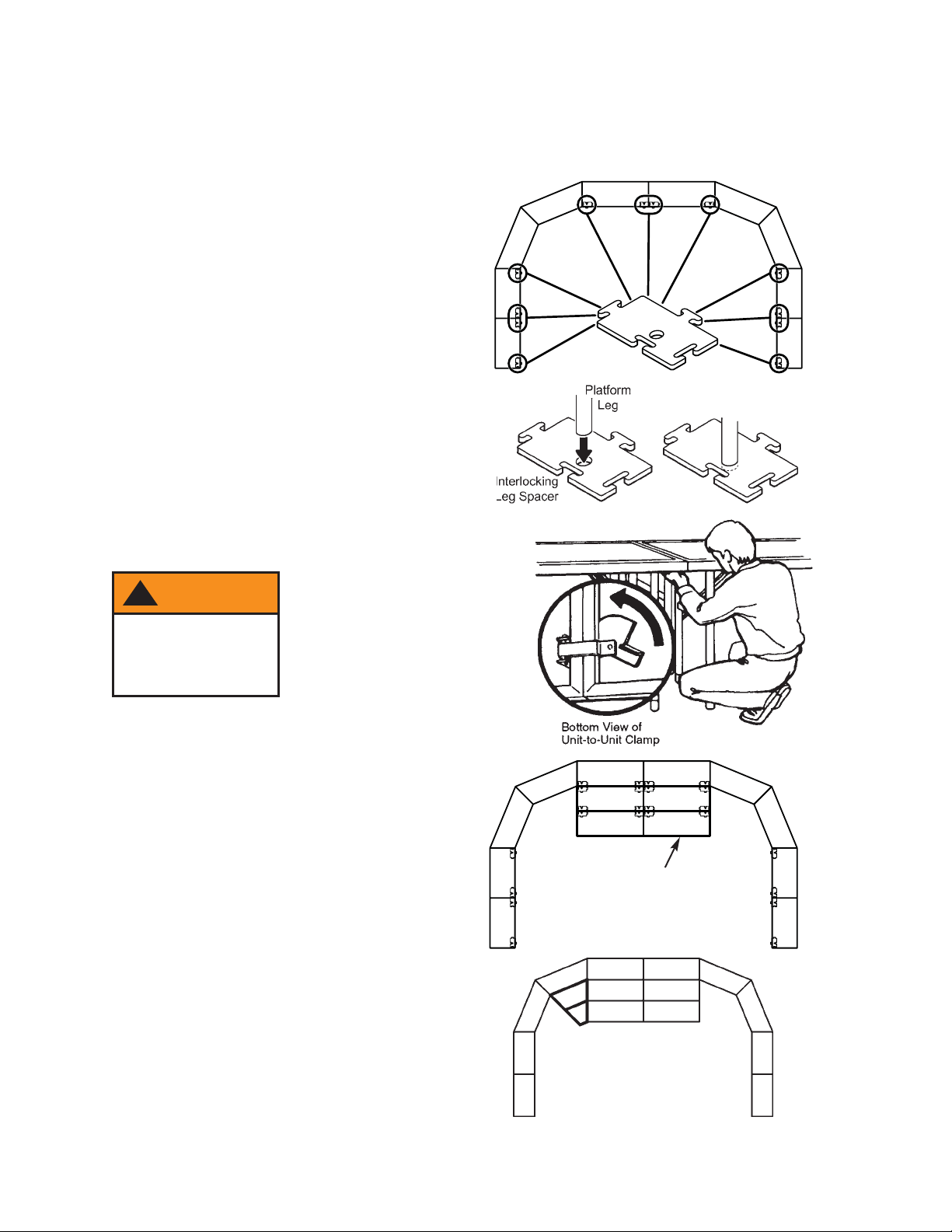
CONNECTING RISER SECTIONS
1. Set up the back row of platforms (including
any rear extensions), to verify that there is
enough space for the full riser set. Do not
lock these units together until the
remaining units are positioned.
2. Place interlocking leg spacers on the floor
under the inside legs of the rectangular
units as shown in the illustration. Platform
legs fit into the hole in the center of the
spacer.
Note: Interlocking leg spacers are used
only to connect rectangular platform units
together. Use metal spacer assemblies to
connect pie-shaped platform units together
as decribed on the following page.
3. Attach adjoining units together in at least
two places, using the unit-to-unit clamps
beneath the platform surface.
4. Position the remaining units for the center
section — first the middle elevation (16"),
then the front (8"). Repeat the pattern for
the interlocking leg spacers on the
rectangular units.
5. Assemble the next section (pie-shaped
units) to the left of the completed section,
again starting with the highest elevation
and working down to the lowest elevation.
!
WARNING
Platforms are
unsafe if unit-tounit clamps are not
used as specified.
Position the remaining
center units next
Page 15
15
CONNECTING RISER SECTIONS (CONTINUED)
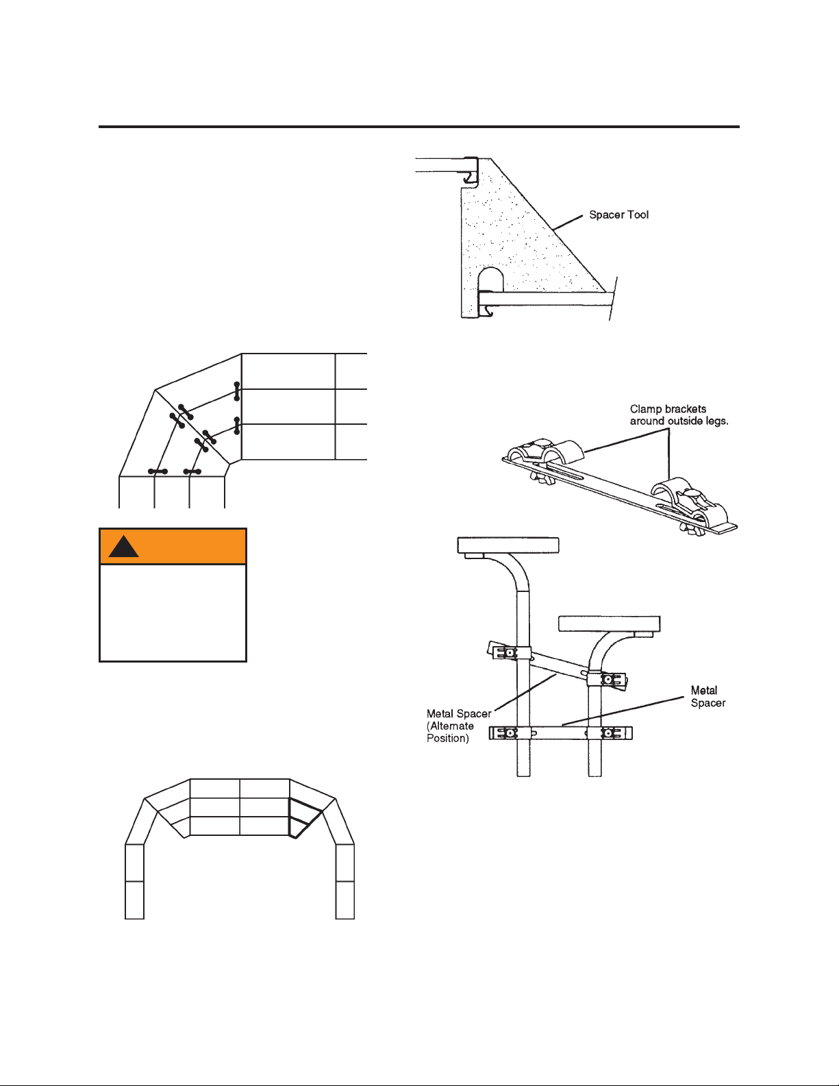
6. Use the riser spacer tool to align the
edges of the pie-shaped units vertically.
Make sure the corners of the decks are
aligned.
7. Connect all matching height units together
using the unit-to-unit clamps.
8. Connect different height pie-shaped units
together using metal spacer assemblies.
9. Assemble the next section ( pie-shaped
units) to the right of the completed
sections, again repeating steps 6 - 8 and
connecting same-height sections with the
unit-to-unit clamps.
9. Continue until all sections are installed.
!
WARNING
Always install all leg
spacers, and secure
each section with
unit-to-unit clamps,
before beginning a
new section.
Page 16
16
CONNECTING RISER SECTIONS (CONTINUED)
I
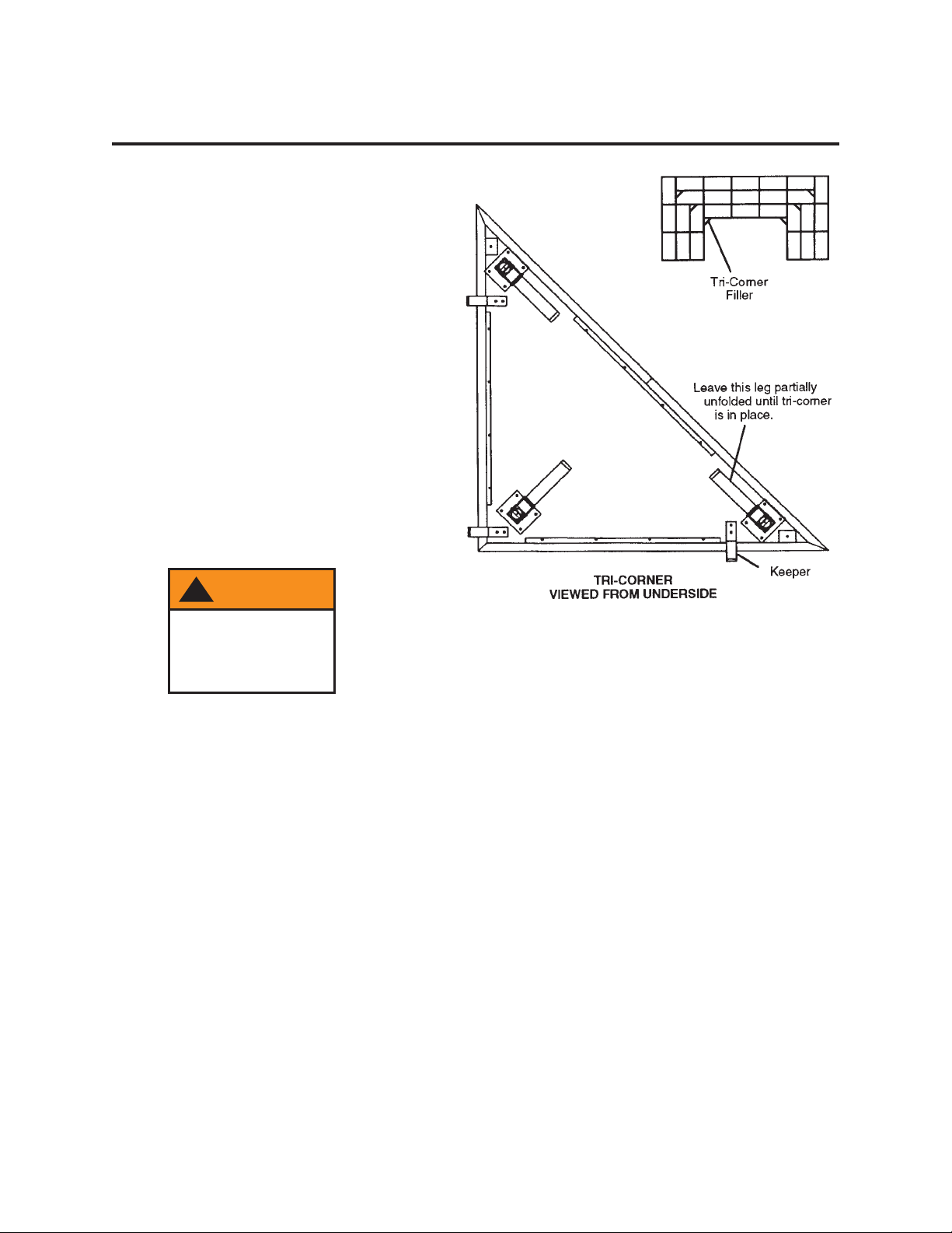
NSTALL TRI-CORNER FILLERS (IF USED)
10. Tri-corner fillers are used to fill corner voids in
rectangular configurations. To install them:
a. Unfold the two legs on the side that has
two keepers, until they lock in place.
Partially unfold the third leg (don’t lock
it).
b. Set the tri-corner approximately in place,
and raise the corner with the unfolded leg
until the two keepers will slide under the
edging of the opposite riser. Push the tricorner tight against that riser.
Lower the corner until the single keeper
will slide under the edging of the adjacent
riser. Slide the tri-corner until it contacts
the riser.
Raise the corner. Lower and lock the third
leg.
Make sure that all legs are locked in their
open position.
!
WARNING
Tri-corner fillers
can easily tip if not
properly secured.
Page 17

17
INSTALLING CLOSURE PANELS
There are two styles of closure panels:
• Those that go between the different levels
of units (elevation closures). They have
positioning brackets along the top edge.
• Those that touch the floor (along the front
of the bottom row, and the side closure
panels). They have clips along the top
edge to snap the closure onto the unit.
To simplify installation, the closures are
labeled (on the back side) by a letter that
indicates their length and position. See the
illustration.
Note: On some rectangular riser sets, there
may also be various odd-length closure
panels that are not labeled.
It is suggested that you install any 8' and 6'
closures first. This will make it easier to
identify where the smaller closures mount.
INSTALLING CHAIR STOPS
The riser was shipped with enough chair stops
to span the back of all elevations on the risers,
plus the sides of end units that are 16" or
higher.
Chair stops cannot be installed where closure
panels or guard rails are used.
Any excess chair stop may be discarded.
To install chair stops:
1. Snap chair stop clips onto every unit,
where appropriate, at approximately 24"
intervals.
Note: Side closures must be installed after
the clips, but before the chair stops are
installed. See “Installing Closure Panels”
above.
2. Install the chair stops into the clips, with the
grooved side up.
Page 18

18
INSTALLING CLOSURE PANELS (CONTINUED)
FRONT FLOOR-LEVEL CLOSURES
1. Interlocking leg spacers must be installed
on the front row of platform legs to provide
a backstop for the front floor closure panels.
2. Snap the panels onto the riser unit. Inside
edge should be flush with interlocking leg
spacer for support.
ELEVATION CLOSURES
Install the panels from the middle of the riser
set, and then work your way toward the ends.
This will even out any gaps between the
elevation closures and the side closure panels.
1. Hook the lower clips onto the lower
elevation units at the same intervals as the
positioning brackets that came installed on
the closure panel.
2. Set the closure panel onto the clips, then
push the closure panel down and rotate it
until the positioning brackets catch the
upper elevation unit.
S
IDE CLOSURES
Snap the panels onto the sides of the riser set
(in the same way as the front floor-level
closures).
Note: Chair stop clips must be installed before
the side closures; chair stops must be installed
after the side closures. See “Installing Chair
Stops” on page 17.
Page 19

19
INSTALLING GUARD RAILS
To attach each guard rail assembly to the platform
system:
1. Unscrew the handle at the bottom of each
upright, just until pulling the handle outward
allows the lower shoe to drop. Don’t unscrew
all the way.
2. Set the guard rail on the platform, with the
lower shoe on each upright positioned below
the deck surface. Center the rail side-to-side
on the platform section.
3. Lift the lower shoe on each upright until the
handle drops.
4. Slide the Rail against the platform deckand
turn the handle until the lower shoe is tight
against the platform deck.
Page 20

20
DISASSEMBLING THE PLATFORM SYSTEM
1. To remove the drapery from a backdrop:
a. “Peel” the drapery away from the crossbar.
b. Fold the drapery carefully to minimize
wrinkling in storage.
An optional carrying case can be purchased
from Wenger to store the drapery.
c. Press the release button on each upright,
and lift the backdrop support from the guard rail.
2. Remove any stairways by lifting the outer end
(lowest step) until the hook tube assembly is
free of the stage.
3. Remove any drapery enclosures by reversing
the installation procedure. See “Installing
Drapery Enclusures” on page 10.
Don’t remove the clips from the drapery
unless they have to be relocated. Keeping
the clips on the drapery prevents lossing
them and eliminates the need to store separately.
If the clips remain attached to the platform
frame they will interfere with storage of the
platform units.
Carefully fold the drapery to minimize wrinkling. Special drapery hangers are available from Wenger.
4. Remove any guard rails by unscrewing the handles. Store the guard rails on the (optional) guard rail
storage cart.
5. Remove all closure panels.
6. Remove all chair stops.
IMPORTANT: Two people are recommended for the following step.
7. Release the unit-to-unit clamps on the underside of adjacent same-height platforms.
See “Connecting Same-Height Platforms” on page 8.
8. Pull the first platform section away from the stage or riser and place near the storage cart.
Tilt the section onto the cart.
9. Return the legs to their shorter position (if extended on dual-height models).
10. To fold the legs:
a. On each leg brace, slide the brace lock away from the deck,
and use the heel of your other hand to unlock the brace.
b. Fold the legs against the deck.
11. Be sure the platform units are positioned securely on
the cart:
a. On 12-Unit Carts, slide the end of the platform units
all the way into the guides on the handle end.
b. On 6- or 8-Unit Carts, secure each platform unit
with the unit lock.
c. On 3-Unit Carts, the platform units rest against the
diagonal brace.
10. Repeat steps 8 through 11 for the remaining sections.
Page 21

21
LOADING THE STORAGE CARTS
Wenger storage carts are available to store and transport 3, 6, 8, or 12 platform units. All cart models
store the platform units vertically, so that they can be tipped off the cart directly into their setup position.
See “Setting Up Individual Platform Units” on page 6).
• On the 3-Unit Cart, platform units rest against the diagonal brace.
• On the 6 and 8-Unit Carts, platform units are secured by the latches of the unit lock assembly at the
top of the cart.
Note that the height of the top cross tube on 6- and 8-Unit Carts can be adjusted to fit platform units
that are either 3' or 4' wide.
• On the 12-Unit Cart, platform units are secured by slipping them into the guides on the upright
handle assembly.
!
WARNING
Always use unit
locks when moving
or storing.
Page 22

22
MAINTENANCE
STAGE
SURFACE
Trouper platform units are available with the following surfaces:
• hardboard
• skid-resistant
• carpeted.
Clean and protect hardboard surfaces as you would any normal flooring. Clean skid-resistant surfaces by
sweeping with a broom. Spot-clean carpeting, keeping it as dry as possible — never saturate the carpet.
DRAPERY ENCLOSURES AND BACKDROPS
Drapery sections may be washed or dry-cleaned. Remove all drapery clips prior to cleaning.
Machine-wash at 120° F or lower using mild detergent. Remove immediately after the wash cycle is
completed.
Tumble-dry at “permanent-press” or lower temperature. Remove and hang immediately to prevent
wrinkling. Excessive heat or drying time will detract from the permanent-press characteristics of the
fabric.
Little or no ironing is required.
When dry-cleaning, tumble-dry on the lowest heat cycle and remove immediately when dry.
OTHER PREVENTIVE MAINTENANCE
Inspect all bolts on the stage and accessories every six months, and tighten as necessary.
Replace any worn, bent, or broken parts promptly to prevent injury.
REPLACEMENT PARTS LIST
Replacement parts for your Trouper Platform System can be ordered from Wenger Corporation by:
Phone: USA, (800) 733-0393
International, (507) 455-4100 collect
Fax: (507) 455-4258
Mail: The Wenger Corporation
P.O. Box 448
555 Park Drive
Owatonna, Minnesota, USA 55060-0448
When ordering replacement parts, always indicate the product name and model.
Items not shown on the following pages:
When ordering additional backdrop or enclosure draperies, indicate height, width, and color.
Replacement parts are not available for the basic platform units: order complete new units.
Page 23

23
REPLACEMENT PARTS LIST (CONTINUED)
P
LATFORM DECK
Item Qty Description
2 2 Leg assembly, outside
3 1 Leg assembly, inside
9 6 Bracket, leg pivot
10 6 Plug, leg tip, fixed-height
10 6 Plug, leg tip, dual-height
11 3 Screw, Phillips pan-head, 8 - 18 x 1/2"
12 4 Lock assembly, unit-to-unit
16 6 Lock, brace
17 6 Spring, compression
Page 24

24
REPLACEMENT PARTS LIST (CONTINUED)
2 AND 3-STEP STAIRWAYS
3-STEP MODEL
SHOWN
Item Qty
2-Step
Qty
3-Step
Description
1 2 3 Step assembly
2 2 2 Frame assembly, hand-rail
3 2 2 Tube, hook (with notched plate)
4 1 1 Brace, cross
5 2 2 Wheel assembly
6 12 16 Nut, hex, 5/16 - 18
7 12 16 Bolt, carriage, 5/16 - 18 x 1-1/2"
8 4 4 Screw, self-tapping, 1/4" x 3/4"
9 12 16 Washer, lock, 5/16”
Page 25

25
REPLACEMENT PARTS LIST (CONTINUED)
3-UNIT STORAGE CART
Item Qty Description Item Qty Description
1 1 Channel, caster, right-hand (with decal) 10 1 Tube, back frame
2 1 Channel, caster, left-hand 11 2 Bracket, pivot
3 2 Caster, swivel 12 6 Bolt, carriage, 5/16 - 18 x 2"
4 2 Caster, rigid 13 2 Strap, brace
5 12 Bolt, carriage, 5/16 - 18 x 5/8" 14 2 Angle, brace
6 30 Nut, lock, 5/16 - 18 15 4 Capscrew, 5/16 - 18 x 1"
7 2 Post assembly, upright 16 12 Washer, flat, 5/16"
8 1 Tube, cross 17 4 Capscrew, 5/16 - 18 x 1-3/4"
9 4 Capscrew, 5/16 - 18 x 2 - 1/4"
Page 26

26
REPLACEMENT PARTS LIST (CONTINUED)
6 AND
8-UNIT STORAGE CART
Item Qty Description Item Qty Description
1 2 Caster, swivel 8 1 Lock assembly, unit
2 2 Channel, caster 9 1 Tube, cross
3 16 Bolt, carriage, 5/16 -18 x 3/4" 10 2 Upright assembly
4 28 Nut, lock, 5/16 - 18 11 2 Caster, rigid
5 8 Bolt, carriage, 5/16 - 18 x 2-1/4" 12 2 Brace, center
6 4 Capscrew, 5/16 - 18 x 2" 13 16 Washer, lock, 5/16"
7 2 Washer, flat, 5/16"
Page 27

27
REPLACEMENT PARTS LIST (CONTINUED)
12-UNIT STORAGE CART
Item Qty Description
1 4 Capscrew, 3/8-16 x 2-1/4"
2 10 Nut, lock, 3/8 - 16
3 1 Bracket assembly, end
4 1 Frame assembly, base
5 2 Caster, swivel
6 2 Caster, rigid
7 6 Capscrew, 3/8 - 16 x 1"
Page 28

28
GUARD RAILS
Item Qty Description Item Qty Description
1 2 Upright Weldment4 9 4 Bolt, carriage, 5/16 - 18 x 3-1/4"
2 2 Lower Bracket Weldment 10 6 Nut, lock, 5/16 - 18
3 2 Bolt, tab, 3/8-16 11 1 Rail, chair [*]
4 2 Handle, tee 12 2 Rail, guard [*]
5 2 Plug, 1-1/2" square 13 1 Railing, In-Fill Panel
8 2 Capscrew, 5/16 - 18 x 3-1/2"
[*] Indicates rail length on order.
REPLACEMENT PARTS LIST (CONTINUED)
Page 29

29
G
UARD RAIL S
TORAGE TRUCK
Item Qty Description Item Qty Description
1 2 Channel, caster 8 12 Bolt, carriage, round-head, 5/16 - 18 x 2"
2 2 Brace, center (specify 6- or 8-unit) 9 2 Capscrew, 5/16 - 18 x 2"
3 2 Upright weldment 10 1 Rack assembly
4 2 Caster, swivel, 6" 11 4 Bracket, stabilizer
5 2 Caster, rigid, 6" 12 16 Bolt, carriage, 5/16 - 18 x 1"
6 6 Plug, 1-1/4" square 15 16 Washer, flat, 1/4"
7 30 Nut, lock, 5/16 - 18 16 2 Tube weldment, upright support
REPLACEMENT PARTS LIST (CONTINUED)
Page 30

30
D
RAPERY BACKDROP
SUPPORT
Item Qty Description
1 2 Upright Weldment
2 1 Tube, support
3 2 Bracket
4 4 Plug, 1-1/2" square
5 2 Plug, 1-1/4" square
6 2 Capscrew, 5/16 - 18 x 2"
7 2 Capscrew, 5/16 - 18 x 3-1/2"
8 4 Nut, lock, 5/16 - 18
9 2 Washer, flat, nylon, 5/16" I.D.
10 - Hook-and-loop strip, 101" long
REPLACEMENT PARTS LIST (CONTINUED)
Page 31

31
Page 32

32
Stagehand Platform Systems
Page 33

33
SAFETY PRECAUTIONS
SETUP
Insist that anyone who assists with the set up
the Stagehand Platform System be familiar with
this manual.
GUARD
RAILS
The guard rails are indicators of the perimeter of
the platform system, and are not intended as a
universal restraint. Excess weight or pressure
will cause them to collapse.
Never use the rails:
• As a crowd barrier
• As a perch
• As a tie-down.
PLATFORM STABILITY
All platform units must be locked together using
the unit-to-unit clamps beneath the stage
surface. These clamps are designed for onelevel stage sets. Do not set up a multilevel
stage using Stagehand units.
Stagehand platforms are designed for level
surfaces only and contain no provision for
leveling adjustments.
GAS SPRINGS
If you suspect that the gas springs on the cart
are not operating properly, contact the Customer
Service department at Wenger Corporation
immediately. NEVER use a platform that has
faulty springs!
!
CAUTION
To avoid injury,
some setup steps
may require two
workers.
!
WARNING
Cart is unsafe if gas
springs are not
operating properly.
Throughout this manual, you will find CAUTIONS and WARNINGS:
• WARNING means that if safety information is not followed someone could be seriously
injured or killed.
• CAUTION means that if safety information is not followed the platform could be damaged or
personal injury could result.
!
WARNING
Rails may collapse
if excess weight or
pressure applied.
!
WARNING
Platforms are
unsafe if unit-tounit clamps are not
used as specified.
Page 34

34
WARRANTY
Wenger Trouper Platform Systems are guaranteed free of defects in
materials and workmanship for five full years.
Our guarantee assures you of either a full refund or repair or
replacement of the defective materials or workmanship without charge,
at the discretion of our Customer Service Department. Just call a
Customer Service Representative at 1-800-733-0393 and state the
reason you are dissatisfied. If a product return is necessary, your
Representative will issue a return authorization. This is your sole remedy
for breach of this warranty.
Should you have a question or problem with any Wenger product, don’t
hesitate to call, even if the product is past warranty. It’s important to us
that all our customers be satisfied.
This is the sole warranty made by Wenger. Wenger disclaims all other
warranties, including the warranties of merchantability and fitness for a
particular purpose, as well as all liability for incidental, consequential,
special, and indirect damage. Wenger liability for direct damages shall
be limited to the amount you paid for the product involved. Wenger
reserves the right to make product changes without obligation to
incorporate such changes into products previously sold.
Some states do not allow the exclusion or limitation of damages or
warranties, so the above may not apply to you. This warranty gives you
specific legal rights. You may also have other rights which vary from
state to state.
Page 35

35
INTRODUCTION
Stagehand platform units are available in two fixed elevations (16" and 24"), as well as two dual-height
options (16/24" and 24/32").
Easily-attached 39" wide stairway units with double handrails are available in a 2-step version (for 16" or
24" stage heights) and a 3-step version (for 24" or 32" stage heights).
Guard rail assemblies should be used with all stage elevations, and are available in 3', 4', 6' and 8'
lengths. The to rail on all guard rails is located 42" above the platform surface. The rail assemblies
include a chair stop rail.
To give the stage a more formal, finished look, drapery skirting and drapery backdrops are also available
from Wenger.
UNPACKING OR SETTING UP FOR THE FIRST TIME
1. Remove all parts from their shipping cartons (refer to the packing list enclosed with the shipment).
Save the packaging materials at least until the stage system has been set up the first time.
2. Sort all platform units and accessories by size, leg length, etc.
3. Assemble all carts and stairways that are shipped disassembled - using the instructions supplied
with them.
4. If the platform units will be stored before being set up, see “Transporting and Storing Platform Units”
on page 43 and “Disassembling the Platform System” on page 42.
If the platform units will be set up immediately, see “Setting Up Individual Platform Units” on page 36.
IMPORTANT: Read this entire manual before you start to set up a platform system.
!
WARNING
Do not set up a
multilevel stage
using Stagehand
units.
Page 36

36
SETTING UP INDIVIDUAL PLATFORM UNITS
1. Bring the platform units to the set up area.
2. Open all legs on the platform units.
3. Straighten the hinged brace on each leg.
Pull the brace until the lock engages.
4. Dual-Height Models.
Adjust the legs to the desired height:
a. Pull the lower leg body out until the
locking tabs are visible (A).
b. Rotate the lower leg a quarter-turn (B).
c. Engage the locking tabs and lock them
into the upper leg body (C).
5. Depress the foot pedal with your left foot,
and gently push the unit down to the floor.
To keep the platform from rolling, maintain
firm pressure on the pedal.
Note: Units can be moved into their final
position by releasing the pedal just before
the legs rest on the floor. Once the unit is in
the desired location, depress the pedal
again and gently push the unit down until it
sets firmly in place. Lock the caster brakes.
Note: Stagehand platforms have locking
gas springs that are actuated only when the
pedal is fully depressed. If the pedal is
releasedl while raising or lowering the deck,
the gas springs lock and the deck won’t
move further up or down.
6. Repeat steps 2 - 5 for the remaining
platform units.
Page 37

37
CONNECTING SAME-HEIGHT PLATFORMS
1. Position the first two platform units in their desired stage location (in the rear center of the stage).
Attach them together in at least two places, using the unit-to-unit clamps beneath the platform deck.
2. Attach the remaining units together in the same way.
!
WARNING
Platforms are
unsafe if unit-tounit clamps are not
used as specified.
Page 38

INSTALLING GUARD RAILS
To attach each guard rail assembly to the platform
system:
1. Unscrew the handle at the bottom of each
upright, just until pulling the handle outward
allows the lower shoe to drop. Don’t unscrew
all the way.
2. Set the guard rail on the platform, with the
lower shoe on each upright positioned below
the deck surface. Center the rail side-to-side
on the platform section.
3. Lift the lower shoe on each upright until the
handle drops.
4. Slide the Rail against the platform deckand
turn the handle until the lower shoe is tight
against the platform deck.
38
Page 39

INSTALLING DRAPERY ENCLOSURES
39
Draperies are often used to close off the lower portion of the stage, for better appearance. They can be
attached to the stage even where stairways or back/side rails are used.
The draperies are secured to the stage using plastic clips fitted with a hook tab that connects to a loop
fastener on the drapery.
Drapery enclosures must be attached after guard rails are installed, and before stairways.
To attach the draperies:
1. Install clips along the stage perimeter wherever drapery is desired (about 12" apart).
2. Beginning at a corner of the stage, press the drapery onto the clips.
3. Continue attaching the drapery to the clips until the section is completely installed.
4. Repeat the above procedure with the remaining drapery sections.
Page 40

INSTALLING THE STAIRWAY(S)
The 2-step and 3-step stairways supplied with
Stagehand Platform Systems can be adapted
to several platform system models and
heights.
The hook tube assemblies that slip into guides
on each side of the stairway frame have a
notched plate which can be reversed to match
the framework on the bottom of the platform
deck. Select the hook tube assemblies that
have the notched plate in the illustration, and
install them as shown.
Each stairway model can be adjusted for two
platform heights:
• The 2-step stairway can be adjusted for
16" or 24" platform heights
• The 3-step stairway can be adjusted for
24" or 32" platform heights.
When the snap button on the hook tube
assembly is in the matching hole in the guide,
the stairway can be connected to the higher
platform. When the hook tube assembly is all
the way down in the guide, the stairway can
be connected to the lower platform.
The notched plates must be on the outside of
the tubes, extending forward from the stairway
frame.
To attach the stairway:
1. Be sure that the stairway has the correct
hook tube assemblies (see above).
2. Adjust the hook tube assemblies to the
proper height for the stage (see above).
3. Tip the stairway into place.
4. Check that the notch in the hook tube is
secured to the stage framework, and that
the stairway feet are flat on the floor.
5. Tuck the top edge of drapery enclosures
under the lip of the stage at stairway
locations.
40
Page 41

41
INSTALLING A BACKDROP
NOTE: Two people are required to install the
backdrop support.
1. Unfold each backdrop support and set it on a
guard rail as shown.
2. Hook-and-loop tape is attached to both surfaces
so that drapery sections can be secured to the
crossbar of the backdrop support.
Use a ladder to attach the drapery. Wrap any
excess drapery around the end of the crossbar.
Page 42

42
DISASSEMBLING THE PLATFORM SYSTEM
1. To remove the drapery from a backdrop:
a. “Peel” the drapery away from the crossbar.
b. Fold the drapery carefully to minimize
wrinkling in storage.
An optional carrying case can be purchased
from Wenger to store the drapery.
c. Press the release button on each upright,
and lift the backdrop support from the guard
rail.
2. Remove any stairways by lifting the outer end
(lowest step) until the hook tube assembly is
free of the stage.
3. Remove any drapery enclosures by reversing
the installation procedure. See “Installing
Drapery Enclusures” on page 39.
Don’t remove the clips from the drapery
unless they have to be relocated. Keeping
the clips on the drapery prevents lossing
them and eliminates the need to store
separately.
If the clips remain attached to the platform
frame they will interfere with storage of the
platform units.
Carefully fold the drapery to minimize wrinkling.
Special drapery hangers are available from
Wenger.
4. Remove any guard rails by unscrewing the
handles.
Store the guard rails on the (optional) guard rail
storage cart.
5. Release the unit-to-unit clamps on the
underside of adjacent same-height platforms.
See “Setting up Individual Platform Units” on
page 36.
6. Depress the foot pedal with your left foot, and
lift the deck to its vertical position. Be sure it is
resting in both saddles, then release the pedal.
Unlock the caster brakes.
Do not pull up on the deck too quickly, or the
unit could overturn.
!
CAUTION
Unit can overturn if
pedal is released
before deck rests in
saddles.
!
CAUTION
Unit can overturn if
deck is lifted too
quickly.
Page 43

43
DISASSEMBLING THE PLATFORM SYSTEM (CONTINUED)
7. Return the legs to their shorter position (if extended
on dual-height models).
8. To fold the legs:
a. One each leg brace, slide the brace lock away
from the deck, then use the heel of your other
hand to unlock the brace.
b. Fold the legs against the deck.
9. Repeat steps 5 to 8 for the remaining sections.
TRANSPORTING AND STORING PLATFORM UNITS
TRANSPORTING
To transport platform units to the storage area, roll them by pushing from the end.
If necessary, units can also be safely lifted and carried when in the transport position. For safe handling,
two people are required. Grasp the ends of the deck — not the cart.
STORING
The platform units will nest together for compact storage.
Page 44

44
MAINTENANCE
STAGE
SURFACE
Stagehand platform units are available with the following surfaces:
• hardboard
• skid-resistant
• carpeted.
Clean and protect hardboard surfaces as you would any normal flooring. Clean skid-resistant surface by
sweeping with a broom. Spot-clean carpeting, keeping it as dry as possible — never saturate the carpet.
DRAPERY
ENCLOSURES AND BACKDROPS
Drapery sections may be washed or dry-cleaned. Remove all drapery clips prior to cleaning.
Machine-wash at 120° F or lower using mild detergent. Remove immediately after the wash cycle is
completed.
Tumble-dry at “permanent-press” or lower temperature. Remove and hang immediately to prevent
wrinkling. Excessive heat or drying time will detract from the permanent-press characteristics of the
fabric.
Little or no ironing is required.
When dry-cleaning, tumble-dry on the lowest heat cycle and remove immediately when dry.
GAS SPRINGS
If you suspect that the gas springs on the cart are not operating properly, contact the Customer Service
department at Wenger Corporation immediately. NEVER use the platforms that have faulty springs!
O
THER PREVENTIVE
MAINTENANCE
Inspect all bolts on the stage and accessories every six months, and tighten as necessary.
Replace any worn, bent, or broken parts promptly to prevent injury.
REPLACEMENT PARTS LIST
Replacement parts for your Trouper Platform System can be ordered from Wenger Corporation by:
Phone: USA, (800) 733-0393
International, (507) 455-4100 collect
Fax: (507) 455-4258
Mail: The Wenger Corporation
P.O. Box 448
555 Park Drive
Owatonna, Minnesota, USA 55060-0448
When ordering replacement parts, always indicate the product name and model.
Items not shown on the following pages:
When ordering additional backdrop or enclosure draperies, indicate height, width, and color.
Replacement parts are not available for the basic platform units: order complete new units.
Page 45

45
REPLACEMENT PARTS LIST (CONTINUED)
PLATFORM
DECK
Item Qty Description
2 2 Leg assembly, outside
3 1 Leg assembly, inside
9 6 Bracket, leg pivot
10 6 Plug, leg tip, fixed-height
10 6 Plug, leg tip, dual-height
11 3 Screw, Phillips pan-head, 8 - 18 x 1/2"
12 4 Lock assembly, unit-to-unit
16 6 Lock, brace
17 6 Spring, compression
Page 46

46
REPLACEMENT PARTS LIST (CONTINUED)
P
LATFORM CART
Item Qty Description Item Qty Description
1 1
Cart Weldment
16 2
Spring, torsion
2 2
Arm, swing
17 1
Sleeve, foam
3 4
Spacer, short
18 2
Capscrew, 1/4 - 20 x 1-3/4"
4 2
Capscrew, 1/2 - 13 x 3"
19 2
Capscrew, 5/16 - 18 x 3-3/4"
5 2
Nut, lock, 1/2 - 13
20 2
U-channel, extruded rubber
6 1
Crosstube Weldment
21 2
Pad, rubber, saddle
7 4
Capscrew, 1/4 - 20 x 3/4"
23 6
Plug, plastic, 1" x 1-1/2"
8 6
Nut, lock, 1/4 - 20
24 2
Bushing, nylon
9 2
Caster, swivel, 4" dia.
25 2
Capscrew, 5/16 - 18 x 3-1/2"
10 2
Spring, gas, locking
26 4
Nut, lock, 5/16 - 18
11 2
Clevis, gas spring
27 2
Bracket, channel
12 2
Plate, pivot, gas spring
28 2
Capscrew, 1/4 - 20 x 3"
13 4
Nut, hex, M10 x 1
29 16
Screw, Phillips pan-head, #10 x 3/4"
14 2
Cam, pedal bar
30 2
Caster, braked, 4" dia.
15 1
Tube, pedal
Page 47

47
REPLACEMENT PARTS LIST (CONTINUED)
2- AND
3-STEP STAIRWAYS
3-Step Model Shown
Item Qty
2-Step
Qty
3-Step
Description
1 2 3 Step assembly
2 2 2 Frame assembly, hand-rail
3 2 2 Tube, hook (with notched plate)
4 1 1 Brace, cross
5 2 2 Wheel assembly
6 12 16 Nut, hex, 5/16 - 18
7 12 16 Bolt, carriage, 5/16 - 18 x 1-1/2"
8 4 4 Screw, self-tapping, 1/4" x 3/4"
9 12 16 Washer, lock, 5/16”
Page 48

REPLACEMENT PARTS LIST (CONTINUED)
GUARD RAILS
48
Item Qty Description Item Qty Description
1 2 Upright Weldment 9 4 Bolt, carriage, 5/16 - 18 x 3-1/4"
2 2 Lower Bracket Weldment 10 6 Nut, lock, 5/16 - 18
3 2 Bolt, tab, 3/8-16 11 1 Rail, chair [*]
4 2 Handle, tee 12 2 Rail, guard [*]
5 2 Plug, 1-1/2" square 13 1 Railing, In-Fill Panel
8 2 Capscrew, 5/16 - 18 x 3-1/2" 14 4 Plug, 1-1/8" square
[*] Indicates rail length on order.
Page 49

49
REPLACEMENT PARTS LIST (CONTINUED)
GUARD RAIL STORAGE TRUCK
Item Qty Description Item Qty Description
1 2 Channel, caster 8 12 Bolt, carriage, round-head, 5/16 - 18 x 2"
2 2 Brace, center (specify 6- or 8-unit) 9 2 Capscrew, 5/16 - 18 x 2"
3 2 Upright weldment 10 1 Rack assembly
4 2 Caster, swivel, 6" 11 4 Bracket, stabilizer
5 2 Caster, rigid, 6" 12 16 Bolt, carriage, 5/16 - 18 x 1"
6 6 Plug, 1-1/4" square 15 16 Washer, flat, 1/4"
7 30 Nut, lock, 5/16 - 18 16 2 Tube weldment, upright support
Page 50

REPLACEMENT PARTS LIST (CONTINUED)
DRAPERY BACKDROP SUPPORT
50
Item Qty Description
1 2 Upright Weldment
2 1 Tube, support
3 2 Bracket
4 4 Plug, 1-1/2" square
5 2 Plug, 1-1/4" square
6 2 Capscrew, 5/16 - 18 x 2"
7 2 Capscrew, 5/16 - 18 x 3-1/2"
8 4 Nut, lock, 5/16 - 18
9 2 Washer, flat, nylon, 5/16" I.D.
10 - Hook-and-loop strip, 101" long
Page 51

51
 Loading...