

Wenger Bravo Stand, Roughneck Stand, Classic 50 Stand, Preface Stand, Preface Conductor’s Stand Assembly And Owner's Manual
Page 1

Assembly and Owner's Instructions
Music Stands
Bravo® Stand
Roughneck® Stand
Classic 50® Stand
Preface® Stand
Preface® Conductor’s Stand
Contents
Important User Information . . . . . . . . . . . . . . . . . . . . . . . . . . . . . . 2
General .........................................2
Manufacturer .....................................2
Intended Use .....................................2
Warranty ........................................2
Required Tools. . . . . . . . . . . . . . . . . . . . . . . . . . . . . . . . . . . . . . . . 3
Parts List . . . . . . . . . . . . . . . . . . . . . . . . . . . . . . . . . . . . . . . . . . . . 3
Visit the Music Stands web page at wengercorp.com for more information.
Note: Please read and understand these instructions before assembling or using.
Note: If you need additional information, contact Wenger Corporation using the information below.
©Wenger Corporation 2018 Printed in USA 2018-07 Part #237A113-11
Assembly . . . . . . . . . . . . . . . . . . . . . . . . . . . . . . . . . . . . . . . . . . . . 4
Base and Slider Assembly ..........................4
Desk and Slider Assembly ..........................5
Operation . . . . . . . . . . . . . . . . . . . . . . . . . . . . . . . . . . . . . . . . . . . . 7
Storage . . . . . . . . . . . . . . . . . . . . . . . . . . . . . . . . . . . . . . . . . . . . . 8
Maintenance . . . . . . . . . . . . . . . . . . . . . . . . . . . . . . . . . . . . . . . . . 8
Wenger Corporation, 555 Park Drive, P.O. Box 448, Owatonna, Minnesota 55060-0448
Questions? Call.....USA: (800) 4WENGER (493-6437) • Worldwide: +1-507-455-4100 • wengercorp.com
Page 2

Important User Information
General
Copyright © 2018 by Wenger Corporation
All rights reserved. No part of the contents of this manual may be reproduced, copied, or transmitted in any form
or by any means including graphic, electronic, or mechanical methods or photocopying, recording, or information
storage and retrieval systems without the written permission of the publisher, unless it is for the purchaser’s
personal use.
Printed and bound in the United States of America.
The information in this manual is subject to change without notice and does not represent a commitment on the
part of Wenger Corporation. Wenger Corporation does not assume any responsibility for any errors that may
appear in these instructions.
In no event will Wenger Corporation be liable for technical or editorial omissions made herein, nor for direct,
indirect, special, incidental, or consequential damages resulting from the use or defect of these instructions.
The manufacturer reserves the right to change this product at any time.
The information in this document is not intended to cover all possible conditions and situations that might occur.
The end user must exercise caution and common sense when assembling or installing Wenger Corporation
products. If any questions or problems arise, call the Wenger Corporation at (800) 4WENGER (493-6437)
or +1-507-455-4100 worldwide.
Manufacturer
The Music Stands are manufactured by:
Wenger Corporation
555 Park Drive
Owatonna, MN 55060
(800) 4WENGER (493-6437) • +1 (507) 455-4100
wengercorp.com
Intended Use
· This product is intended for indoor use in normal ambient temperature and humidity
conditions — it must not be exposed to prolonged outside weather conditions.
· This product is intended to be assembled only as described in these instructions.
Warranty
This product is guaranteed free of defects in materials and workmanship for ve full years from date
of shipment. A full warranty statement is available upon request.
2
Page 3
Required Tools
The following tools are needed to assemble the Music Stands:
• Plastic or Wood Mallet
• 7/16” (11 mm) Box End or Socket Wrench
• 5/32” (4 mm) Hex Key Wrench
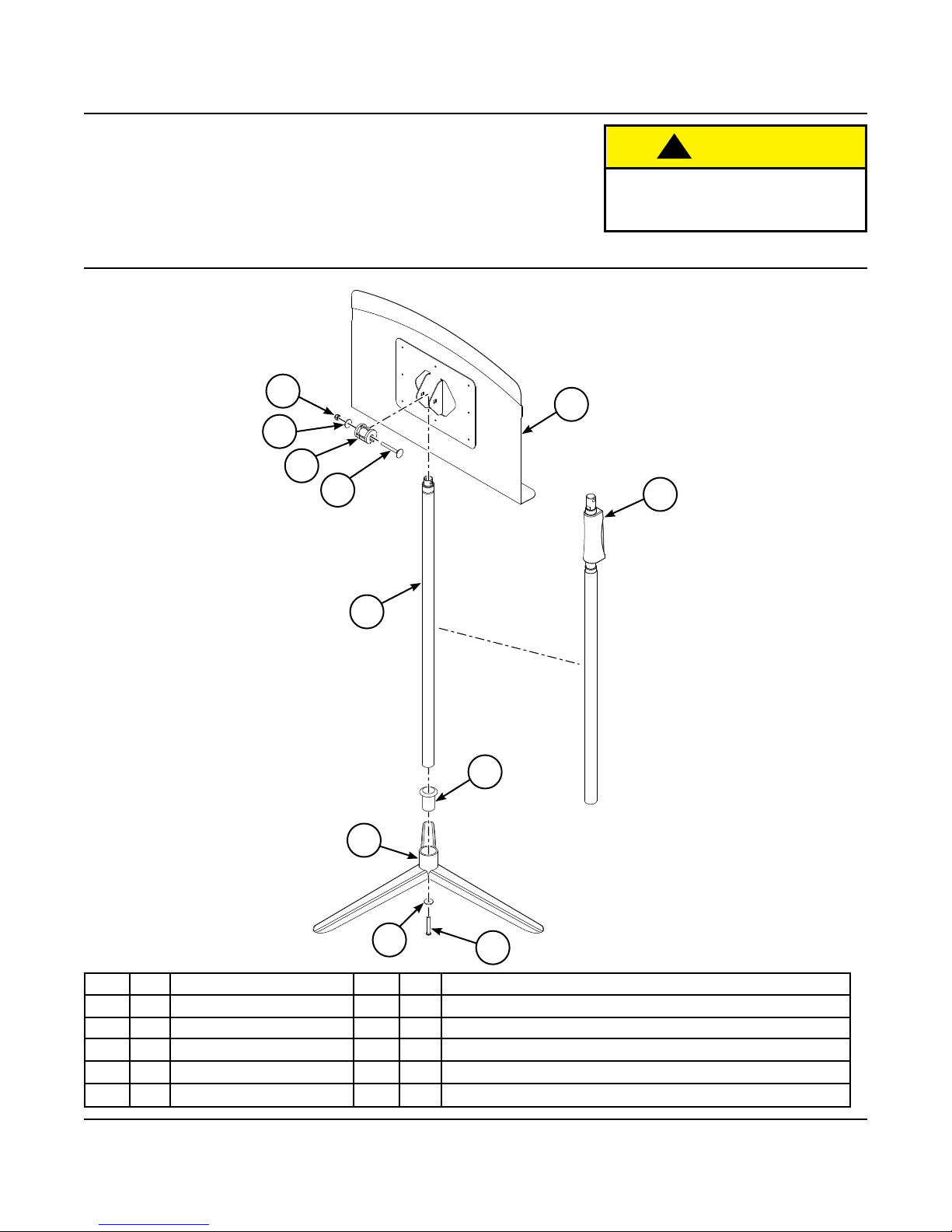
Parts List
!
CAUTION
Only use hand tools for assembly.
Power tools could damage the
components.
7
6
4
5
1
9
2
3
Trigger Lock is on
Roughneck Stand
ONLY
1
Item Qty Description Item Qty Description
1 1 Slider Assembly 6 1 Washer, 1/4” ID x 1” OD
2 1 Base Assembly 7 1 Lock Nut, Flange, BZ, 1/4-20”
3 1 Desk 8 1 Socket Screw, BHD, 1/4-20 x 1.25”
4 1 Pivot Hub 9 1 Bushing Insert (Roughneck and Preface Stands ONLY)
5 1 Elevator Bolt, 1/4-20 x 2” 10 1 Washer, 1/4” ID x 1” OD (Classic 50 Stand ONLY)
10
8
3
Page 4

Assembly
Base and Slider Assembly
If Assembling Roughneck or Preface Stands, begin at Step 1,
If Assembling Bravo or Classic 50 Stands, skip to Step 2.
!
CAUTION
Only use hand tools for assembly.
Power tools could damage the components.
1. Slide the Bushing Insert into the Base Assembly.
If necessary, tap the Bushing Insert with a plastic or wood mallet
to ensure it is seated tightly in the Base Assembly.
2. Push the Slider Assembly into the Base Assembly.
The Base Assembly may be tapped with a plastic or wood mallet until
the Slider Assembly is ush with the bottom of the Base Assembly.
!
CAUTION
Do not allow the Inner Tube to strike the ground.
Do not force the Slider Assembly into the
Base Assembly.
Damage to the components could occur.
Bushing
Insert
Base
Assembly
Roughneck and Preface Stands ONLY
Base
Assembly
Slider
Assembly
If Assembling Classic 50 Stands ONLY, go to Step 3,
For ALL other stands, skip to Step 4.
3. Place a 1/4” ID x 1” OD Washer on the 1/4-20 x 1.25” Socket Screw.
4. Attach the Base Assembly to the Slider Assembly using a
1/4-20 x 1.25” Socket Screw.
Tighten the Socket Screw using a 5/32” (4mm) hex key wrench until
the Slider Assembly no longer rotates inside of the Base Assembly.
Note: If assembling a Preface Conductor’s Stand, follow
these steps for both of the Base and Slider Assemblies.
Do Not Allow the
Inner Tube to
Strike the Ground
Washer
(Classic 50 Stand ONLY)
1/4-20 1.25”
Socket Screw
4
Page 5

Assembly (continued)
Desk and Slider Assembly
1. Extend the inner tube of the Slider Assembly 3” to 4” (76 to 102 mm) to ease installation of the Pivot Hub.
Insert an Allen Wrench through the holes at the end of the inner tube and use as a handle to extend the
tube. A pair of pliers may also be used to grasp the wall of the inner tube to aid in extending it.
!
CAUTION
Be sure not to distort the shape of the
inner tube with a pliers.
Damage to the components could occur.
2. Place the Pivot Hub over the Tube Assembly and align the holes in both.
Pivot
Hub
Assembly
3. Slide the Desk over the Pivot Hub and Tube Assembly with all sets of holes aligned.
Note: If assembling a Roughneck Stand, the Trigger Lock will
face toward the Desk.
Desk
Slider
Desk
Trigger Lock
(Roughneck Stand Only)
5
Page 6

Assembly (continued)
Desk and Slider Assembly (continued)
4. Slide the 1/4-20 x 2” Elevator Bolt through the aligned holes.
Be sure that the square shoulder of the Elevator Bolt slips into the square hole of the
Desk Flange or the Desk will not tighten properly.
Attach with the 1/4” ID x 1” OD Washer and 1/4-20” Lock Nut using a 7/16” (11 mm) box-end or
socket wrench to adjust the desk pivot tension, as necessary.
1/4-20
Lock Nut
1/4” ID x 1” OD
Washer 50
1/4-20 x 2”
Elevator Bolt
Square Shoulder
& Square Hole
Note: If assembling a Preface Conductor’s Stand, follow these steps for both Slider Assemblies.
5. Fully extend the Slider Assembly.
The inner surface of the outer tube is lubricated with a high pressure grease to extend the life
of the Music Stand and to prevent corrosion during shipping and storage.
Wipe o any excess grease from the inner tube with a rag or paper towel as needed.
This should only be necessary the rst time the Slider Assembly is fully extended.
6
Page 7

Operation
Use the Music Stand with care.
1. Move the Inner Tube of the Slider Assembly up or down to adjust the height of the Desk.
2. Pivot the Desk to the required angle.
Note: The tension for the desk angle can be tightened by adjusting the Nut on the Elevator Bolt.
Be sure that the square shoulder of the Elevator Bolt slips into the square hole of the
Desk Flange or the Desk will not tighten properly.
7
Page 8

Storage
Storage of the Music Stands is available by using the following accessories:
Large Stand Move and Store Cart
• 38 lbs (17 kg)
• Holds 18 Bravo Stands
• Holds 20 Roughneck Stands
• Holds 20 Classic 50 Stands
• Holds 20 Preface Stands without ipping desk
Maximize cart storage to hold 22 Preface Stands by ipping desk
• Large center pivot wheels for maneuverability
• Loads and unloads from both ends
Small Stand Move and Store Cart
• 21 lbs (9.45 kg)
• Holds 9 Bravo Stands
• Holds 10 Roughneck Stands
• Holds 10 Classic 50 Stands
• Holds 10 Preface Stands without ipping desk
Maximize cart storage to hold 11 Preface Stands by ipping desk
• Two-wheel cart design allows transport up and down stairs
Maintenance
1. Clean the music stand with a mild detergent.
Avoid using harsh or abrasive cleaning products.
2. Never apply oil or any lubricant to the Slider Assembly.
3. Periodically check fasteners to ensure that they have not loosened during use.
8
 Loading...