

Page 1
Assembly and Operation Instructions
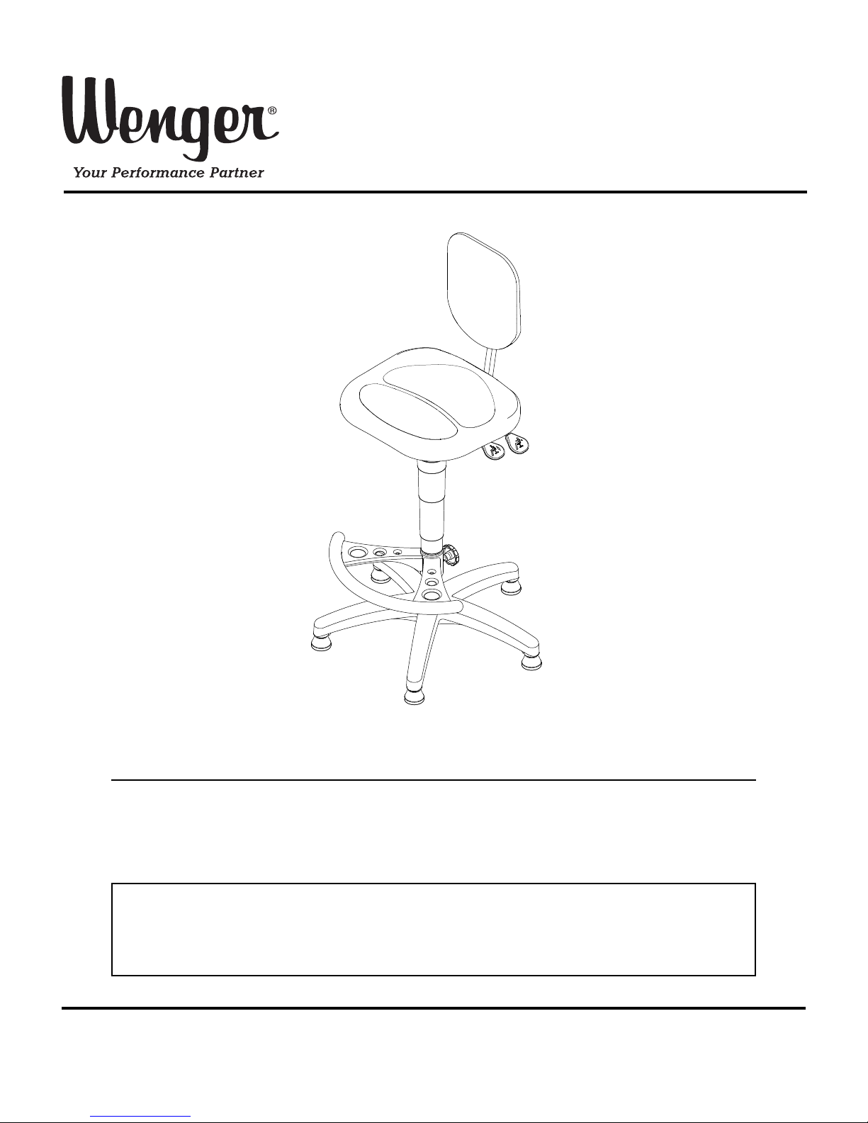
Nota®Conductor’s Chair
Note: Please read and understand these instructions before assembling the parts.
Note: Remove all items from the shipping cartons and arrange them in a convenient location.
Refer to the illustrations on the following pages. If you need additional information,
contact the Wenger Corporation using the information below.
CONTENTS
©Wenger Corporation 2014 Printed in USA 12/14 Part #157D209-02
Wenger Corporation, 555 Park Drive, P.O. Box 448, Owatonna, Minnesota 55060-0448
Questions? Call.....USA: 800-4WENGER (493-6437) • Worldwide: 1-507-455-4100 • www.wengercorp.com
Important User Information . . . . . . . . . . . . . . . . . . . . . . . . . . .2
General . . . . . . . . . . . . . . . . . . . . . . . . . . . . . . . . . . . . . .2
Manufacturer . . . . . . . . . . . . . . . . . . . . . . . . . . . . . . . . .2
Intended Use . . . . . . . . . . . . . . . . . . . . . . . . . . . . . . . . .2
Warranty . . . . . . . . . . . . . . . . . . . . . . . . . . . . . . . . . . . . .2
Parts List . . . . . . . . . . . . . . . . . . . . . . . . . . . . . . . . . . . . . . . . .3
Assembly . . . . . . . . . . . . . . . . . . . . . . . . . . . . . . . . . . . . . . . .4
Operation . . . . . . . . . . . . . . . . . . . . . . . . . . . . . . . . . . . . . . . .7
Page 2

2
IMPORTANT USER INFORMATION
GENERAL
Copyright © 2014 by Wenger Corporation
All rights reserved. No part of the contents of this manual may be reproduced, copied, or transmitted in
any form or by any means including graphic, electronic, or mechanical methods or photocopying,
recording, or information storage and retrieval systems without the written permission of the publisher,
unless it is for the purchaser's personal use.
Printed and bound in the United States of America.
The information in this manual is subject to change without notice and does not represent a commitment
on the part of Wenger Corporation. Wenger Corporation does not assume any responsibility for any
errors that may appear in this manual.
In no event will Wenger Corporation be liable for technical or editorial omissions made herein, nor for
direct, indirect, special, incidental, or consequential damages resulting from the use or defect of this
manual.
The information in this document is not intended to cover all possible conditions and situations that might
occur. The end user must exercise caution and common sense when assembling or installing Wenger
Corporation products. If any questions or problems arise, call Wenger Corporation at 1-800-733-0393.
MANUFACTURER
The Nota®Conductor’s Chair is manufactured for:
Wenger Corporation
555 Park Drive
Owatonna, MN 55060
1-800-4WENGER (493-6437) • 1-507-455-4100
www.wengercorp.com
INTENDED USE
• This product is intended for indoor use in normal ambient temperature and humidity conditions —
it must not be exposed to prolonged outside weather conditions.
• This product is intended to be assembled only as described in these instructions.
WARRANTY
This product is guaranteed free of defects in materials and workmanship for five full years from date
of shipment. A full warranty statement is available upon request.
Page 3
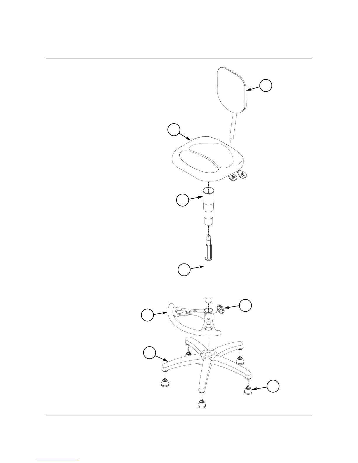
Item Qty Description
1 5 Glide
2 1 Base
3 1 Gas Cylinder
4 1 Foot Rest
5 1 Foot Rest Adjustment Knob
6 1 Telescoping Cover
7 1 Seat Assembly
8 1 Back Rest
3
PARTS LIST
2
3
1
6
4
8
7
5
Page 4

4
1. Press the five Glides (1) into the bottom of the Base (2).
2. Slide the Gas Cylinder (3) through the large hole in the Foot Rest (4).
3. Press the bottom of the Gas Cylinder into the center hole of the Base Assembly.
ASSEMBLY
Base
(2)
Glide
(1)
Gas Cylinder
(3)
Foot Rest
(4)
Page 5

4. Screw the Foot Rest Adjustment Knob (5) into the Foot Rest.
Do not fully-tighten yet.
5. Place the Telescoping Cover (6) over the top of the Gas Cylinder.
5
ASSEMBLY (CONTINUED)
Top of
Gas Cylinder
Telescoping
Cover
(6)
Foot Rest
Adjustment Knob
(5)
Page 6

6
ASSEMBLY (CONTINUED)
5. Place the Seat Assembly (7) over the top of the Gas Cylinder.
Rotate it as needed to align the three extruded profiles on the shaft of the
Gas Cylinder with the squared-off notches without screws.
Press the Seat Assembly onto the top of
the Gas Cylinder.
6. Slide the top of the Telescoping Cover (6)
up and snap it onto the bottom of the
Seat Adapter
7. Position the Foot Rest to be located under the front side of the
Seat Assembly and tighten the Foot Rest Adjustment Knob.
8. Keeping the Gas Cylinder at the lowest position,
carefully sit on the chair to apply additional pressure
to fully engage the components.
To check that all of the components are fully engaged,
hold onto the Seat Assembly and lift the chair.
The chair should remain assembled.
The Seat Height Adjustment Lever can be
used to adjust the Seat Assembly to a
higher position.
9. Press the Stop Release Button and insert the
post of the Back Rest (8) into the opening
at the back of the Seat Assembly.
Release the Back Height Adjustment Lever to allow
the post to completely slide through the opening.
Back
Rest
(8)
Back Height
Adjustment
Lever
Stop
Release
Button
Seat
Assembly
(7)
Top of
Gas Cylinder
Seat Height
Adjustment
Lever
Align the
Extruded Profiles with the
Squared-Off Notches
Top of
Telescoping
Cover
(6)
Bottom of
Seat Adapter
Seat Assembly not
shown for clarity.
Page 7

7
OPERATION
Page 8

8
OPERATION (CONTINUED)
 Loading...