

Page 1
Assembly Instructions and Owner’s Manual
Flex® TechBridge
Contents
Important User Information . . . . . . . . . . . . . . . . . . . . . . . . . . .2
Safety Precautions . . . . . . . . . . . . . . . . . . . . . . . . . . . . . . . . .2
Required Tools. . . . . . . . . . . . . . . . . . . . . . . . . . . . . . . . . . . . .3
Parts List . . . . . . . . . . . . . . . . . . . . . . . . . . . . . . . . . . . . . . . . .3
Note: Please read and understand the instructions before starting the assembly.
Note: Remove all items from the shipping cartons and arrange them in a convenient location.
Note: If you need additional information, contact Wenger Corporation using the information below.
©Wenger Corporation 2016 Printed in USA 07/16 Part #236A153-06
Wenger Corporation, 555 Park Drive, P.O. Box 448, Owatonna, Minnesota 55060-0448
Questions? Call.....USA: 800-4WENGER (493-6437) • Worldwide: 1-507-455-4100 • www.wengercorp.com
Assembly . . . . . . . . . . . . . . . . . . . . . . . . . . . . . . . . . . . . . . . . .4
Operation . . . . . . . . . . . . . . . . . . . . . . . . . . . . . . . . . . . . . . . . .7
Accessories (Sold Seperately) . . . . . . . . . . . . . . . . . . . . . . . .8
Page 2

Important User Information
General
Copyright © 2016 by Wenger Corporation
All rights reserved. No part of the contents of this manual may be reproduced, copied, or transmitted
in any form or by any means including graphic, electronic, or mechanical methods or photocopying,
recording, or information storage and retrieval systems without the written permission of the publisher,
unless it is for the purchaser’s personal use.
Printed and bound in the United States of America.
The information in this manual is subject to change without notice and does not represent a commitment
on the part of Wenger Corporation. Wenger Corporation does not assume any responsibility for any
errors that may appear in this manual.
In no event will Wenger Corporation be liable for technical or editorial omissions made herein, nor for
direct, indirect, special, incidental, or consequential damages resulting from the use or defect of this
manual.
The information in this document is not intended to cover all possible conditions and situations that might
occur. The end user must exercise caution and common sense when assembling or installing Wenger
Corporation products. If any questions or problems arise, call Wenger Corporation at 1-800-887-7145.
Manufacturer
The Flex TechBridge and Accessories are manufactured by:
Wenger Corporation
555 Park Drive, Owatonna, MN 55060
800-4WENGER (493-6437) • 1-507-455-4100 www.wengercorp.com
Intended Use
• This product is intended for indoor use in normal ambient temperature and humidity conditions —
it must not be exposed to prolonged outside weather conditions.
• This product is intended to be assembled only as described in these instructions.
Warranty
This product is guaranteed free of defects in materials and workmanship for ve full years from date of
shipment. A full warranty statement is available upon request.
Safety Precautions
Throughout this manual you may nd cautions and warnings which are dened as follows:
• WARNING means that failure to follow the instruction may result in serious injury or death.
• CAUTION means that failure to follow the instruction may result in serious injury or damage
to property.
Read all of the safety instructions before assembling the Flex TechBridge and Accessories.
!
CAUTION
Make sure anyone working
with the Flex TechBridge and
Accessories has read and
understands these instructions.
Failure to comply with
Warnings and Cautions in this
document can result in damage
to property or serious injury.
!
CAUTION
2
Page 3
Required Tools
• 3/8” Socket or Open End/Box End Wrench • 5/32” Allen Wrench
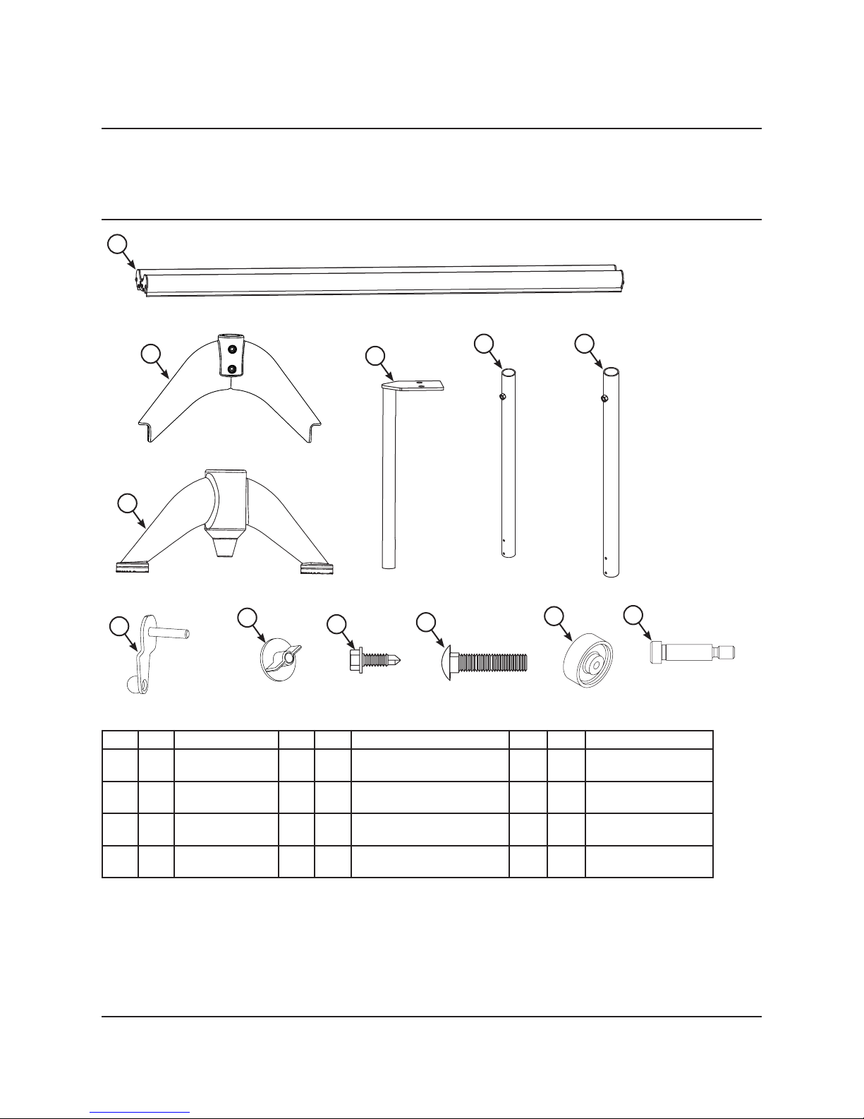
Parts List
1
2
3
7
Item Qty Description Item Qty Description Item Qty Description
8
4
9
10
5 6
11
12
1 1 Bridge 5 1 Short Outer Upright Tube 9 4 Self Tapping Screw,
1/4-20 x 3/4”
2 1 Large Base 6 1 Long Outer Upright Tube 10 4 Carriage Bolt,
3/8-16
3 1 Small Base
without Wheels
4 2 Inner Upright
Tube
7 2 Locking Lever 11 2 Poly Wheel,
2 x 5/16”
8 4 Plastic Wing Nut, 3/8-16 12 2
Shoulder Screw,
5/16 x 1”
3
Page 4

Assembly
1. Attach the Poly Wheels to the Large Base using two
5/16 x 1” Shoulder Screws and a 5/32” Allen Wrench.
2. Insert the Short Outer Upright Tube into the
Base Assembly.
Align the pilot holes in the Tube with the
clearance holes in the Base.
3. Insert the Long Outer Upright Tube into the
Base Without Wheels.
Align the pilot holes in the Tube with the clearance
holes in the Base.
4. Thread the 1/4-20 x 3/4” Self Tapping Screws
through the holes in the Bases and the rst
wall of the Upright Tubes.
Assembly
The Self Tapping Screws will cut threads
in the walls of the Upright Tubes as they
are tightened.
Continue to tighten each screw until it stops
against the Upright Tube.
Base
Large
Base
Short Outer
Upright Tube
1/4-20 x 3/4”
Self Tapping
Screws
Pilot
Holes
Poly
Wheels
5/16 x 1”
Shoulder
Screws
Long Outer
Upright Tube
Base
Without
Wheels
Note: Exceeding 66 in-lbs of tightening torque may damage the screw or tube threads.
4
Page 5

Assembly (continued)
5. Insert one Inner Upright Tube into the Outer Tube of each Base Assembly.
6. Lock the Inner Upright Tubes into position by threading a
Locking Lever into the hole located at the top of each
Outer Upright Tube and hand tightening.
Set the Inner Tubes at approximately the same position for
assembly purposes.
Note: If attaching the Power Strip Shelf Accessory, assemble it onto the bridge before completing
the next steps. Refer to “Power Strip Shelf”.
Inner Upright
Tubes
Locking
Levers
7. From the underside of the Bridge, slide the head of one 3/8-16 Carriage Bolt
into the channel at end of each of the two slots as shown.
Bridge
Hole count may vary depending
on length of Bridge.
3/8-16
Carriage Bolts
3/8-16
Carriage Bolts
5
Page 6

Assembly (continued)
8. Place the Mounting Bracket of each Base Assembly over the Carriage Bolts in the Bridge.
Be sure that each Carriage Bolt goes through the matching holes in the Mounting Brackets.
9. Thread a Plastic Nut onto each Carriage Bolt to secure the Base Assembly to the Bridge.
The plastic nut should be hand tightened only.
Plastic
Nuts
Plastic
Nuts
Mounting
Carriage
Bolts
Bracket
Mounting
Bracket
Carriage
Bolts
6
Page 7

Operation
To Set the Height
Two people are recommended, one to hold the Bridge in position and the other to loosen
and tighten the Locking Levers.
1. Loosen the Locking Levers on both of the Upright Posts and set the Bridge at the desired height.
2. Tighten the Locking Levers to secure in place.
To Set Upright Post Location
1. Loosen the Plastic Nuts that secure the Upright Post to the underside of the Bridge.
2. Slide the Upright Post assembly to the desired position along the attachment slots in the
Bridge extrusion.
3. Hand tighten the Plastic Nuts to secure in place.
Plastic
Nuts
Locking
Levers
!
CAUTION
The Bridge can drop suddenly
if the Locking Levers are not
securely tightened.
To Move the Flex TechBridge
1. Lift the end of the Bridge that does not have wheels and push or pull the TechBridge to the desired
location.
2. Remove any accessories that are not secured to the Bridge before moving.
Orienting Flex TechBridge to Flex Conductors Stand
1. Roll the Flex TechBridge up to the cast iron base of the Conductor’s Stand.
2. Drop the point of the smaller base on the Bridge (the base with no wheels) into the orientation
pockets of the Stand base.
3. The Bridge may be rotated to any angle along the oor to create an alcove work space
or parallel to the stand to create a straight working space.
Maintenance
1. Clean the Flex TechBridge with a mild detergent. Avoid using harsh or abrasive cleaning products.
2. Never apply oil or any lubricant to the height adjustment tube.
3. Periodically check fasteners to ensure that they have not loosened during use.
7
Page 8

Accessories (sold seperately)
Required Tools for Accessories
Work Surface Mount:
• Phillips Head Screwdriver
Keyboard Mounts:
• 9/16” Socket Wrench or Open End/Box End Wrench
• 7/32” Allen Wrench
Laptop Mount:
• Phillips Head Screwdriver
• 3/8” Socket Wrench or Open End/Box End Wrench
Cupholder:
• Phillips Head Screwdriver
• 3/8” Socket Wrench or Open End/Box End Wrench
Power Strip Shelf:
• No tools needed
Work Surface Mount
Keyboard Mounts
Universal Tablet Mount:
• Pliers
• 7/32” Allen Hex Socket Wrench (recommended)
or 7/32” Allen Wrench
Cupholder Power Strip Shelf
Laptop Mount
Universal Tablet Mount
8
 Loading...