

Page 1
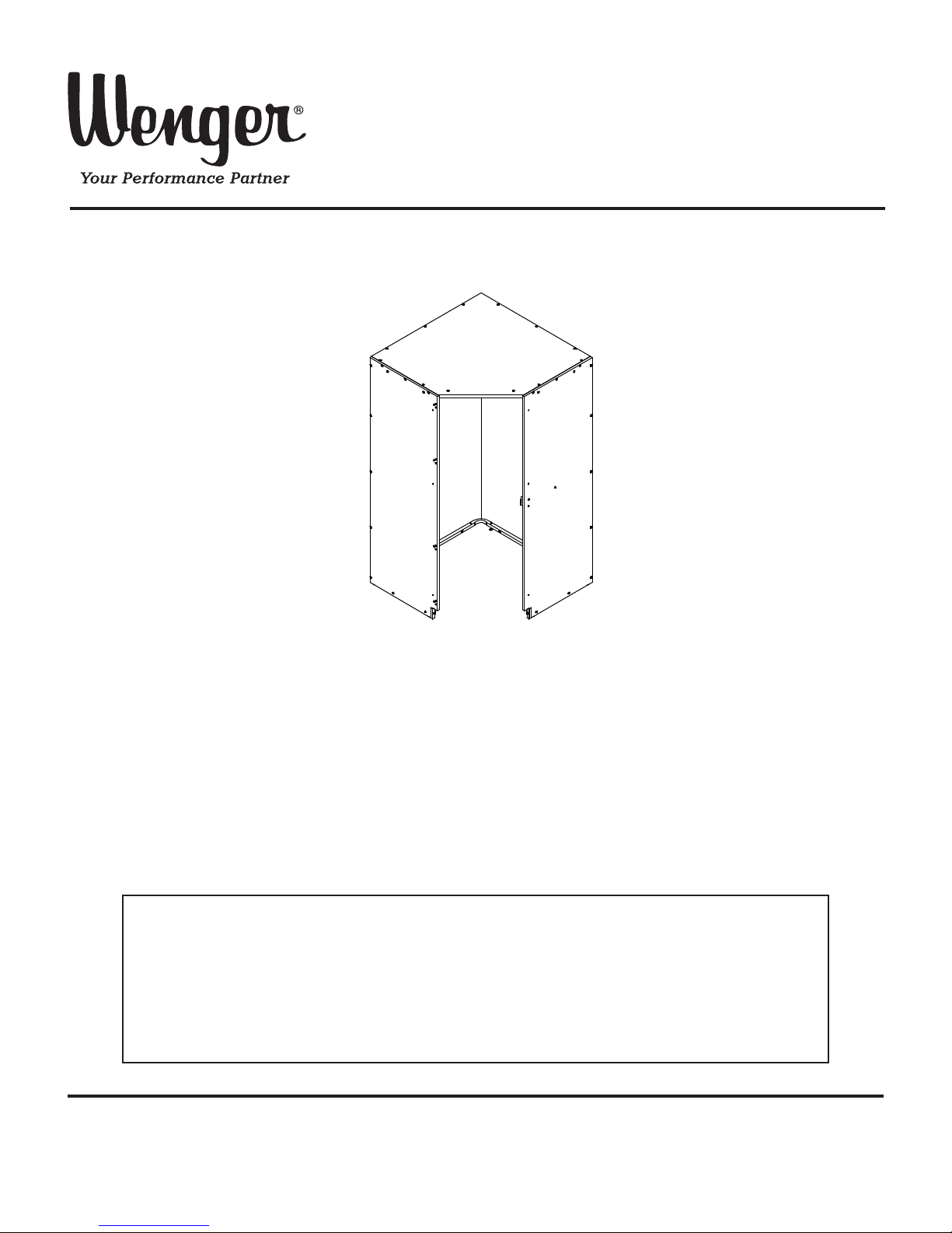
Assembly Instructions
Corner Cabinet and Options
Note: Please read and understand these instructions before assembling the parts.
Note: Assemble the Corner Cabinet in the room that it will be used in.
The assembled Corner Cabinet is typically too large to fit through a doorway.
Note: Assembly requires two people.
Note: Remove all items from the shipping cartons and arrange them in a convenient location.
Refer to the illustrations on the following pages.
If you need additional information, contact Wenger Corporation using the information below.
©Wenger Corporation 2014 Printed in USA 08/14 Part #250A893-05
Wenger Corporation, 555 Park Drive, P.O. Box 448, Owatonna, Minnesota 55060-0448
Questions? Call.....USA: 1-800-4WENGER (493-6437) • Worldwide: 1-507-455-4100 • www.wengercorp.com
CONTENTS
Safety . . . . . . . . . . . . . . . . . . . . . . . . . . . . . . . . . . . . . . . . . . . . . . . . . . . . . . . . . . . . . . . . . . .2
Important User Information . . . . . . . . . . . . . . . . . . . . . . . . . . . . . . . . . . . . . . . . . . . . . . . . . . .2
General . . . . . . . . . . . . . . . . . . . . . . . . . . . . . . . . . . . . . . . . . . . . . . . . . . . . . . . . . . . . . .2
Manufacturer . . . . . . . . . . . . . . . . . . . . . . . . . . . . . . . . . . . . . . . . . . . . . . . . . . . . . . . . . .2
Warranty . . . . . . . . . . . . . . . . . . . . . . . . . . . . . . . . . . . . . . . . . . . . . . . . . . . . . . . . . . . . .2
Corner Cabinet Assembly Instructions . . . . . . . . . . . . . . . . . . . . . . . . . . . . . . . . . . . . . . . . . .3
Shelf/Hanger Bar Option Assembly Instructions . . . . . . . . . . . . . . . . . . . . . . . . . . . . . . . . . .33
Revolving Shelf Option Assembly Instructions . . . . . . . . . . . . . . . . . . . . . . . . . . . . . . . . . . . .41
Page 2
GENERAL
Copyright© 2014 by Wenger Corporation
All rights reserved. No part of the contents of this manual may be reproduced, copied, or transmitted in
any form or by any means including graphic, electronic, or mechanical methods or photocopying,
recording, or information storage and retrieval systems without the written permission of the publisher,
unless it is for the purchaser's personal use.
Printed and bound in the United States of America.
The information in this manual is subject to change without notice and does not represent a commitment
on the part of Wenger Corporation. Wenger Corporation does not assume any responsibility for any
errors that may appear in this manual.
In no event will Wenger Corporation be liable for technical or editorial omissions made herein, nor for
direct, indirect, special, incidental, or consequential damages resulting from the use or defect of this
manual.
The information in this document is not intended to cover all possible conditions and situations that might
occur. The end user must exercise caution and common sense when assembling or installing Wenger
Corporation products. If any questions or problems arise, call Wenger Corporation at 1-800-887-7145.
MANUFACTURER
The Corner Cabinet is manufactured by:
Wenger Corporation
555 Park Drive
Owatonna, MN 55060
1-507-455-4100 • 1-800-733-0393
www.wengercorp.com
WARRANTY
This product is guaranteed free of defects in materials and workmanship for ten full years from
date of shipment. A full warranty statement is available upon request.
2
SAFETY
Throughout this manual you will find Cautions and Warnings which are defined as follows.
• Warning means that failure to follow the instruction may result in serious injury or death.
•Caution means that failure to follow the instruction may result in injury or damage to property.
Read and understand the following safety instructions before installing the Cover Panel.
GENERAL
INSTALLATION
Always observe and comply
with Warnings and Cautions
posted on the system
equipment.
Always wear safety glasses
when assembling the Corner
Cabinet.
Make sure that anyone who
helps assemble the Corner
Cabinet has read and
understands this manual.
!
CAUTION
Installation and use of the
Corner Cabinet must always
comply with the information
contained in this manual.
!
CAUTION
!
CAUTION
!
CAUTION
IMPORTANT USER INFORMATION
Page 3

3
Corner Cabinet Assembly Instructions
CONTENTS
Important User Information . . . . . . . . . . . . . . . . . . . . . . . . . . . . . . . . . . . . . . . . . . . . . . . . . . .4
Corner Cabinet Required Tools . . . . . . . . . . . . . . . . . . . . . . . . . . . . . . . . . . . . . . . . . . . . . . .4
Corner Cabinet Parts List . . . . . . . . . . . . . . . . . . . . . . . . . . . . . . . . . . . . . . . . . . . . . . . . . . . .4
Corner Cabinet Fasteners Parts List . . . . . . . . . . . . . . . . . . . . . . . . . . . . . . . . . . . . . . . . . . .4
Corner Cabinet Assembly . . . . . . . . . . . . . . . . . . . . . . . . . . . . . . . . . . . . . . . . . . . . . . . . . . . .5
Level the Cabinet . . . . . . . . . . . . . . . . . . . . . . . . . . . . . . . . . . . . . . . . . . . . . . . . . . . . . . . . . .21
Assemble Cabinet Connector Bracket . . . . . . . . . . . . . . . . . . . . . . . . . . . . . . . . . . . . . . . . . .22
Door Assembly Fasteners Parts List . . . . . . . . . . . . . . . . . . . . . . . . . . . . . . . . . . . . . . . . . . .23
Door Assembly Parts List . . . . . . . . . . . . . . . . . . . . . . . . . . . . . . . . . . . . . . . . . . . . . . . . . . . .23
Door Assembly Required Tools . . . . . . . . . . . . . . . . . . . . . . . . . . . . . . . . . . . . . . . . . . . . . . .23
Door Assembly . . . . . . . . . . . . . . . . . . . . . . . . . . . . . . . . . . . . . . . . . . . . . . . . . . . . . . . . . . .24
Wood Door Assembly . . . . . . . . . . . . . . . . . . . . . . . . . . . . . . . . . . . . . . . . . . . . . . . . . . .25
Grille Door Assembly . . . . . . . . . . . . . . . . . . . . . . . . . . . . . . . . . . . . . . . . . . . . . . . . . . .31
Page 4
4
IMPORTANT USER INFORMATION
INSTALLATION
• The Wenger Corner Cabinet installation must comply with local building regulations and codes.
• Personnel installing the Wenger Corner Cabinet must comply with the Warnings and Cautions in
the Safety Section.
INTENDED USE
• The Wenger Corner Cabinet is intended for indoor use in normal ambient temperature and humidity
conditions — it must not be exposed to prolonged outside weather conditions.
• The Wenger Corner Cabinet is intended to be permanently installed only as described in this manual.
CORNER CABINET REQUIRED TOOLS
• 6-foot Ladder
• Carpenters Level
• Tape Rule
• Carpenters Square
• Variable Speed Drill
• Mallet
• Philips Screwdriver
•
7
/8” Open End Wrench
• Hex Insert Bit
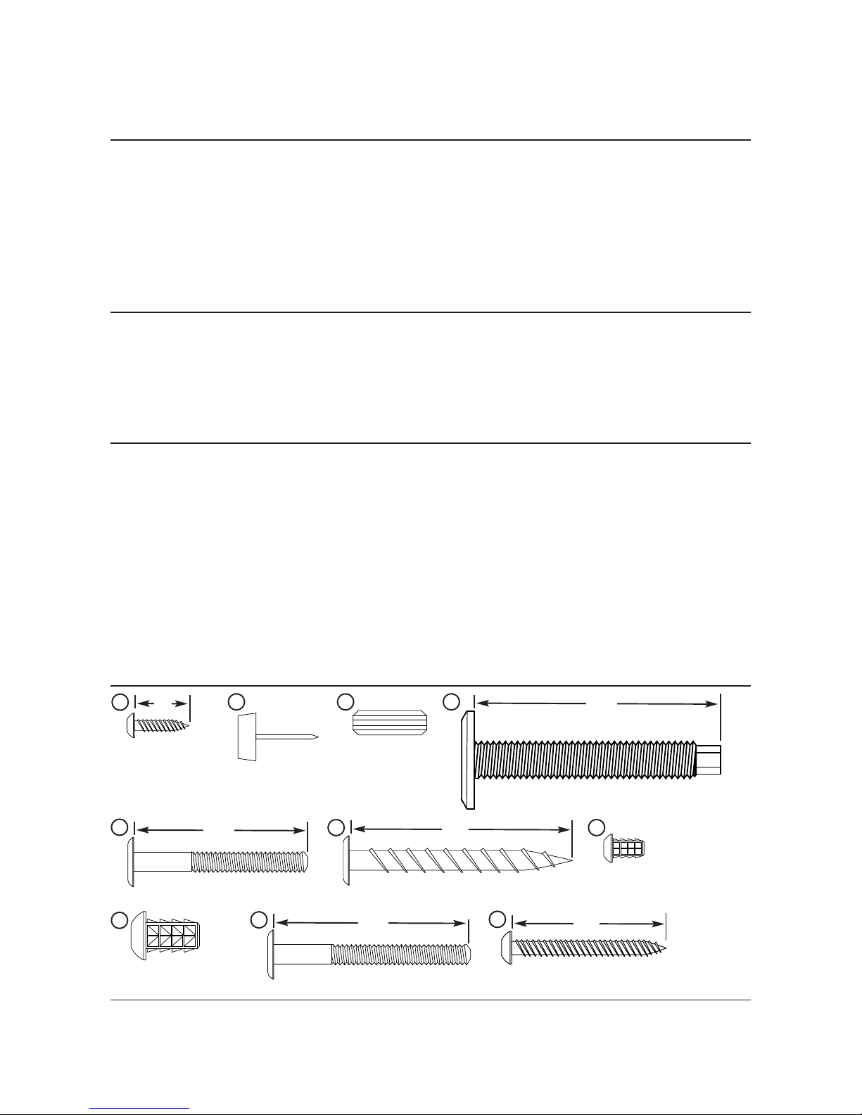
CORNER CABINET PARTS LIST
Item Description Part Number Item Description Part Number
1 Pan Head Screw X000045 12 Plastic Extrusion Trim Strip 145L460
2
Tube Plug, 11/8Square, 16 gauge
X001605 13
Hex Insert Bit, 5/32"
X001962
3 Tack Glide X001757 14 Bracket Connector, Cabinet 145A288
4 Wood Dowel X002540 15 Side Panel, RH, Corner Cabinet 250A145._
5
Leveler Glide, 3/8-16 x 21/2"
X002561 16 Side Panel, LH, Corner Cabinet 250A144._
6 Hex Socket Machine Screw 1.57" (40mm) 145L193 17 Back Panel, RH, Corner Cabinet 250A294._
7 Hex Socket Lag Screw 145R472 18 Back Panel, LH, Corner Cabinet 250A293._
8
Screw Insert, 8-32x7/16"
250A506._ 19 Top Panel, Corner Cabinet 250A214._
9 Screw Insert, 1/4-20 x 5/8" 146B507 20 Bottom Frame, Corner Cabinet 145R750
10 Hex Socket Machine Screw, 1.77" (45mm) 145L458 21 Upper Frame, Corner Cabinet 145R753
11
Pan Head Screw, oyster, 1-1/4" long
215B564 22 Filler Strips (one long, one short) 250A350._
23 Deflector Panel (use on Revolving Option) 250A284._
Screw Insert, 1/4-20 x 5/8”
Hex Socket Lag Screw
2”
7
Leveler Glide, 3/8-16 x 21/2”
21/2”
5
Pan Head Screw
5
/8”
1
Wood Dowel
4
9
Tack Glide
3
Pan Head Screw
11/4”
11
Hex Socket Machine Screw
1.77”
10
Screw Insert, 8-32 x 7/16”
(oyster)
8
Hex Socket Machine Screw
1.57”
6
FASTENERS PARTS LIST
The following tools must be supplied by the installer to install the Wenger Corner Cabinet:
Page 5
5
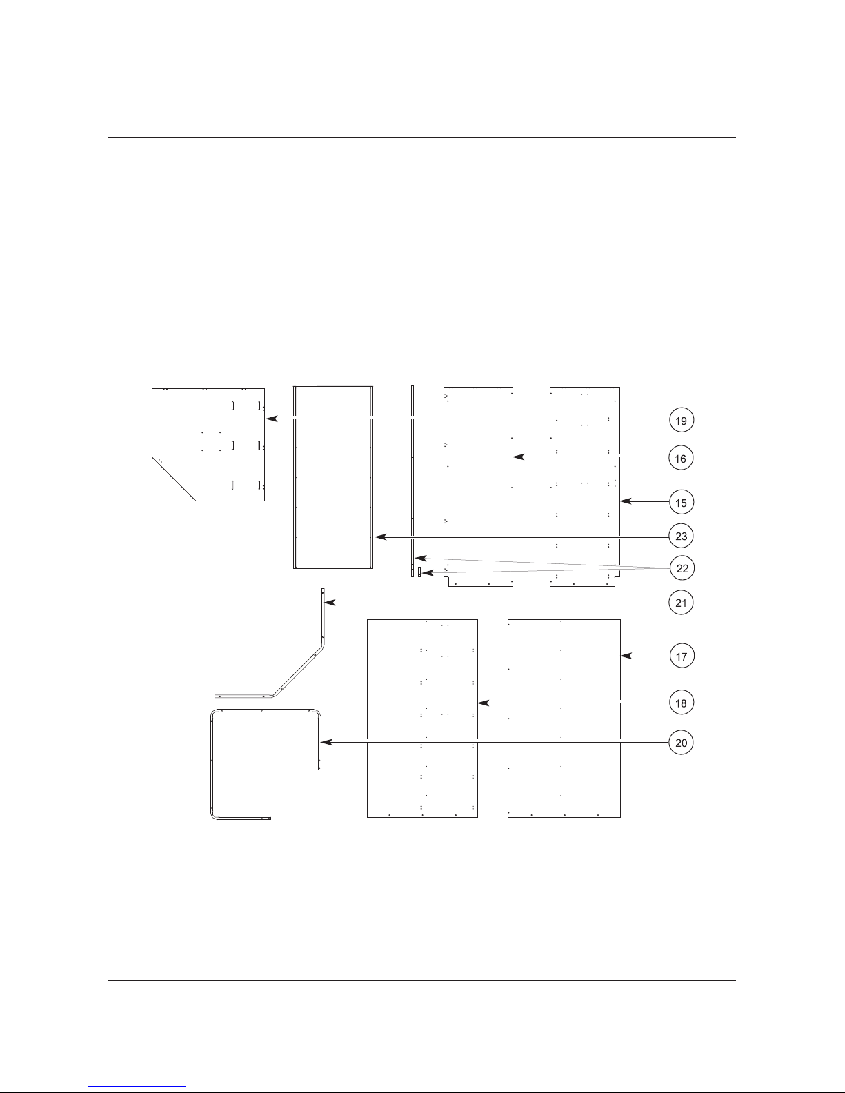
Before starting the Corner Cabinet assembly, do the
following.
1. Read and understand this assembly instruction.
2. Remove all items from the shipping carton and
arrange the parts as shown in the diagram below.
Make sure that all parts are present. Item
numbers refer to the Parts List on page 4 and the
table at the right.
3. Inventory the hardware package and make sure
that all required hardware is present. Discard any
items not used during the assembly.
Item Description
15 Right Hand Side Panel
16 Left Hand Side Panel
17 Right Hand Back Panel
18 Left Hand Back Panel
19 Top Panel
20 Bottom Frame
21 Upper Frame
22 Filler Strips
(one long/one short)
23 Deflector Panel*
* Use only with Revolving Options
CORNER CABINET ASSEMBLY
NOTE: Depending on Corner Cabinet configuration, hole positioning in the individual panels may vary.
Page 6
6
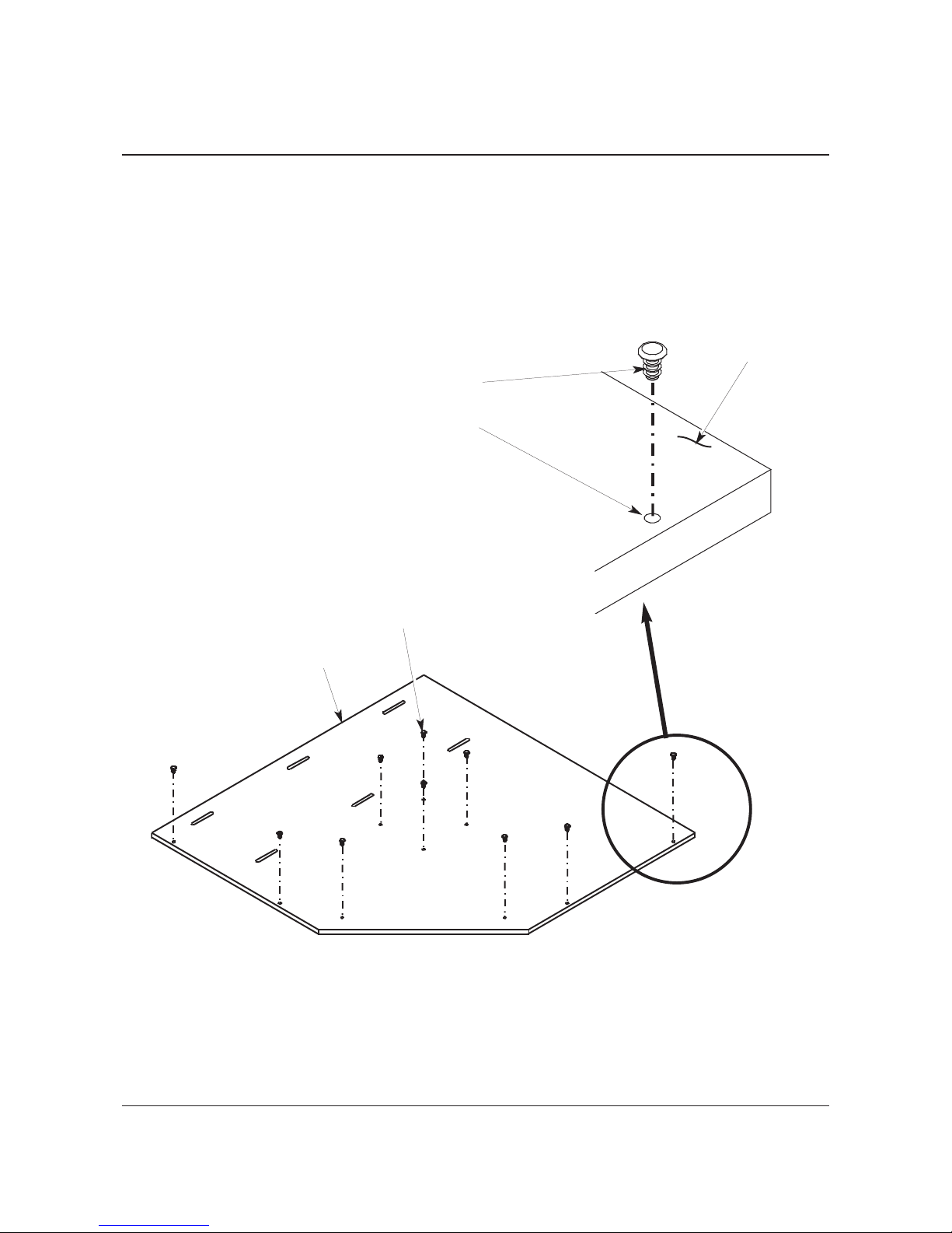
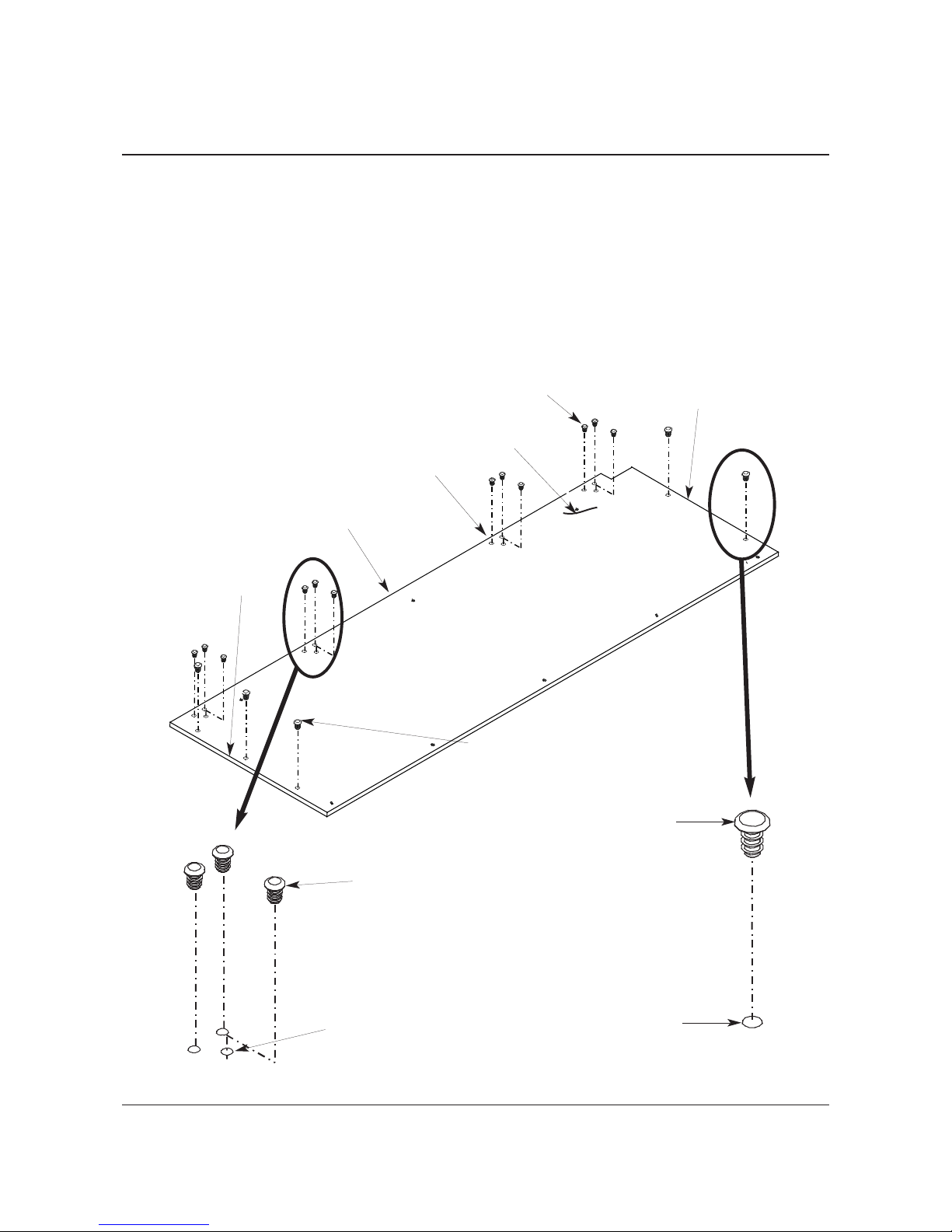
4. Place the Top Panel (19) flat on the floor with the inside surface facing downward (dowel holes do
not go through and are visible only on the inside surface).
IMPORTANT: Dowel holes should not be visible when inside surface is facing down.
5. Using a mallet, drive the Screw Inserts (9) into the clearance holes on the outside surface of the
Top Panel (19).
NOTE: Numerical notations that follow part names in this document refer to part list item numbers
on pages 4 and 5.
Top Panel (19)
Screw Insert, 1/4-20 x 5/8" (9)
Clearance Hole
Screw Insert, 1/4-20 x 5/8" (9)
(Install these only with Revolving Shelf Option)
Outside Surface
CORNER CABINET ASSEMBLY CONTINUED
NOTE: Depending on Corner Cabinet configuration, hole positioning in the individual panels may vary.
Page 7
7
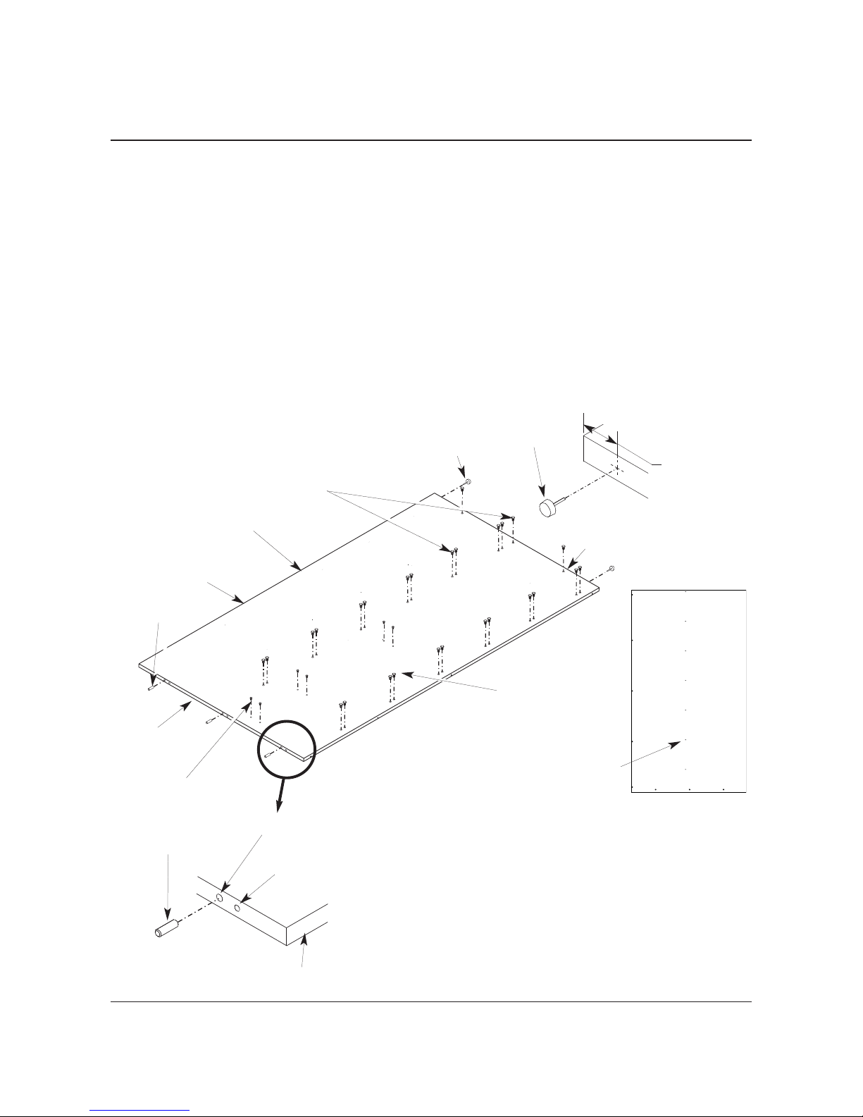
6. Place the Left Hand Back Panel (18) flat on the floor with the inside surface down.
IMPORTANT:
Shelf/Hanger Bar option - when the inside surface is facing down, the outside surface has most of
the clearance holes to the right and the 3 Dowel holes at the top of the panel are visible when
viewing it from the top edge (see the illustration below).
Rotating Shelf option - when the inside surface is facing down, the row of pilot holes at the center of
the panel will also be facing down (see the illustration below).
7. Using a mallet, drive 27 Screw Inserts (3 for the Rotating Shelf option) (9) into the 3/8” clearance
holes in the left Hand Back Panel (18) as shown below.
8. Using a mallet, drive 6 Screw Inserts (8) into the 1/4” clearance holes in the Left Hand Back Panel
(18) as shown below (Shelf/Hanger Bar option only).
9. Using the mallet, drive three Wood Dowels (4) into the three pilot holes on the top edge of the Panel.
10. Using the mallet, drive two Tack Glides (3) into the bottom surface of the Left Hand Back Panel (18)
as shown below. Each Tack Glide (3) should be about 11/2" from the corner.
NOTE: Depending on Corner Cabinet configuration, hole positioning in the individual panels may vary.
Screw Insert, 1/4-20 x 5/8" (9)
Left Hand Back Panel (18)
Bottom Surface of Panel
Left Hand Edge of Panel
Outside surface
Wood Dowel (4)
5
/16" Pilot Hole
Pilot Hole for Lag
Screw (to be inserted
at a later step
Wood Dowel (4)
Screw Insert, 8-32 x 7/16" (8)
Right Hand
Edge of Panel
Top Edge of
Panel
Tack Glide (3)
Drive Glide into
bottom surface
about 1” to 11/2"
from corner edge
Tack
Glide (3)
CORNER CABINET ASSEMBLY CONTINUED
Row of
Pilot Holes
Inside Surface of Left
Hand Back Panel
Page 8
8
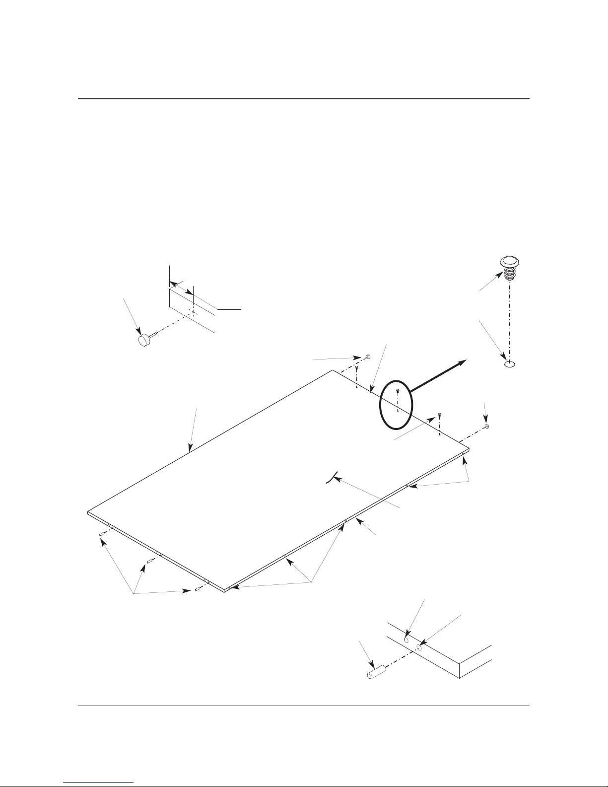
11. Place the Right Hand Back Panel (17) flat on the floor with the inside surface facing down.
IMPORTANT:
When the Right Hand Back Panel has the inside surface facing down, there are five pilot holes on
the right hand edge and the three Dowel holes at the top of the panel are visible when viewing it
from the top edge (refer to the illustration below).
12. Using the mallet, drive three Screw Inserts (9) into the three 3/8” diameter pilot holes at the bottom of
the Panel.
13. Drive three Wood Dowels (4) into the three 5/16” diameter pilot holes on the top edge of the Panel.
Refer to the illustration below.
14. Using the mallet, drive two Tack Glides (3) into the bottom surface of the Right Hand Back Panel
(17) about 11/2” from each bottom corner as shown below.
Right Hand Back Panel (17)
3
/8" Pilot Hole
Bottom Edge of Panel
Left Hand Edge
of Panel
Outside Surface
Wood
Dowel (4)
5
/16" Pilot Hole
3
/16" Pilot Hole for Lag
Screw (to be inserted
at a later step
Wood Dowel (4)
Pilot
Holes
Screw Insert, 1/4-20 x 5/8" (9)
Screw Insert, 1/4-20 x 5/8" (9)
Tack Glide (3)
Drive Glide into bottom surface
about 1” to 11/2" from corner
edge
Tack Glide (3)
Tack Glide (3)
CORNER CABINET ASSEMBLY CONTINUED
Pilot Holes
Page 9
9
15. Place the Right Hand Side Panel (15) flat on the floor with the inside surface down and outside
surface facing upward.
IMPORTANT:
When the inside surface is facing down, the dowel holes on the inside surface will not be visible
(see the illustration below).
16. Using a mallet, drive the Screw Inserts (9) into the
3
/8” clearance holes in the left Right Hand Side
Panel (15) as shown below (Shelf/Hanger Bar option shown).
17. Using a mallet, drive the Screw Inserts (8) into the 1/4” clearance holes in the Right Hand Side Panel
(15) as shown below (Shelf/Hanger Bar option shown).
NOTE: Depending on Corner Cabinet configuration, hole positioning in the individual panels may vary.
Screw Insert, 8-32 x 7/16" (8)
Screw Insert, 1/4-20 x 5/8" (9)
Right Hand Side Panel (15)
Top Edge of Panel
Left Hand Edge of Panel
Bottom Edge of Panel
Outside Surface
CORNER CABINET ASSEMBLY CONTINUED
Page 10

10
18. Turn the Right Hand Side Panel (15) over so that the outside surface is facing down (dowel holes
will now be visible).
19. Using a mallet, drive three Wood Dowels (4) into the three 5/
1
6
” diameter pilot holes close to the top
edge of the Right Hand Side Panel (15).
NOTE: The dowel holes do not go all the way through and are on the inside surface of the Side Panel.
20. Using the mallet, drive two Tack Glides (3) into the bottom surface of the Right Hand Side Panel
(15) about 11/2” from each bottom corner as shown below.
NOTE: Depending on Corner Cabinet configuration, hole positioning in the individual panels may vary.
Right Hand Side Panel (15) with
inside surface facing up
Wood Dowel (4)
Top Edge
Top Edge
Wood Dowel (4)
5
/16" Clearance Hole
7
/16" Deep
3
/16" Pilot Hole through
Inside Surface
Bottom Edge
Drive Glide into bottom surface
about 1” to 11/2" from corner
edge
Tack Glide (3)
Tack Glide (3)
CORNER CABINET ASSEMBLY CONTINUED
Page 11
11
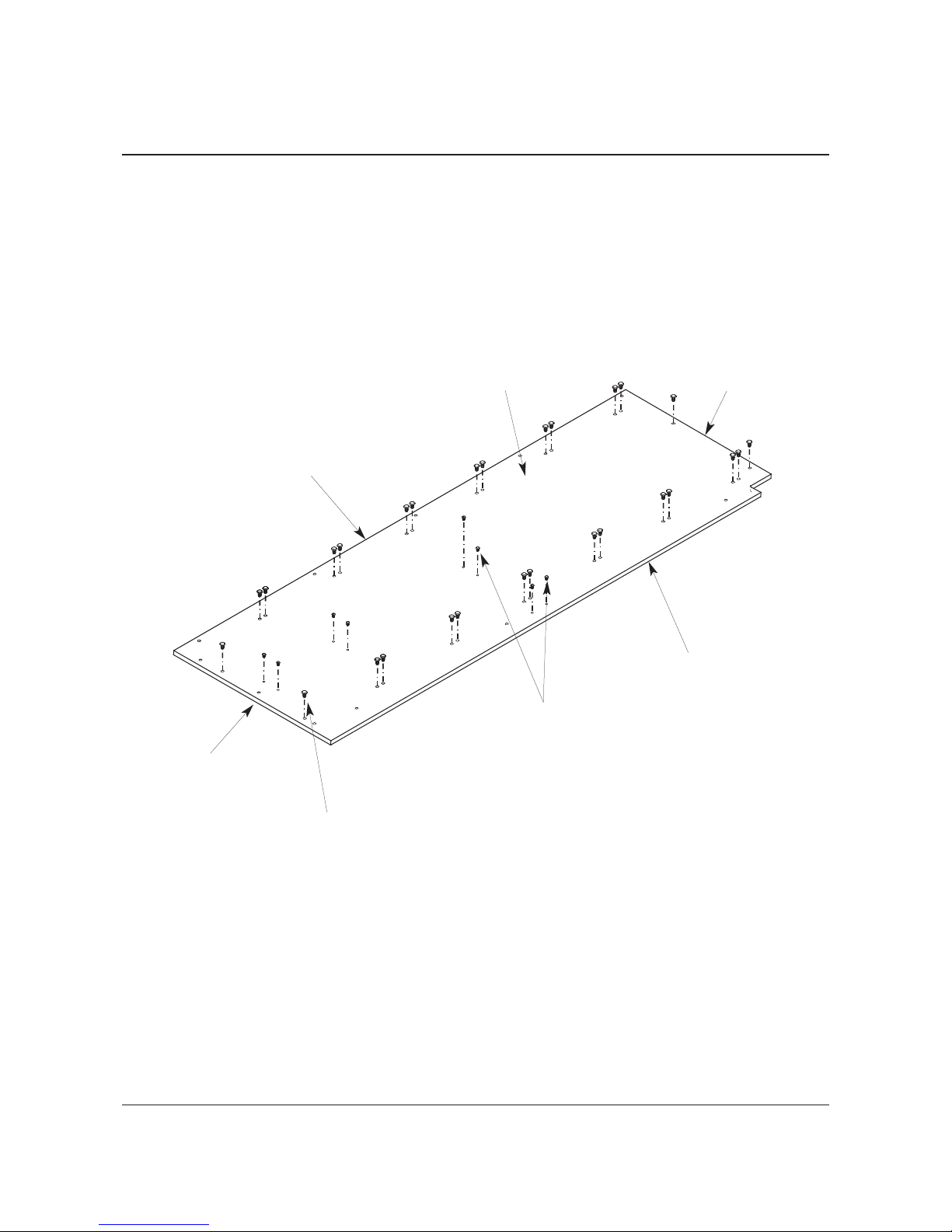
21. Place the Left Hand Side Panel (16) flat on the floor with the inside surface down and outside
surface facing upward
IMPORTANT:
When the inside surface is facing down, the dowel holes on the inside surface will not be visible
(see the illustration below).
22. Using a mallet, drive four Screw Inserts (9) into the
3
/8” clearance holes in the Left Hand Side Panel
(16) as shown below.
23. Using a mallet, drive twelve Screw Inserts (8) into the 1/4” clearance holes in the Left Hand Side
Panel (16) as shown below.
NOTE: Depending on Corner Cabinet configuration, hole positioning in the individual panels may vary.
Screw Insert, 1/4-20 x 5/8" (9)
3
/8" Clearance Hole
Left Hand Side Panel (16)
Top Edge of Panel
Left Hand Edge of Panel
Bottom Edge of Panel
Outside Surface
Screw Insert, 1/4-20 x 5/8" (9)
Screw Insert, 8-32 x 7/16" (8)
1
/4" Clearance Hole
Screw Insert, 8-32 x 7/16" (8)
CORNER CABINET ASSEMBLY CONTINUED
Page 12

12
24. Turn the Left Hand Side Panel (16) over so that the outside surface is facing down. (dowel holes will
now be visible).
25 . Using a mallet, drive three Wood Dowels (4) into the three 5/16” diameter pilot holes close to the top
edge of the Left Hand Side Panel (16).
NOTE: The dowel holes do not go all the way through and are on the inside surface of the Side Panel.
26. Using the mallet, drive two Tack Glides (3) into the bottom surface of the Left Hand Side Panel (16)
about 11/2” from each bottom corner as shown below.
NOTE: Depending on Corner Cabinet configuration, hole positioning in the individual panels may vary.
Left Hand Side Panel (16) with inside
surface facing up
Wood Dowel (4)
Top Edge
Top Edge
Wood Dowel (4)
5
/16" Pilot Hole
7
/16" Deep
3
/16" Clearance
Through-Hole
Inside Surface
Bottom Edge
Drive Glide into bottom surface
about 1” to 11/2" from corner
edge
Tack Glide (3)
CORNER CABINET ASSEMBLY CONTINUED
Page 13
13
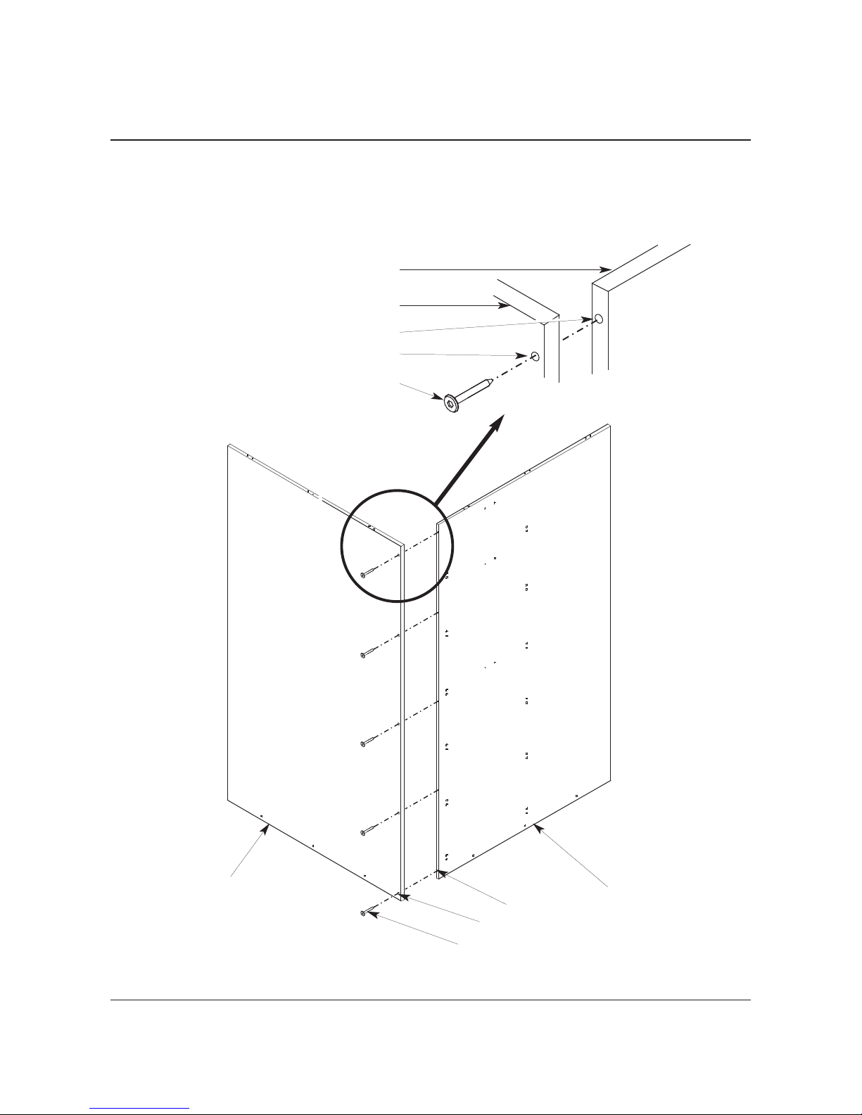
27. With two people working together, place the Right Hand Back Panel (17) and the Left Hand Back
Panel (18) vertical as shown below.
28. Using the Hex Insert Bit (13), connect the two Back Panels together with five Hex Lag Screws (7).
Pilot holes locate the position of the Hex Lag Screws.
Right Hand Back Panel (17)
Left Hand Back Panel (18)
Hex Lag Screw (7)
Pilot Holes
Right Hand Back Panel (17)
Left Hand Back Panel (18)
Hex Lag Screw (7)
Pilot Hole
Clearance Hole
Clearance Hole
CORNER CABINET ASSEMBLY CONTINUED
NOTE: Depending on Corner Cabinet configuration, hole positioning in the individual panels may vary.
Page 14
14
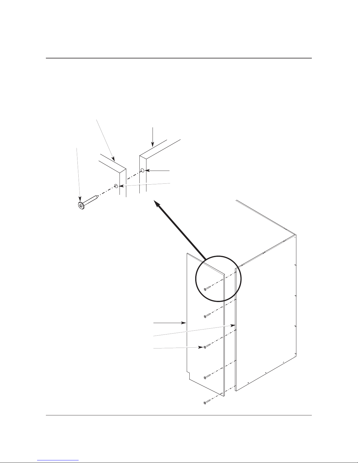
29. With two people working together, attach the Right Hand Side Panel (15) to the two assembled Back
Panels, keeping the panels vertical as shown below.
30. Using the Hex Insert Bit (13), connect the Right Hand Side Panel (15) to the Right Hand Back Panel
(17) with five Hex Lag Screws (7). Pilot holes locate the position of the Hex Lag Screws.
NOTE: Do not tighten the Lag Screws. Allow the head of each Lag Screw to extend 1/2” from the surface
of the Side Panel.
Right Hand Back Panel (17)
Right Hand Side Panel (15)
Hex Lag Screw (7)
Pilot Hole
Right Hand Back Panel (17)
Right Hand Side Panel (15)
Hex Lag Screw (7)
Clearance Hole
CORNER CABINET ASSEMBLY CONTINUED
Page 15
15
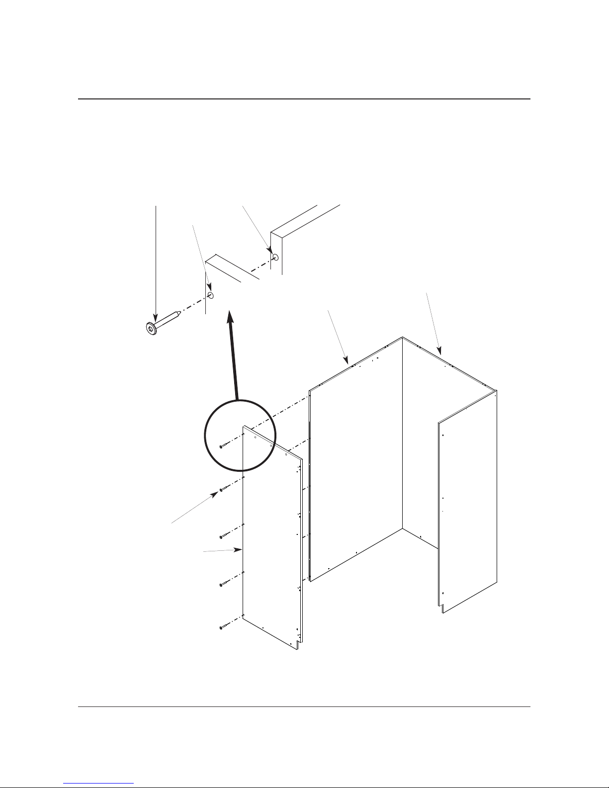
31. With two people working together, attach the Left Hand Side Panel (16) to the two assembled Back
Panels keeping them vertical as shown below.
32. Using the Hex Insert Bit (13), attach the Left Hand Side Panel (16) to the Left Hand Back Panel (18)
with five Hex Lag Screws (10). Pilot holes locate the position of the Hex Lag Screws.
NOTE: Do not tighten the Lag Screws. Allow the head of each Lag Screw to extend 1/2” from the
surface of the Side Panel.
Hex Lag Screw (7)
Left Hand Side Panel (16)
Hex Lag Screw (7) Pilot Hole
Left Hand Back Panel (18)
Clearance Hole
Right Hand Back Panel (17)
CORNER CABINET ASSEMBLY CONTINUED
Page 16
16
33. Make sure that the Hex Lag Screws (7) holding the two Side Panels to the two Back Panels are
loosened.
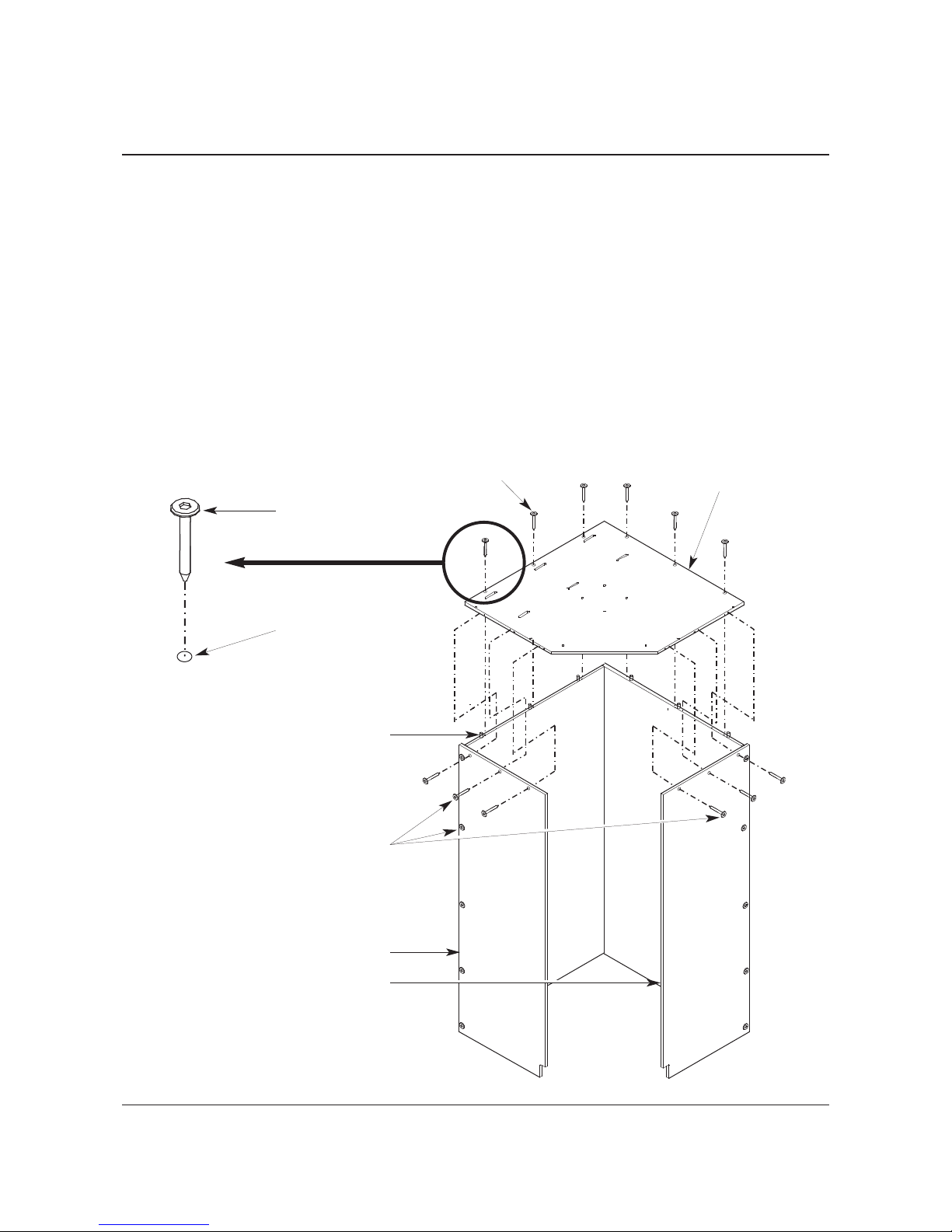
34. Carefully place the Top Panel (19) onto the Back Panels aligning the Wood Dowels (4) in the two
Back Panels to the dowel pilot holes on the inside surface of the Top Panel.
35. Make sure that the Wood Dowels (4) in the two Side Panels align to the dowel pilot holes in the Top
Panel and, using the Hex Insert Bit (13), tighten the 10 Hex Lag Screws (7) that fasten the Side
Panels to the Back Panels.
36. Using the Hex Insert Bit (13), fasten:
a. Six Hex Lag Screws (7) through the clearance holes in the Top Panel (19) into the two Back
Panels.
b. Three Hex Lag Screws (7) through the clearance holes in the Left Hand Side Panel (16) into the
pilot holes in the Top Panel.
c. Three Hex Lag Screws (7) through the clearance holes in the Right Hand Side Panel (17) into
the pilot holes in the Top Panel.
Top Panel (19)
Hex Lag Screw, 2" long (7)
Left Hand Side Panel (16)
Right Hand Side Panel (17)
Wood Dowel (4)
Hex Lag Screw, 2" long (7)
Hex Lag Screw, 2" long (7)
3
/8" Clearance Hole
CORNER CABINET ASSEMBLY CONTINUED
Page 17

17
37. Attach a Trim Strip (12) to the Left Hand Side Panel (16) and the Right Hand Side Panel (15) using
a Pan Head Screw, 11/4” long (11) for each Trim Strip as shown in the illustration below.
Pan Head Screw,
painted, 1
1
/4" long (11)
Trim Strip (12)
Trim Strip (12)
Right Hand Side Panel (15)
Left Hand Side Panel (16)
CORNER CABINET ASSEMBLY CONTINUED
Page 18

18
38. Install the Upper Frame (21) inside the upper part of the Corner Cabinet by doing the following.
a. Hold the Upper Frame in position as shown below.
b. Using the Hex Insert Bit (13), fasten the Upper Frame to the Top Panel (19) with six Hex Socket
Machine Screws (10).
c. Using the Hex Insert Bit (13), fasten the Upper Frame to the Left Hand Side Panel(16) with two
Hex Socket Machine Screws (10).
d. Using the Hex Insert Bit (13), fasten the Upper Frame to the Right Hand Side Panel(17) with two
Hex Socket Machine Screws (10).
Top Panel (19)
Left Hand Side
Panel (16)
Right Hand Side
Panel (17)
Upper Frame (21)
Hex Socket Machine Screw,
1.77" (45 mm) long (10)
Hex Socket Machine Screw,
1.77" (45 mm) long (10)
The Top Panel, Right Hand Side
Panel, and Left Hand Side Panels are
shown disassembled for clarity only.
CORNER CABINET ASSEMBLY CONTINUED
Page 19

19
39. Fasten five Leveler Glides (5) to the Bottom Frame (20) using a 7/8" open end wrench as shown
below. Screw the Leveler Glide into the Bottom Frame until the head of the Leveler Glide is against
the Bottom Frame Weld Nut. Do not tighten.
NOTE: The Weld Nut is on the bottom surface of the Bottom Frame (20) as shown in the illustration
below.
40. Using the mallet, drive a Tube Plug (2) into each open end of the Bottom Frame (20).
Bottom Frame (20)
Leveler Glide, 3/8-16 x 21/2" (5)
Leveler Glide, 3/8-16 x 21/2" (5)
Bottom Frame (20)
Leveler Glide,
3
/8-16 x 21/2" (5)
Leveler Glide,
3
/8-16 x 21/2" (5)
Bottom Frame (20)
Weld Nut
Tube Plug (2)
Tube Plug (2)
The Weld Nut must be
on the bottom of the
Bottom Frame when the
Leveler Glide is
attached.
CORNER CABINET ASSEMBLY CONTINUED
Page 20

20
41. Install the Bottom Frame (20) inside the lower part of the Corner Cabinet by doing the following.
a. Hold the Bottom Frame (20) in position as shown below.
b. Using the Hex Insert Bit (13), fasten the Bottom Frame to the Right Hand Back Panel (17) and
Left Hand Back Panel (18) with six Hex Socket Machine Screws (10) as shown below.
c. Using the Hex Insert Bit (13), fasten the Bottom Frame to the Left Hand Side Panel(16) with two
Hex Socket Machine Screws (10).
d. Using the Hex Insert Bit (13), fasten the Bottom Frame to the Right Hand Side Panel(15) with
two Hex Socket Machine Screws (10).
Left Hand Side
Panel (16)
Right Hand Side
Panel (15)
Hex Socket Machine Screw,
1.77" (45 mm) long (10)
The Right Hand Side Panel and Left
Hand Side Panels are shown
disassembled for clarity only.
Hex Socket Machine Screw,
1.77" (45 mm) long (10)
Bottom Frame (20)Left Hand Back Panel (18)
Right Hand Back Panel (17)
CORNER CABINET ASSEMBLY CONTINUED
Page 21

21
1. Check the level of the entire floor where the Corner Cabinet will be installed. Determine the highest
point of the floor in that area. Extend all Leveler Glides until the bottom of the cabinet is higher than
the highest point in the floor (so that the bottom of cabinet is not touching the floor).
2. Adjust the Leveler Glides at points 2 and 3 (adjustments to 5 may be necessary) until the edges X
and Y of the cabinet are plumb and parallel.
3. Measure A and B with a measuring tape and adjust the Leveler Glides 1 and 2 until A is equal to B
(±1/32”). Adjustments to 3 and 4 may be necessary.
4. Adjust Leveler Glides at points 1 and 2 (adjustments to 5 may be necessary) until the edges Z and
W of the cabinet are plumb (front-to-back).
5. Re-measure A and B with a measuring tape and make sure that A is still equal to B (±1/32”).
Readjust if necessary (steps 2 to 4).
A B
1
2
3
4
5
X
Z
Y
W
!
CAUTION
DO NOT try to level
the cabinet to
match soffits.
!
CAUTION
DO NOT try to
plumb the cabinet
to match adjacent
walls.
!
CAUTION
For proper door
alignment, follow
these instructions
carefully.
NOTE: Filler Strips (22) are used when attaching the Corner Cabinet to other Wenger storage
cabinets. Refer to the Storage Cabinet Installation Instruction Manual for information about
fastening cabinets together.
LEVEL THE CABINET
Page 22

22
1. Place the Corner Cabinet in its final position against a wall or surface that will serve as an anchor
for the cabinet.
2. Using the Cabinet Connector Bracket (19) as a template, mark the position for the four holes to
mount the bracket.
3. Drill pilot holes for the four (1) Pan Head Screws, 5/8” long, with a 1/8” drill bit.
4. Attach the Cabinet Connector Bracket (19) to the Corner Cabinet Top Panel using four (1) Pan Head
Screws, 5/8” long.
5. Connect the Bracket to the wall with the appropriate fasteners.
NOTE: Numerical notations that follow part names in this document refer to part list item numbers
on pages 22 and 23.
!
CAUTION
The Corner Cabinet can be
unsafe unless it is fastened
to a wall as described in
this procedure.
Use a method to fasten the
bracket to the wall that is
appropriate for the wall
surface.
Pan Head Screw, 5/8" long (1)
Cabinet Connector Bracket (19)
ASSEMBLE CABINET CONNECTOR BRACKET
Page 23

23
Item Description Part Number Item Description Part Number
1 Pan Head Screw X000045 10 Handle, Full Wood Door 250A502._
2 Hex Nut with Lock washer X001762 11 Latch Assembly, Full Wood Door 250A501._
3 Truss Head Screw X001767 12 Hinge, Wood Door 250A505._
4 Pan Head Screw, painted 250A511._ 13 Door Catch, Full Length 145R475
5 Flat Head Screw, painted 250A509._ 14 Door Stop, Corner Cabinet 250A535._
6
Screw Insert, 8-32 x 7/16"
250A506._ 15
Hex Insert Bit, 5/32"
X001962
7 Flat Head Screw, painted 250A507._ 16 Door, Full 27" Wood 250A332._
8 Hex Cap Insert Nut 250A510._ Door, Full 27" Grille 250A302._
9 Door Stop, Cabinet 145L098 19 Cabinet Connector Bracket 145A288
DOOR ASSEMBLY PARTS LIST
DOOR ASSEMBLY REQUIRED TOOLS
• Variable Speed Drill
• 6-foot Ladder
• Mallet
• Philips Screwdriver
• Hex Insert Bit
Pan Head Screw
5
/8”
1
Screw Insert, 8-32 x 7/16”
(oyster)
6
DOOR ASSEMBLY FASTENERS PARTS LIST
The following tools must be supplied by the installer to install the doors:
Hex Cap Insert Nut
8
5
3
/4”
Flat Head Screw (painted)
Pan Head Screw
5
/8”
7
Pan Head Screw
3
/4”
4
Lock Washer
Hex Nut
2
Truss Head Screw
3
/4”
3
Page 24

24
Before starting the Door assembly, do the following.
1. Read and understand this assembly instruction.
2. Remove all items from the shipping carton and arrange the parts as shown in the diagram below.
Make sure that all parts are present. Item numbers refer to the Part List on page 22 and the table
below.
3. Inventory the hardware package and make sure that everything required is present. Discard any
items not used during the assembly.
IMPORTANT: The following “Door Assembly” procedures are for a left side hinge. For a right side
hinge, the images would be mirrored.
NOTE: Make sure that the
cabinet is level before
assembling the door.
Item Description
9 Door Stop Cabinet
10 Handle, Wood Full Door
11 Latch Assembly, Full Wood Door
12 Hinge Wood Door
Item Description
13 Door Catch Full Length
14 Door Stop, Corner Cabinet
16 Door, Full
19 Cabinet Bracket
DOOR ASSEMBLY
Page 25

25
WOOD DOOR ASSEMBLY
1. Assemble the Screw Inserts (6) to the Wood Door (16) as follows.
a. Place the Wood Door (16) on the floor with the outside surface facing upward.
b. Using a mallet, drive eight Screw Inserts (6) into the eight clearance holes in the Door as shown
below.
NOTE: Reference Holes (do not go through) are between the hinge clearance holes on the inside
surface. Refer to the illustration at the bottom of this page.
Wood Door (16)
Screw Insert, 8-32 x 7/16" (6)
Outside Surface
Clearance Hole
Wood Door (16)
Clearance Hole
Bottom Edge
Reference Hole
Inside Surface
Pilot Hole
DOOR ASSEMBLY CONTINUED
Page 26

26
WOOD DOOR ASSEMBLY CO
NTINUED
2. Assemble the Wood Door Hinges (12) to the Wood Door as follows.
a. Lay the Wood Door flat with the inside surface facing upward (heads of the Screw Inserts,
installed in step 1, are on the outside surface and must face downward).
b. Align the four Wood Door Hinges (12) to the clearance holes in the Wood Door and, using a
phillips head screwdriver fasten the HInges to the Screw Inserts in the Door using eight Flat
Head Screws (5) (matches hinge color).
c. Fasten one Flat Head Screw (7) (Matches hinge color) to each Hinge using a phillips head
screwdriver.
Wood Door (16)
Inside Surface
Flat Head Screw,
3
/4" long (5)
Flat Head Screw,
5
/8" long (7)
Wood Door
Hinge (12)
Flat Head Screw,
5
/8" long (7)
Wood Door
Hinge (12)
DOOR ASSEMBLY CONTINUED
Page 27

27
3. Assemble the Wood Door Latch Assembly (11) and Wood Door Handle (10) to the Wood Door (16)
as follows.
a. Insert the two Wood Door Latch Assembly Threaded Post (11) into the two clearance holes on
the outside surface of the Door as shown below.
b. Insert two Hex Cap Insert Nuts (8) into the two clearance holes and tighten the Nuts to the
Threaded Posts using a Hex Insert Bit (15).
c. Insert the two Wood Door Handle Threaded Post (10) into the two clearance holes as shown
below.
d. Insert two Hex Cap Insert Nuts (8) into the two clearance holes and tighten the Nuts to the
Wood Door Handle Threaded Posts using a Hex Insert Bit (15).
NOTE: All door hardware should match hinge color.
Hex Cap Insert Nut (8)
Wood Door (16)
Wood Door
Handle (10)
Wood Door Latch
Assembly (11)
Clearance Hole
Inside Surface of
Wood Door
Wood Door Handle
Threaded Post
Latch Assembly
Threaded Post
DOOR ASSEMBLY CONTINUED
WOOD DOOR ASSEMBLY CO
NTINUED
Page 28

28
4. Install the Door Catch (13) to the inside (lower) surface of the Top Panel by inserting two Pan
Head Screws (1) through the clearance holes in the Catch and into the two Pilot Holes in the inside
surface of the Top Panel. Use a phillips head screw driver to tighten the Screws. See the illustration
below.
Door Catch (13)
Pan Head Screw, 5/8" long (1)
Top Panel
DOOR ASSEMBLY CONTINUED
WOOD DOOR ASSEMBLY CO
NTINUED
Page 29

29
5. Assemble the Door Stop to the Right Hand Side Panel as follows.
a. Assemble the Cabinet Door Stop (9) to the Corner Cabinet Door Stop (14) with two Lock
Washer Hex Nuts (2) and two Truss Head Screws (3) (Corner Cabinet Door Stop color matches
Hinge color).
NOTE: Make sure that the wide lip of the Cabinet Door Stop (9) is oriented as shown below
(wide lip facing the Corner Cabinet Door Stop and the narrow lip facing away from the Corner
Cabinet Door Stop).
b. Attach the Door Stop Assembly to the inside surface of the Right Hand Side Panel with two
Painted Pan Head Screws (4) using a phillips head screwdriver.
Right Hand Side
Panel
Hex Nut with Lock
Washer (2)
Corner Cabinet
Door Stop (14)
Cabinet Door
Stop (9)
Truss Head Screw,
3
/4" long (3)
Pan Head Screw,
3
/4" long (4)
Clearance Holes (Screw
Inserts on outside surface
Wide Lip
Narrow Lip
a
b
DOOR ASSEMBLY CONTINUED
WOOD DOOR ASSEMBLY CO
NTINUED
Page 30

30
6. Attach the Wood Door (16) to the Corner Cabinet as follows.
a. Align the Wood Door to the Corner Cabinet so that the mounting holes in each Wood Door
Hinge (12) align to the clearance holes in the Left Hand Side Panel with screw inserts.
b. Using a phillips head screwdriver, attach the upper hinge of the door to the Left Hand Side
Panel by using three Painted Flat Head Screws (5) as shown below.
A screw may be inserted into the rear-most hole of the cabinet and the door may be hung from it
by placing the slotted hole in the hinge onto the screw and moving the hinge forward until the other
two screw inserts are exposed. Tighten the three screws in each hinge.
c. Attach the lower hinges in the same manner.
NOTE: All door hardware should match hinge color.
Wood Door (16)
Top Panel
Right Hand Side Panel
Clearance Hole
Flat Head Screw, Painted,
3
/4" long (5)
Wood Door Hinge (12)
DOOR ASSEMBLY CONTINUED
WOOD DOOR ASSEMBLY CO
NTINUED
Page 31

31
1. Assemble the Grille Door Stop as follows.
a. Attach the Cabinet Door Stop (9) to the Corner Cabinet Door Stop (14) with two Lock Washer
Hex Nuts (2) and two Truss Head Screws (3) (Corner Cabinet Door Stop color matches Hinge
color).
NOTE: Make sure that the narrow lip of the Cabinet Door Stop (9) is oriented as shown below (narrow
lip facing the Corner Cabinet Door Stop and the wide lip facing away from the Corner Cabinet
Door Stop).
b. Attach the Door Stop Assembly to the inside surface of the Right Hand Side Panel with two
Painted Pan Head Screws (4) using a phillips head screwdriver.
Right Hand Side
Panel
Hex Nut with Lock
washer (2)
Corner Cabinet
Door Stop (14)
Cabinet Door
Stop (9)
Truss Head Screw,
3/4" long (3)
Pan Head Screw,
3/4" long (4)
Right Hand Side
Panel
Clearance Holes (Screw
Inserts on outside surface)
Narrow Lip
Wide Lip
a
b
DOOR ASSEMBLY CONTINUED
GRILLE DOOR ASSEMBLY
Page 32

32
2. Attach the Grille Door (16) to the Corner Cabinet as follows.
a. Align the Grille Door (16) to the Corner Cabinet so that the mounting holes in each Grille Door
Hinge aligns to the clearance holes in the Left Hand Side Panel with screw inserts.
b. Using a phillips screwdriver, attach the upper Hinge of the door to the Left Hand Side Panel by
using three Painted Flat Head Screws (5) as shown below.
A screw may be inserted into the rear-most hole of the cabinet and the door may be hung from it
by placing the slotted hole in the hinge onto the screw and moving the hinge forward until the other
two screw inserts are exposed. Tighten the three screws in each hinge.
c. Attach the lower hinges in the same manner.
Grille Door (16)
Top Panel
Right Hand Side Panel
Clearance Hole
Flat Head Screw, Painted,
3/4” long (5)
Grille Door Hinge
DOOR ASSEMBLY CONTINUED
GRILLE DOOR ASSEMBLY CONTINUED
Page 33

33
Shelf/Hanger Bar Option Assembly Instructions
Corner Cabinet with a Fixed Shelf Corner Cabinet with Hanger Bars
CONTENTS
Important User Information . . . . . . . . . . . . . . . . . . . . . . . . . . . . . . . . . . . . . . . . . . . . . . . . . . .34
Shelf/Hanger Bar Required Tools . . . . . . . . . . . . . . . . . . . . . . . . . . . . . . . . . . . . . . . . . . . . . .34
Shelf/Hanger Bar Parts List . . . . . . . . . . . . . . . . . . . . . . . . . . . . . . . . . . . . . . . . . . . . . . . . . .34
Shelf/Hanger Bar Fasteners Parts List . . . . . . . . . . . . . . . . . . . . . . . . . . . . . . . . . . . . . . . . . .34
Shelf/Hanger Bar Assembly . . . . . . . . . . . . . . . . . . . . . . . . . . . . . . . . . . . . . . . . . . . . . . . . . .35
Brass Clothes Hook Assembly . . . . . . . . . . . . . . . . . . . . . . . . . . . . . . . . . . . . . . . . . . . .35
Fixed Shelf Assembly . . . . . . . . . . . . . . . . . . . . . . . . . . . . . . . . . . . . . . . . . . . . . . . . . . .36
Band Uniform Hanger Bar Assembly . . . . . . . . . . . . . . . . . . . . . . . . . . . . . . . . . . . . . . .38
Choral Robe Hanger Assembly . . . . . . . . . . . . . . . . . . . . . . . . . . . . . . . . . . . . . . . . . . .39
Page 34

34
Item Description Part Number Item Description Part Number
1
Truss Head Screw, 3/4"
X001767 5 Brass Clothes Hook, Pair X002585
2
Hex Insert Bit, 5/32"
X001962 6 Shelf, 30" x 48", oyster 145R439
3
Pan Head Screw, 13/4"
X001969 7 Shelf Support, 48", oyster 145R899
4
Hex Socket Button Head Screw, 5/8"
145L441 8 Hanger Bar, 48", oyster 145A328
9 Velcro Strip 145R492
IMPORTANT USER INFORMATION
INSTALLATION
• The Wenger Corner Cabinet Shelf/Hanger Bar installation must comply with local building
regulations and codes.
• Personnel installing the Wenger Corner Cabinet Shelf/Hanger Bar must comply with the Warnings
and Cautions in the Safety Section.
INTENDED USE
• The Wenger Corner Cabinet Shelf/Hanger Bar is intended for indoor use in normal ambient
temperature and humidity conditions — it must not be exposed to prolonged outside weather
conditions.
• The Wenger Corner Cabinet Shelf/Hanger Bar is intended to be permanently installed only as
described in this manual.
SHELF/HANGER BAR REQUIRED TOOLS
• Variable Speed Drill
• Philips Screwdriver
SHELF/HANGER BAR PARTS LIST
SHELF/HANGER BAR FASTENERS PARTS LIST
The following tools must be supplied by the installer to install the Wenger Corner Cabinet Shelf/Hanger
bar:
Pan Head Screw
13/4”
3
Hex Socket Button Head Screw
5
/8”
4
Truss Head Screw
3
/4”
1
Page 35

Before starting the Shelf/Hanger Bar assembly, do the following.
1. Read and understand this assembly instruction.
2. Remove all items from the shipping carton and make sure that all parts are present. Item numbers
refer to the Part List above and the table below.
3. Inventory the hardware package and make sure that all required hardware is present. Discard any
items not used during the assembly.
Item Description
5 Brass Clothes Hook/Screws
6 Shelf
7 Shelf Support
8 Hanger Bar
35
1. Install four Brass Clothes Hooks (5) as follows.
a. Fasten each Brass Clothes Hook (5) to the inside surface of the Left Hand Side Panel with two
Brass Clothes Hook Screws.
b. Pilot holes, 1/8" diameter, on the inside surface of the Left Hand Side Panel locate the Clothes
Hooks.
SHELF/HANGER BAR ASSEMBLY
BRASS CLOTHES HOOK ASSEMBLY
Left Hand Back PanelLeft Hand Side Panel
Brass Clothes Hook (5)
Brass Clothes Hook (5)
Brass Clothes Hook
Screws (5)
1
/8" Pilot Holes
1
/8" Pilot Holes
NOTE: Numerical notations
that follow part names
in this document refer
to part list item
numbers on this page.
Page 36

36
SHELF/HANGER ASSEMBLY CONTINUED
To install a Shelf, do as follows.
1. Align one of the Shelf Supports (7) to the 3/8" diameter clearance holes on the inside surface
of the Left Hand Back Panel next to the Right Hand Side Panel as shown below.
Orient the Tabs to face away from the Back Panel.
2. Using the Hex Insert Bit, fasten the Support Bar with four Hex Socket Button Head Screws (4).
The screws fasten to a screw insert.
3. Repeat steps 1 and 2 for the remaining Shelf Support (7). Make sure that the Shelf Support
Tabs are oriented as shown below.
Left Hand Back Panel
3
/8" Clearance Hole
Right Hand Back Panel
Shelf Support Tab facing away
from the Right Hand Back
Panel
Shelf Support Tab facing
toward the Right Hand
Back Panel
3
/8" Clearance Hole
Shelf Support Tab
Hex Socket Button Head
Screw, 5/8" (4)
Shelf Support (7)
Shelf Support (7)
Shelf Support (7)
Hex Socket Button Head
Screw, 5/8" (4)
FIXED SHELF ASSEMBLY
Page 37

37
SHELF/HANGER ASSEMBLY CONTINUED
Shelf (6)
4. To install an upper Shelf (6), do as follows.
a. Place the Shelf (6) on the Shelf Supports (7).
b. Align the three clearance holes in the front Shelf Support (7) with the three pilot holes on the
front bottom side of the Shelf (6).
c. Attach the Shelf (6) to the front Shelf Support (7) with three Pan Head Screws (3) as shown
below.
NOTE: Tighten the screws snugly, but do not over tighten (use care with power screwdrivers).
d. Align the clearance holes in the rear Self Support with the pilot holes on the rear bottom side of
the Shelf and attach with two Pan Head Screws (3).
Clearance Hole
Pan Head
Screw, 1
3
/4" (3)
Front Shelf Support (7)
Pilot holes on
bottom of Shelf
Rear Shelf Support (7)
5. To install a bottom Shelf (6), do as follows.
a. Apply five Velcro Strips (9) to the front and rear Shelf Supports (7) as shown below.
b. Remove the paper backing from the five Velcro Strips (9).
c. Place the Shelf (6) onto the Velcro Strips (9) and Shelf Supports (7) and against the cabinet
back panel. The Shelf can be removed if the cabinet needs additional leveling.
Shelf Support (7)
Shelf (6)
Velcro Strip (9)
Pan Head Screw, 13/4" (3)
Velcro Strip (9)
Front Edge
FIXED SHELF ASSEMBLY CONTINUED
Page 38

38
SHELF/HANGER ASSEMBLY CONTINUED
To install the Hanger Bars (8) for Uniform Storage, do as follows.
1. Align the clearance holes in the end of a Hanger Bars (8) to the upper pair of 1/4" diameter clearance
holes in the Left Hand Back Panel and the Right Hand Side Panel.
2. Using a phillips head screwdriver, fasten the Hanger Bar to the Left Hand Back Panel and the Right
Hand Side Panel with four Truss Head Screws (1). The screws fasten to a screw insert.
3. Repeat steps 1 and 2 for the second Hanger Bar (8) using the lowest set of 1/4" diameter clearance
holes (these are about 38" below the upper set of holes) as shown below.
1
/4" Clearance Holes
Truss Head Screw, 3/4" (1)
Hanger Bar (8)
Right Hand Side Panel
Left Hand Back Panel
Hanger Bar (8)
1
/4" Clearance Holes
BAND UNIFORM HANGER BAR ASSEMBLY
Page 39

39
SHELF/HANGER ASSEMBLY CONTINUED
Truss Head Screw, 3/4" (1)
Hanger Bar (8)
1
/4" Clearance Holes
Right Hand Side Panel
Left Hand Back Panel
Hanger Bar (8)
1
/4" Clearance Holes
To install the Hanger Bar (8) for Choral Robes, do as follows.
1. Align the clearance holes in the end of a Hanger Bar (8) to the mid-pair of 1/4" diameter clearance
holes (13" below the upper set of holes) in the Left Hand Back Panel and the Right Hand Side
Panel.
2. Using a phillips head screwdriver, fasten the Hanger Bar to the Left Hand Back Panel and the Right
Hand Side Panel with four Truss Head Screws (1). The screws fasten to a screw insert.
3. Discard the second Hanger Bar (8).
CHORAL ROBE HANGER ASSEMBLY
Page 40

40
This page is intentionally blank.
Page 41

41
Revolving Shelf Option Assembly Instructions
Corner Cabinet Revolving Shelf Option
shown with six Half Shelf Assemblies
Corner Cabinet Flag Storage Option shown
with four Flag/Robe Assemblies and two
Half Shelf Assemblies
CONTENTS
Important User Information . . . . . . . . . . . . . . . . . . . . . . . . . . . . . . . . . . . . . . . . . . . . . . . . . . .42
Revolving Shelf Required Tools . . . . . . . . . . . . . . . . . . . . . . . . . . . . . . . . . . . . . . . . . . . . . . .42
Revolving Shelf Parts List . . . . . . . . . . . . . . . . . . . . . . . . . . . . . . . . . . . . . . . . . . . . . . . . . . . .42
Revolving Shelf Fasteners Parts List . . . . . . . . . . . . . . . . . . . . . . . . . . . . . . . . . . . . . . . . . . .42
Revolving Shelf Assembly . . . . . . . . . . . . . . . . . . . . . . . . . . . . . . . . . . . . . . . . . . . . . . . . . . .42
Assemble Deflector Panel to the Corner Panel . . . . . . . . . . . . . . . . . . . . . . . . . . . . . . .44
Assemble Base Frame and Center Column . . . . . . . . . . . . . . . . . . . . . . . . . . . . . . . . . .45
Assemble a Half Shelf to the Center Column . . . . . . . . . . . . . . . . . . . . . . . . . . . . . . . .48
Assemble a Flag/Choral Robe Pack . . . . . . . . . . . . . . . . . . . . . . . . . . . . . . . . . . . . . . .49
Page 42

42
Item Description Part Number Item Description Part Number
1
Capscrew, 1/4-20 x 3/4" long
X000047 8 Deflector Panel 250A284._
2
Flat Washer, 3/8" ID
X000410 9 Top Plate Assembly 145R838
3
Capscrew, 3/8-16 x 13/4" long
X001552 10 Base Frame Assembly 145R839
4
Capscrew, 3/8-16 x 31/4" long
X001560 11 Center Column Assembly 145R840
5
Locknut, 3/8-16
X001848 12 Half Shelf Assembly 145R860
6
Thrust Washer, 11/64ID
X002666 13 Flag/Choral Robe Bar Assembly 145R861
7
Truss Head Screw, 5/8" long, oyster
146B509 14 Leveler Glide X002820
IMPORTANT USER INFORMATION
INSTALLATION
• The Wenger Corner Cabinet Revolving Shelf installation must comply with local building regulations
and codes.
• Personnel installing the Wenger Corner Cabinet Revolving Shelf must comply with the Warnings and
Cautions in the Safety Section.
INTENDED USE
• The Wenger Corner Cabinet Revolving Shelf is intended for indoor use in normal ambient temperature
and humidity conditions — it must not be exposed to prolonged outside weather conditions.
• The Wenger Corner Cabinet Revolving Shelf is intended to be permanently installed only as described
in this manual.
REVOLVING SHELF REQUIRED TOOLS
• Philips Screwdriver
• Adjustable Wrench
•
9
/16” Socket and Ratchet
(7/16” and 1/2” sockets are optional)
•
7
/16”, 1/2” and 9/16” Open End Wrenches
REVOLVING SHELF PARTS LIST
Locknut
5
Leveler Glide
31/4”
4
Capscrew 1/4-20 x 3/4"
3
/4”
1
Capscrew 3/8-20 x 13/4"
3
Flat Washer 3/8” ID
2
Thrust Washer 11/64” ID
6
REVOLVING SHELF FASTENERS PARTS LIST
The following tools must be supplied by the installer to install the Wenger Corner Cabinet Revolving Shelf:
3”
14
Truss Head Screw
5
/8”
7
13/4”
Capscrew 3/8-20 x 31/4"
Page 43

43
Before starting assembly of the Corner Cabinet Revolving Options, do the following.
1. Read and understand this assembly instruction.
2. Remove all items from the shipping carton and arrange the parts as shown in the diagram below.
Make sure that all parts are present. Item numbers refer to the Part List on page 42 and the table
below.
3. Inventory the hardware package and make sure that all required hardware is present. Discard any
items not used during the assembly.
Item Description
8 Deflector Panel
9 Top Plate Assembly
10 Base Frame Assembly
11 Center Column Assembly
12 Half Shelf Assembly
13 Flag/Choral Robe Assembly
REVOLVING SHELF ASSEMBLY
Page 44

44
To assemble the Deflector Panel (8) to the Corner Cabinet, do as follows.
1. Place the Deflector Panel (8) against the Right Hand Back Panel and the Left Hand Back Panel.
2. Align the 14 Clearance Holes in the Deflector Panel (8) to the seven Pilot Holes in the Right Hand
Back Panel and the seven Pilot Holes in the Left Hand Back Panel.
3. Insert a Truss Head Screw (7) into the upper left Clearance Hole and, using a phillips head
screwdriver, screw it into the upper Pilot Hole in the Left Hand Back Panel.
4. Repeat step 3, fastening a Truss Head Screw (7) to the upper right Pilot Hole on the Right Hand
Back Panel.
5. Continue attaching the Deflector Panel with the other 12 Truss Head Screws.
NOTE: Numerical notations that follow part names in this document refer to part list item numbers
on pages 42 and 43.
Truss Head Screw, 5/8" long (7)
Right Hand Back Panel
Upper Left Clearance Hole
Deflector Panel (8)
Pilot Hole
Right Hand Back Panel
Left Hand Back Panel
Deflector Panel (8)
Truss Head Screw, 5/8" long (7)
REVOLVING SHELF ASSEMBLY CONTINUED
ASSEMBLE DEFLECTOR PANEL TO THE CORNER PANEL
Page 45

45
1. Assemble the Leveler Glides (14) to the Base Frame Assembly (10) as follows.
a. Screw four Leveler Glides (14) into the lower surface of the four 3/8-16 threaded holes in the
Base Frame Assembly (10).
b. Use a 1/2" wrench, if necessary, and screw the Leveler Glides into the Base Frame until the head
of each Leveler Glide is nearly against the lower surface as shown below.
Threaded Hole, 3/8-16
Leveler Glide, 3" long (14)
Threaded Hole, 3/8-16
Leveler Glide,
3" long (14)
Bass Frame Assembly (10)
Turn the Leveler Glide (14) into the
threaded hole until it is nearly flush
with the lower surface of the Base
Frame Assembly (10)
Lower Surface
Upper Surface
Head
REVOLVING SHELF ASSEMBLY CONTINUED
ASSEMBLE BASE FRAME AND CENTER COLUMN
Page 46

46
2. Assemble the Base Frame Assembly (10), Center Column (11), and Top Plate Assembly (9)
as follows.
a. Place the Base Frame Assembly (10) flat on the floor.
b. Place the Thrust Washer (6) onto the Base Frame Assembly Post (10).
c. Place the Center Column Assembly (11) onto the Base Frame Assembly Post and Thrust
Washer (6).
NOTE: One person should hold the Center Column Assembly (11) in an upright position until
completing step 3 on the next page.
d. Insert the the Top Plate Assembly Post (9) into the Clearance
Hole at the top of the Center Column Assembly.
Top Plate Assembly (9)
Bass Frame Assembly (10)
Thrust Washer (6)
Center Column Assembly (11)
Bass Frame Assembly Post
Top Plate Assembly Post (facing downward)
Center Column Assembly Clearance Hole
REVOLVING SHELF ASSEMBLY CONTINUED
ASSEMBLE BASE FRAME AND CENTER COLUMN CO
NTINUED
Page 47

47
3. Fasten the Center Column Assembly components to the Corner Cabinet as follows.
a. With two people working together, slide the Base Frame, Center Column and Top Plate
(assembled together) through the doorway into the Corner Cabinet. It may be necessary to
rotate the Base Frame Assembly as it is pushed through the doorway.
NOTE: The Center Column Assembly can be placed inside the Corner Cabinet without
removing any panels (such as the Top Panel or side panels).
b. Rotate the Base Frame Assembly (10) so that the two short legs face the back panels (see
illustration below) and the wings rest on top of the Base Frame.
c. Align the four Clearance Holes in the Base Frame Assembly Wings (10) to the four
3
/8" diameter
clearance holes in the Bottom Frame.
d. Insert four Capscrews (3) into the clearance holes on the Base Frame Assembly (10) and, using
a 9/16" wrench or socket and ratchet, screw the Capscrews (3) into the Bottom Frame.
e. Turn the Top Plate Assembly (9) so that the four Clearance Holes in the corners align with the
four holes on the inside surface of the Top Panel (these holes have Screw Inserts on the outside
surface).
f. Insert four Capscrews (1) into the four Top Plate Assembly (9) Clearance Holes and, using a 7/16"
wrench or socket and ratchet, screw the Capscrews (1) into the four Top Panel Screw Inserts.
Top Panel
(shown cut away)
Screw Insert
Center Column Assembly (11)
Top Plate Assembly (9)
Capscrew, 3/8-16 x 13/4" (3)
Clearance Hole
Capscrew,
1
/4-20 x 3/4" long (1)
Top Panel
Bottom Frame
Bottom Frame
Clearance Hole
Base Frame Assembly (10)
3
/8" Clearance Hole
Base Frame
Assembly (10)
Shorter Legs
Base Frame Assembly (10) Wing
REVOLVING SHELF ASSEMBLY CONTINUED
ASSEMBLE BASE FRAME AND CENTER COLUMN CO
NTINUED
Page 48

48
To install the Half Shelf Assembly to the Center Column Assembly, do as follows.
1. Place the Half Shelf Assembly (12) against the Center Column Assembly (11), aligning the
Clearance Holes in the Half Shelf with the Clearance Holes in the Center Column.
2. Insert a Capscrew (4) through a Flat Washer (2) and then through the upper Clearance Hole in the
Half Shelf, until the capscrew threaded end extends from the Center Column.
3. If a second Half Shelf Assembly (12) is to be assembled, align the upper clearance hole to the
threaded end of the Capscrew (4) and push the Shelf against the Center Column.
4. Place a Flat Washer (2) onto the threaded end of the Capscrew (4).
5. Screw a Locknut (5) onto the Capscrew (4).
6. Repeat steps 2, 4, and 5 at the lower clearance hole.
7. Using two 9/16" wrenches or sockets and ratchets, tighten the Capscrews and Locknuts.
8. Install additional Half Shelf Assemblies by repeating steps 1 to 7.
Half Shelf Assembly (12)
Capscrew, 3/8-16 x 31/4" long (4)
Locknut, 3/8-16 (5)
Flat Washer (2)
!
CAUTION
Make sure all
weight on shelves
is evenly
distributed.
!
CAUTION
Do not place more
than 50 pounds on
a Half Shelf
Assembly.
Clearance Holes
Center Column Assembly (11)
Locknut, 3/8-16 (5)
REVOLVING SHELF ASSEMBLY CONTINUED
ASSEMBLE A HALF SHELF TO THE CENTER COLUMN
Page 49

49
1. Assemble two Flag/Choral Robe Assemblies (13) to the Center Column (11) as follows. Refer to
page 51 for the placement of the Flag/ Choral Robe Assemblies.
NOTE: If you are assembling a Flag Storage Option, install the Flag/Choral Robe Assemblies (13)
five feet above the Revolving Shelf (12). Refer to the illustration for step 3.
a. Hold a Flag/Choral Robe Assembly (13) against the Center Column Assembly (11) aligning the
Upper Clearance Hole to the clearance hole in the Center Column Assembly.
b. Insert a Capscrew (4) through a Flat Washer (5) and then through the upper Clearance Hole in
the Flag/Choral Robe Assembly, until the threaded end extends from the the Center Column
Assembly.
c. Align the Upper Clearance Hole in a second Flag/Choral Robe Assembly (13) to the threaded
end of the Capscrew (4) and push the Shelf against the Center Column.
d. Place a Flat Washer (2) onto the Capscrew (4).
e. Screw a Locknut (5) onto the Capscrew (4).
f. Repeat steps b to e using the third clearance hole from the top (shown in the illustration below).
g. Using two 9/16" wrenches, tighten the Capscrews and Locknuts.
Capscrew, 3/8-16 x 31/4" long (4)
Flat Washer (2)
Upper Clearance Hole
Third Clearance Hole from the Top
Flat Washer (2)
Flag/Choral Robe Assembly (13)
Center Column
Assembly (11)
Locknut, 3/8-16 (5)
REVOLVING SHELF ASSEMBLY CONTINUED
ASSEMBLE A FLAG/CHORAL ROBE PACK
Page 50

50
2. To assemble the second pair of Flag/Choral Robe Assemblies (13), do as follows.
a. Place a Flag/Choral Robe Assembly (13) against the Center Column Assembly (11) between the
two assembled Flag/Choral Robe Assemblies with the upper edge even with the other
assemblies(refer to the illustration below).
b. Insert a Capscrew (4) through a Flat Washer (5) and then through the second from the top
Clearance Hole in the Flag/Choral Robe Assembly, pushing the Capscrew (4) until the threaded
end extends from the Center Column Assembly.
c. Align the second from the top Clearance Hole in the fourth Flag/Choral Robe Assembly (13) to
the Capscrew (4) and push the Flag/Choral Robe Assembly (13) against the Center Column.
d. Place a Flat Washer (2) onto the Capscrew (4).
e. Screw a Locknut (5) onto the Capscrew (4).
f. Repeat steps b to e using the lowest clearance hole (shown in the illustration below).
g. Using two 9/16" wrenches or sockets and ratchets, tighten the Capscrews and Locknuts.
Flag/Choral Robe Assembly (13)
Capscrew, 3/8-16 x 31/4" long (4)
Lowest Clearance Hole
Second Clearance Hole from the Top
Flat Washer (2)
Center Column
Assembly (11)
Make sure these edges are
at the same level
Complete Flag/Choral Robe
Assembly Option
Locknut, 3/8-16 (5)
REVOLVING SHELF ASSEMBLY CONTINUED
ASSEMBLE FLAG/CHORAL ROBE PACK (C
ONTINUED
)
Page 51

51
Flag Storage Option — Place the
Flag/Choral Robe Assemblies five feet
higher than the upper surface of the Half
Shelf Assemblies
5-feet
Flag/Choral Robe
Assembly (13)
Center Column
Assembly (11)
Half Shelf
Assemblies (12)
3. If you are assembling a Flag Storage Option, locate the Flag/Choral Robe Assembly (13) five feet
above the Half Shelf Assemblies (12) and place a Pad on the upper surface of each Half Shelf
Assembly (12) as shown below.
Pad
4. If you are assembling a Revolving Garment Option with two Flag/Choral Robe Packs, locate the
Flag/Choral Robe Assemblies (13) about at the top and at the mid point on the Center Column
Assembly and the Half Shelf Assemblies (12) at the bottom as shown below. Place a Pad on the
upper surface of each Half Shelf Assembly (12)
Pad
Flag/Choral Robe
Assembly (13)
approximately at the top
Center Column Assembly (11)
Half Shelf
Assemblies (12)
Revolving Garment Option — Place the
Flag/Choral Robe Assemblies at the
mid-point and at the top of the Center
Column and the Half Shelf Assemblies at
the bottom as shown above.
Flag/Choral Robe
Assembly (13)
approximately at the
mid-point
Half Shelf
Assemblies (12)
REVOLVING SHELF ASSEMBLY CONTINUED
ASSEMBLE FLAG/CHORAL ROBE PACK (C
ONTINUED
)
Page 52

52
This page is intentionally blank.
 Loading...