

Wenger Audio System 501, Audio System 502 Owner's Manual

Owner ’s Manual
Audio System Series 500
©Wenger Corporation 2005 Printed in USA 01/05 Part Number 126B929-3
Wenger Corporation, 555 Park Drive, P.O. Box 448, Owatonna, Minnesota 55060-0448
Questions? Call.....USA: (800) 733-0393 • International (call collect): (507) 455-4100 • www.wengercorp.com
CONTENTS
Safety . . . . . . . . . . . . . . . . . . . . . . . . . . . . . . . . . . . . . . . . . . .1
Important User Information . . . . . . . . . . . . . . . . . . . . . . . . . . .2
General . . . . . . . . . . . . . . . . . . . . . . . . . . . . . . . . . . . . . .2
Manufacturer . . . . . . . . . . . . . . . . . . . . . . . . . . . . . . . . .2
Installation . . . . . . . . . . . . . . . . . . . . . . . . . . . . . . . . . . .2
Intended Use . . . . . . . . . . . . . . . . . . . . . . . . . . . . . . . . .2
Quick Start - Before Starting . . . . . . . . . . . . . . . . . . . . . . . . . .3
Quick Start - Microphone Amplification . . . . . . . . . . . . . . . . .4
Quick Start - CD Playback . . . . . . . . . . . . . . . . . . . . . . . . . . .10
Quick Start - Cassette Playback . . . . . . . . . . . . . . . . . . . . . . .13
Quick Start - CD Recording . . . . . . . . . . . . . . . . . . . . . . . . . .14
Recording Tips for ACassette Vs a CD . . . . . . . . . . . . . . . . .17
CD-RW Recording . . . . . . . . . . . . . . . . . . . . . . . . . . . . .17
Cassette Recording . . . . . . . . . . . . . . . . . . . . . . . . . . . .17
Changing the Recording Device . . . . . . . . . . . . . . . . . . . . . . .18
Quick Start - Cassette Recording . . . . . . . . . . . . . . . . . . . . . .19
Important User Information . . . . . . . . . . . . . . . . . . . . . . . . . . .22
Operation Information . . . . . . . . . . . . . . . . . . . . . . . . . . .22
Intended Use . . . . . . . . . . . . . . . . . . . . . . . . . . . . . . . . .22
QUICK START
INSTRUCTIONS
NOTE: R
ead pages 2 to 20 before doing anything!
Wenger's goal is to provide a package of sophisticated, powerful audio components
configured with SIMPLICITY in mind. The individual components are pre-wired at the
factory wherever possible. All initial component settings are adjusted for you. Do not
change any settings until you've had a chance to use the system. Unless these
settings have been altered, you should be up and running in a few simple steps.
These Quick Start instructions will guide you through your audio system's setup
procedures. To familiarize yourself with your audio system, we suggest that you go
through each of the following steps in order. If you have any questions along the way,
please feel free to contact Wenger Customer Service at 1-800-887-7145.
SAFETY
Warning! Do not use in wet or rainy conditions. Never connect the main power cord to a power
source in wet conditions. Do not alter the power cord or connect the power cord to
an ungrounded power source. Failure to observe this warning can result in electrical
shock or death!
Connection Diagram . . . . . . . . . . . . . . . . . . . . . . . . . . . . . . . .22
Audio System Front Panel . . . . . . . . . . . . . . . . . . . . . . . . . . .23
Wiring Diagram . . . . . . . . . . . . . . . . . . . . . . . . . . . . . . . . . . . .24
Model 501 Wiring Diagram . . . . . . . . . . . . . . . . . . . . . . .24
Model 502 CD-RW Play-Cassette Record Diagram . . .25
Model 502 CD-RW Record-Cassette Play Diagram . . .26
System Settings . . . . . . . . . . . . . . . . . . . . . . . . . . . . . . . . . . .27
Before Operating . . . . . . . . . . . . . . . . . . . . . . . . . . . . . .27
Mixer to Graphic Equalizer Connections . . . . . . . . . . . .27
Graphic Equalizer to Exterminator Connections . . . . . .27
Feedback Exterminator to Amplifier Connections . . . . .27
CD-RW Play and Cassette Record Connections . . . . . .27
CD-RW Record and Cassette Playback Connections . .28
Change Record Function . . . . . . . . . . . . . . . . . . . . . . . .28
Initial Settings . . . . . . . . . . . . . . . . . . . . . . . . . . . . . . . . .28
Power Up the Audio System . . . . . . . . . . . . . . . . . . . . .29
Troubleshooting . . . . . . . . . . . . . . . . . . . . . . . . . . . . . . . . . . .30
Manufacturer's Owner Manuals . . . . . . . . . . . . . . . . . . . . . . .30
Replacement Part List . . . . . . . . . . . . . . . . . . . . . . . . . . . . . .31
Warranty . . . . . . . . . . . . . . . . . . . . . . . . . . . . . . . . . . . . . . . . .31

2
GENERAL
Copyright © 2005 by Wenger Corporation
All rights reserved. No part of the contents of this manual may be reproduced, copied, or transmitted in
any form or by any means including graphic, electronic, or mechanical methods or photocopying,
recording, or information storage and retrieval systems without the written permission of the publisher,
unless it is for the purchaser's personal use.
Printed and bound in the United States of America.
The information in this manual is subject to change without notice and does not represent a commitment
on the part of Wenger Corporation. Wenger Corporation does not assume any responsibility for any
errors that may appear in this manual.
In no event will Wenger Corporation be liable for technical or editorial omissions made herein, nor for
direct, indirect, special, incidental, or consequential damages resulting from the use or defect of this
manual.
The information in this document is not intended to cover all possible conditions and situations that
might occur. The end user must exercise caution and common sense when assembling or installing
Wenger Corporation products. If any questions or problems arise, call Wenger Corporation at 800-733-
0393.
MANUFACTURER
The Series 500 Audio System is manufactured by:
Wenger Corporation
555 Park Drive
Owatonna, MN 55060
1-507-455-4100 • 1-800-733-0393
www.wengercorp.com
INSTALLATION
• The Wenger Series 500 Audio System use must comply with local regulations and codes.
• All personnel (including all temporary workers) using the Wenger Series 500 Audio System must
read and understand this entire manual.
INTENDED USE
The Wenger Series 500 Audio System is intended for indoor use and outdoor use with fair weather
condition changes with some limitations. The Series 500 Audio System is not intended to be used in wet
or inclement weather conditions.
• Never exposure the Audio System components to wet or wet outdoor weather conditions.
• The system is not intended to be permanently installed
in outdoor environments.
• Exposure to wet conditions causes internal moisture that damages the loudspeaker cone, corrodes
electrical contacts, and presents an electrical shock hazard.
• Microphones are not intended to be used in wet conditions and must be protected from any
precipitation.
• Never expose the mixer to wet conditions or any precipitation.
IMPORTANT USER INFORMATION
3
QUICK START
— BEFORE STARTING
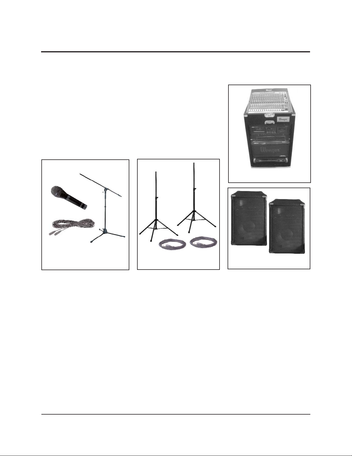
Before starting, make sure that you have
the following components (shown in
photographs below and at the right.
1. Series 500 Audio System Rack
2. Two Speakers
3. Two Speaker Cables
4. Two Speaker Stands
5 One Microphone
6. One Microphone Cable
7. One Microphone Stand
Series 500 Audio System Rack
Two Speakers
Two Speaker Stands and two
Speaker Cables
One Microphone, one
Microphone Stand, and one
Microphone Cable
These components are part of your basic Series 500 Audio System. The setup and
operation is described in this manual and in the manufacturer’s manuals that you
received.
If you ordered additional components not shown above, please refer to their
manufacturer’s manuals for setup and operation.
4
QUICK START — MICROPHONE AMPLIFICATION
A common use for your audio system is
amplifying live music or speech using
microphones. To get started:
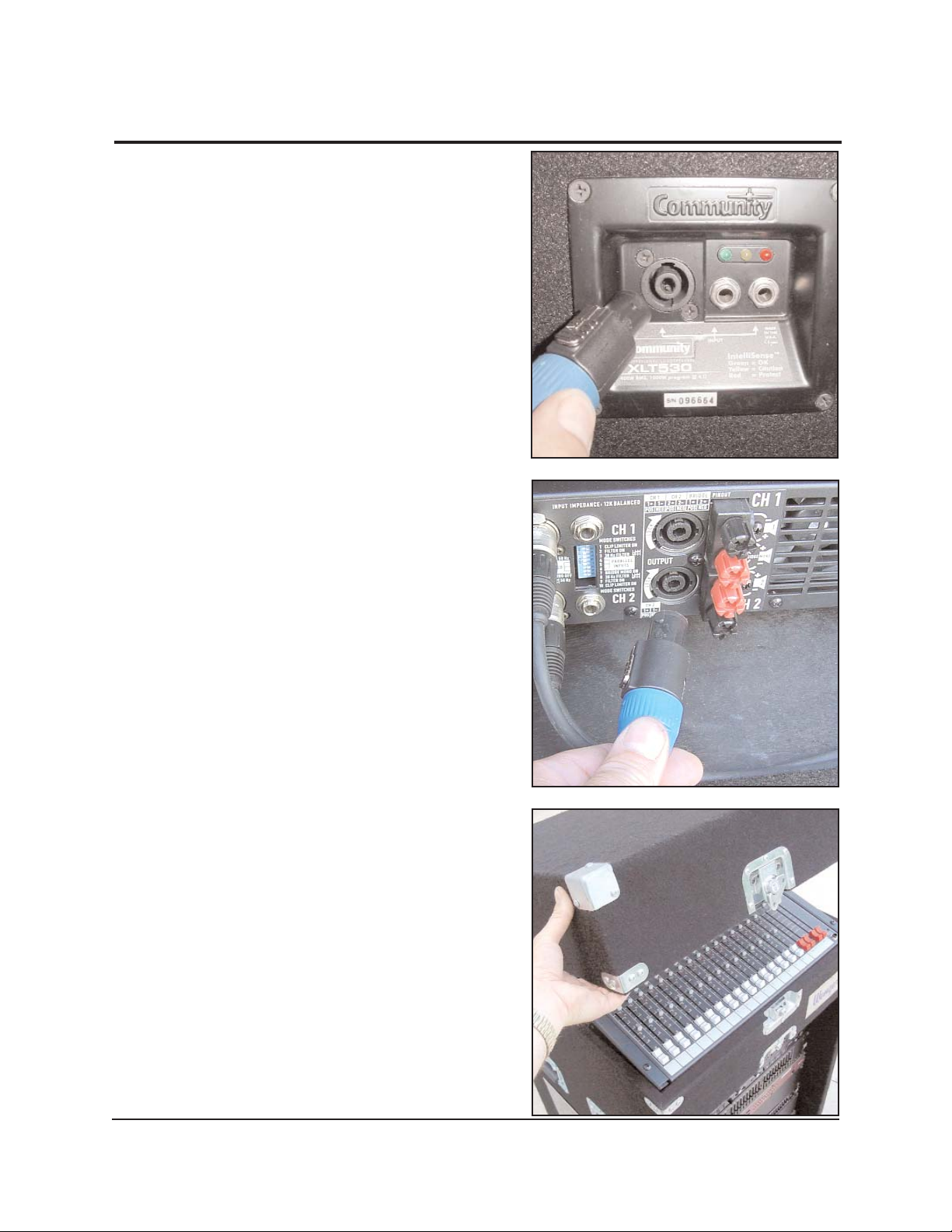
1. Connect speaker cables to your speakers.
Insert the plug at either end of the cable
into the speaker socket and rotate it
clockwise to lock. Choose any speaker
connector the cord will fit. Cable plugs
must be rotated to make electrical contact.
2. Remove the rear cover from the equipment
rack and connect the other ends of the
speaker cables to the amplifier outputs.
The amplifier is the bottom component in
the rack. For now, don't worry about which
amplifier output goes to which speaker.
These cables won't fit anywhere else so if
they are both plugged in and rotated to lock
in place, you've successfully made this
connection.
3. Remove the top cover from the audio rack.
5
QUICK START
— MICROPHONE AMPLIFICATION
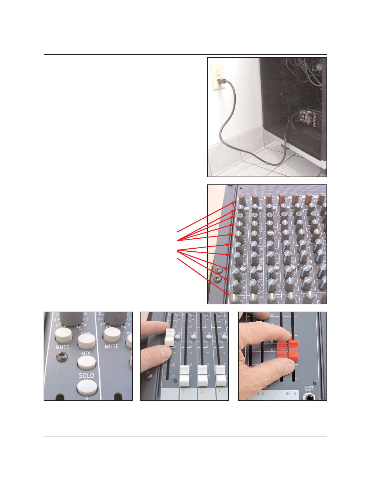
4. Plug in the power cord found when you
removed the rear cover.
This cord connects to the power distribution
unit, which in turn, powers all the other
components in the rack.
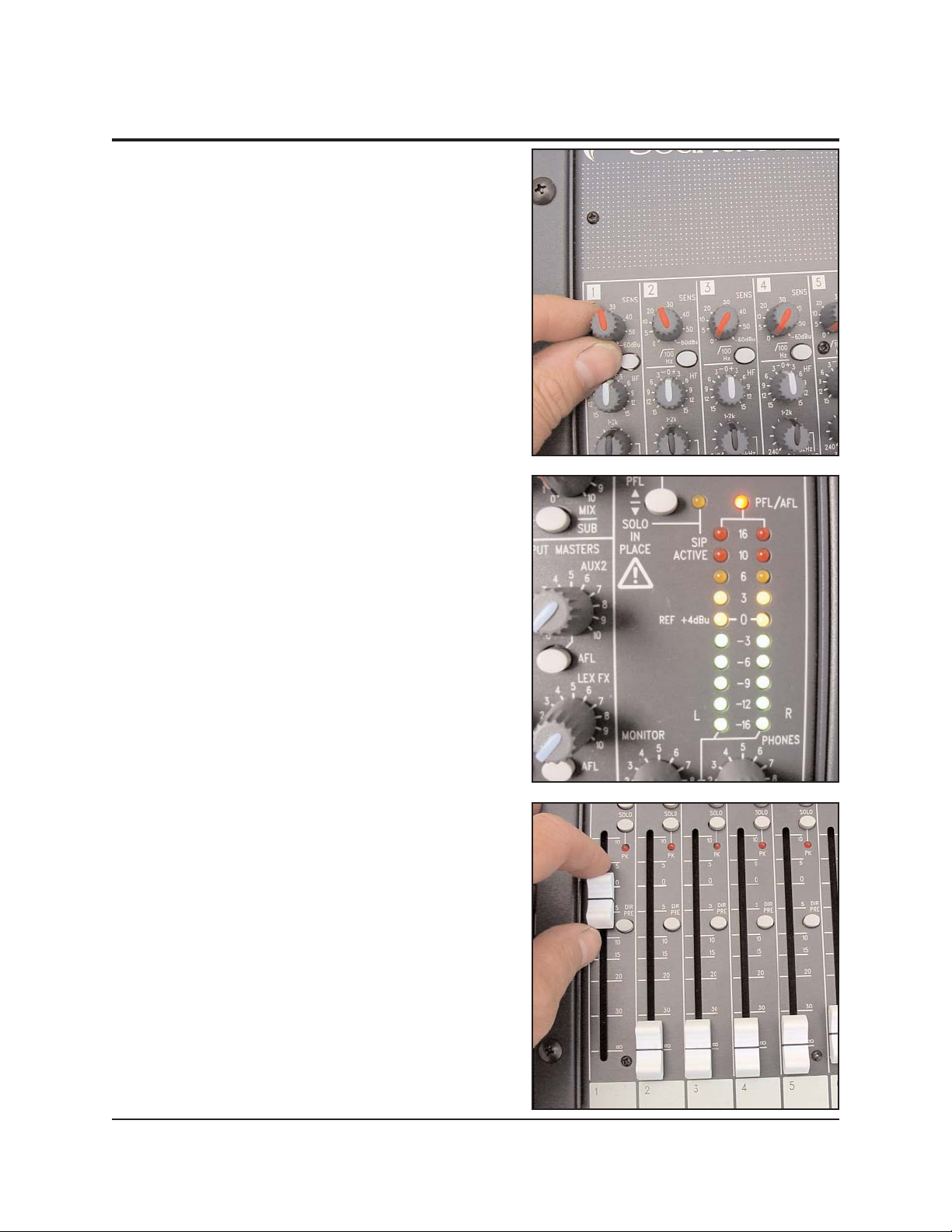
5. Adjust all control knobs, buttons and faders
for CHANNEL 1 to the settings shown.
Knob Position:
11:00
12:00
7:00
12:00
6
QUICK START
— MICROPHONE AMPLIFICATION
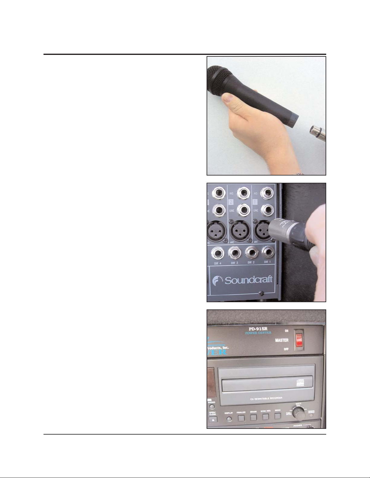
6. Using the microphone cable provided,
connect a microphone to the mixer on
CHANNEL 1
7. Remove the rack's front cover. Turn on the
main power switch in the far upper-right
corner of the rack.
This will provide power to all system
components. All individual components
should be powered up as indicated by their
front-mounted indicator lights.
7
8. Speak or play music into the microphone
and adjust the Channel 1 GAIN control knob
so that it lights most of the green indicators
on the right hand side of the mixer.
It's OK if louder inputs drive the indicators
into the yellow section. However, the GAIN
should NOT be set so high as to illuminate
the red indicators.
9. Adjust the volume of this microphone using
the Channel 1 Fader at the bottom LH
corner of the board.
This will affect the volume of only this
microphone.
QUICK START
— MICROPHONE AMPLIFICATION
8
QUICK START
— MICROPHONE AMPLIFICATION
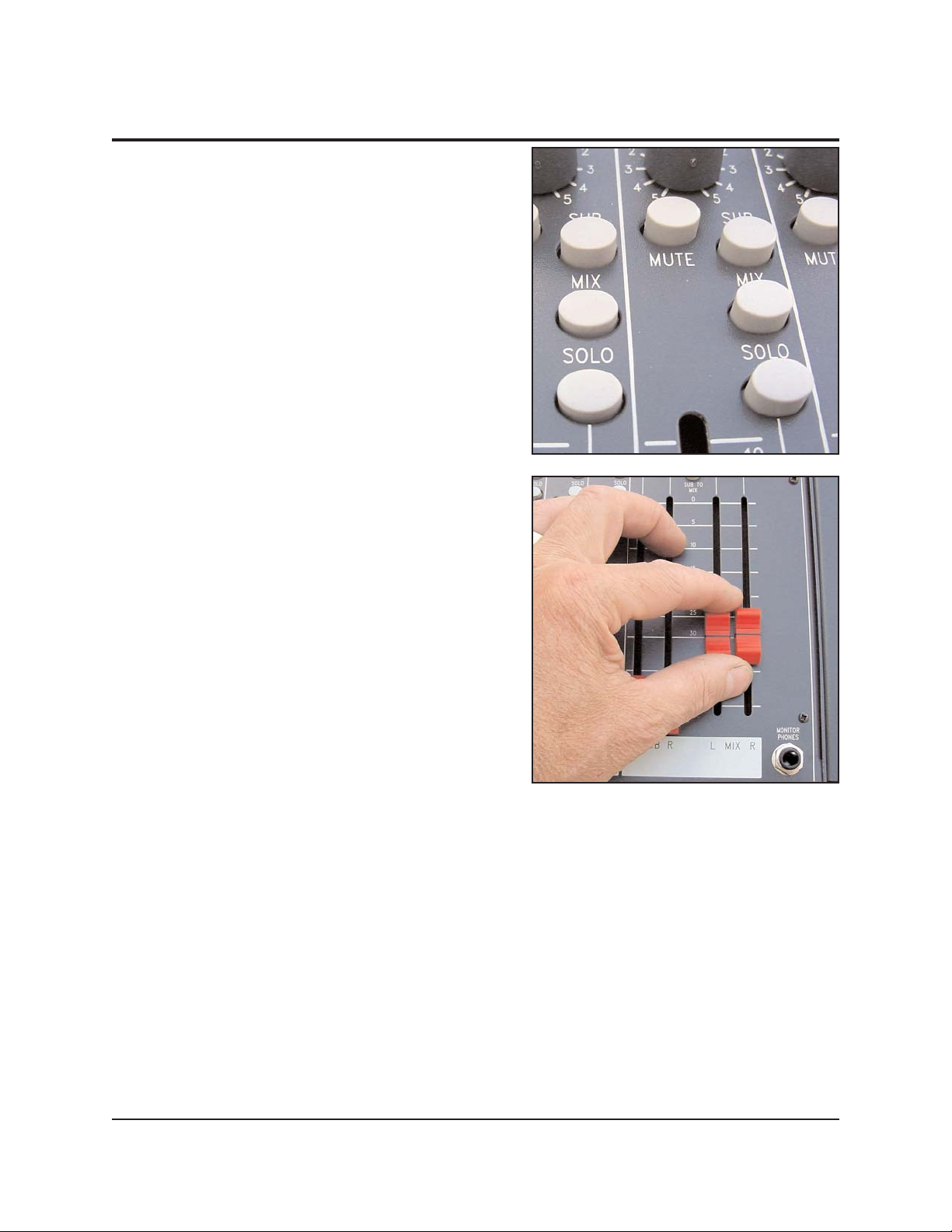
10. Additional channels can be set up in the
same way.
Note: When setting the gain control (step
8), only the
SOLO push button for the
channel being set should be depressed to
send its signal to the meters. All other
SOLO push buttons should be UP.
11. Once all input channels have been set up,
adjust the overall volume of the mix using
the faders at the lower right hand corner of
the board.
These faders will adjust the volume of all
inputs together.
9
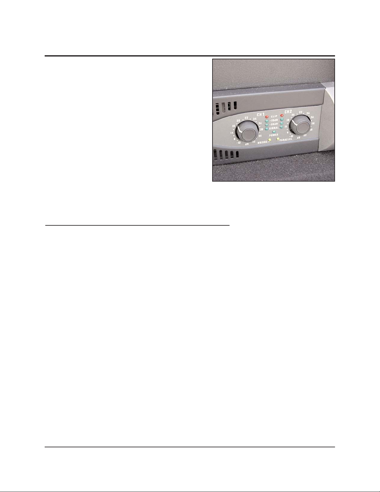
12. When the volume is adjusted at the proper
level for your venue, the MIX faders should
be approximately two-thirds of the way up.
If the volume at this setting is too high or
low, adjust the amplifier gain knobs (located
at the bottom right-hand corner of the rack)
to achieve the desired overall volume with
the MIX faders in that position.
Turning the
GAIN control knobs clockwise
will increase the volume. Turning
counterclockwise will decrease the volume.
(Both
GAIN control knobs should be set the
same.) This step will minimize the amount
of noise heard through the speakers during
quiet music passages, between speeches or anytime inputs are low.
Congratulations! Your system should be ready to amplify your next program.
If your audio system does NOT amplify as expected
, any of a number of cable
connections or settings may have been inadvertently changed. Detailed instructions
for proper connections and optimum settings can be found in this manual. Please refer
to the table of contents on the cover page for guidance.
Even if your system is playing, there are likely some adjustments in you may want to
make. Detailed instructions for further fine-tuning the system can be found on pages
22 to 32 in this manual and in the manufacturer's operation manuals contained in the
binder. Please refer to the table of contents on the cover page for more information.
QUICK START
— MICROPHONE AMPLIFICATION
10
QUICK START
— CD PLAYBACK
Note: The following Quick Start instructions
apply if you have a Wenger Model 502
Audio System containing a CD/cassette
player/recorder.
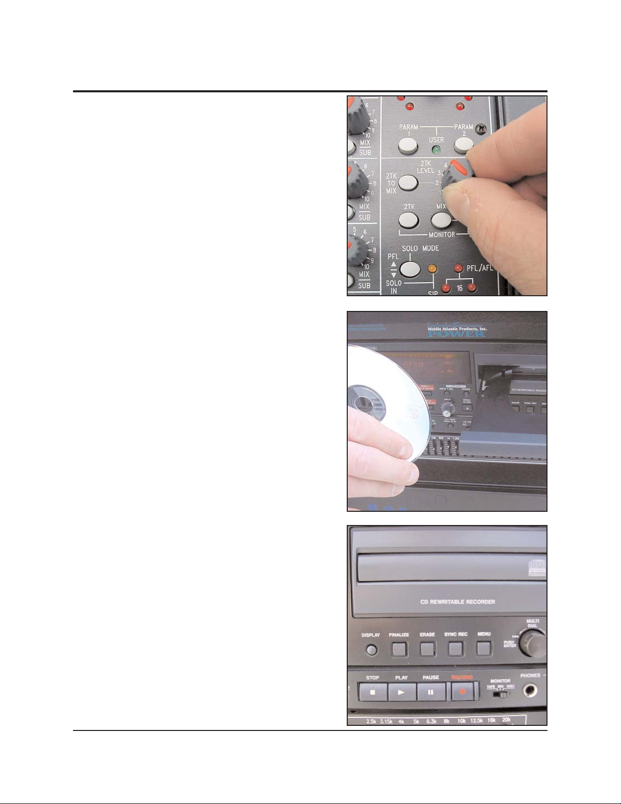
1. Adjust the control knob and push buttons
for the
2TK LEVEL to the settings shown.
Leave all other controls adjusted as they
were when you set up your amplification
system using the Microphone Amplification
Quick Start procedure. You may adjust the
microphone channel faders all the way
down to turn off the microphones if desired.
2. Press the OPEN/CLOSE push button and
insert a pre-recorded CD into the CDRW/Cassette Player/Recorder. Press the
OPEN/CLOSE push button again to close
the CD drawer.
3. Press the PLAY push button.
The CD player should now be playing
through the speakers. You should also
notice movement of the meters on the CDRW/Cassette Player/Recorder display.
 Loading...