

Page 1

Owner ’s Manual
Audio System Series 300
©Wenger Corporation 2005 Printed in USA 01/05 Part Number 126B927-3
Wenger Corporation, 555 Park Drive, P.O. Box 448, Owatonna, Minnesota 55060-0448
Questions? Call.....USA: (800) 733-0393 • International (call collect): (507) 455-4100 • www.wengercorp.com
CONTENTS
Safety . . . . . . . . . . . . . . . . . . . . . . . . . . . . . . . . . . . . . . . . . . .1
Important User Information . . . . . . . . . . . . . . . . . . . . . . . . . . .2
General . . . . . . . . . . . . . . . . . . . . . . . . . . . . . . . . . . . . . .2
Manufacturer . . . . . . . . . . . . . . . . . . . . . . . . . . . . . . . . .2
Installation . . . . . . . . . . . . . . . . . . . . . . . . . . . . . . . . . . .2
Intended Use . . . . . . . . . . . . . . . . . . . . . . . . . . . . . . . . .2
Quick Start — Before Starting . . . . . . . . . . . . . . . . . . . . . . . .3
Quick Start — Microphone Amplification . . . . . . . . . . . . . . . .4
Quick Start — CD Playback . . . . . . . . . . . . . . . . . . . . . . . . . .10
Quick Start — Cassette Playback . . . . . . . . . . . . . . . . . . . . .13
Quick Start — CD Recording . . . . . . . . . . . . . . . . . . . . . . . . .14
Tips for Recording on Cassette Tape Vs. CD . . . . . . . . . . . .16
CD-RW Recording . . . . . . . . . . . . . . . . . . . . . . . . . . . . .16
Cassette Recording . . . . . . . . . . . . . . . . . . . . . . . . . . . .16
Quick Start — Cassette Recording . . . . . . . . . . . . . . . . . . . .18
Important User Information . . . . . . . . . . . . . . . . . . . . . . . . . . .21
Operation Information . . . . . . . . . . . . . . . . . . . . . . . . . . .21
Intended Use . . . . . . . . . . . . . . . . . . . . . . . . . . . . . . . . .21
QUICK START
INSTRUCTIONS
NOTE: R
ead pages 2 to 19 before doing anything!
Wenger's goal is to provide a package of sophisticated, powerful audio components
configured with SIMPLICITY
in mind.
The individual components are pre-wired at the factory wherever possible. All initial
component settings are adjusted for you. Do not change any settings until you've had
a chance to use the system. Unless these settings have been altered, you should be
up and running in a few simple steps.
These Quick Start instructions will guide you through your audio system's setup
procedures. To familiarize yourself with your audio system, we suggest that you go
through each of the following steps in order. If you have any questions along the way,
please feel free to contact Wenger Customer Service at 1-800-887-7145.
Mixer Connection Diagram . . . . . . . . . . . . . . . . . . . . . . . . . . .21
Audio System Front Panel . . . . . . . . . . . . . . . . . . . . . . . . . . .22
Wiring Diagrams . . . . . . . . . . . . . . . . . . . . . . . . . . . . . . . . . . .23
Model 301 Wiring Diagram . . . . . . . . . . . . . . . . . . . . . . .23
Model 302 CD-RW Play-Cassette Record Diagram . . .24
Model 302 CD-RW Record-Cassette Play Diagram . . .25
System Settings . . . . . . . . . . . . . . . . . . . . . . . . . . . . . . . . . . .26
Before Operating . . . . . . . . . . . . . . . . . . . . . . . . . . . . . .26
Mixer to Graphic Equalizer Connections . . . . . . . . . . . .26
Graphic Equalizer To Amplifier Connections . . . . . . . . .26
CD-RW Playback-Cassette Recording Connections . . .26
CD-RW Record-Cassette Playback Connections . . . . .27
Change Record Function . . . . . . . . . . . . . . . . . . . . . . . .27
Initial Settings . . . . . . . . . . . . . . . . . . . . . . . . . . . . . . . . .27
Power Up the Audio System . . . . . . . . . . . . . . . . . . . . .28
Troubleshooting . . . . . . . . . . . . . . . . . . . . . . . . . . . . . . . . . . .29
Manufacturer's Owner Manuals . . . . . . . . . . . . . . . . . . . . . . .29
Replacement Part List . . . . . . . . . . . . . . . . . . . . . . . . . . . . . .30
Warranty . . . . . . . . . . . . . . . . . . . . . . . . . . . . . . . . . . . . . . . . .30
SAFETY
Warning! Do not use in wet or rainy conditions. Never connect the main power cord to a power
source in wet conditions. Do not alter the power cord or connect the power cord to
an ungrounded power source. Failure to observe this warning can result in electrical
shock or death!
Page 2

2
GENERAL
Copyright © 2005 by Wenger Corporation
All rights reserved. No part of the contents of this manual may be reproduced, copied, or transmitted in
any form or by any means including graphic, electronic, or mechanical methods or photocopying,
recording, or information storage and retrieval systems without the written permission of the publisher,
unless it is for the purchaser's personal use.
Printed and bound in the United States of America.
The information in this manual is subject to change without notice and does not represent a commitment
on the part of Wenger Corporation. Wenger Corporation does not assume any responsibility for any
errors that may appear in this manual.
In no event will Wenger Corporation be liable for technical or editorial omissions made herein, nor for
direct, indirect, special, incidental, or consequential damages resulting from the use or defect of this
manual.
The information in this document is not intended to cover all possible conditions and situations that
might occur. The end user must exercise caution and common sense when assembling or installing
Wenger Corporation products. If any questions or problems arise, call Wenger Corporation at 800-733-
0393.
MANUFACTURER
The Series 300 Audio System is manufactured by:
Wenger Corporation
555 Park Drive
Owatonna, MN 55060
1-507-455-4100 • 1-800-733-0393
www.wengercorp.com
INSTALLATION
• The Wenger Series 300 Audio System use must comply with local regulations and codes.
• All personnel (including all temporary workers) using the Wenger Series 300 Audio System must
read and understand this entire manual.
INTENDED USE
The Wenger Series 300 Audio System is intended for indoor use and outdoor use with fair weather
condition changes with some limitations. The Series 300 Audio System is not intended to be used in wet
or inclement weather conditions.
• Never exposure the Audio System components to wet or wet outdoor weather conditions.
• The system is not intended to be permanently installed
in outdoor environments.
• Exposure to wet conditions causes internal moisture that damages the loudspeaker cone, corrodes
electrical contacts, and presents an electrical shock hazard.
• Microphones are not intended to be used in wet conditions and must be protected from any
precipitation.
• Never expose the mixer to wet conditions or any precipitation.
IMPORTANT USER INFORMATION
Page 3
3
QUICK START
— BEFORE STARTING
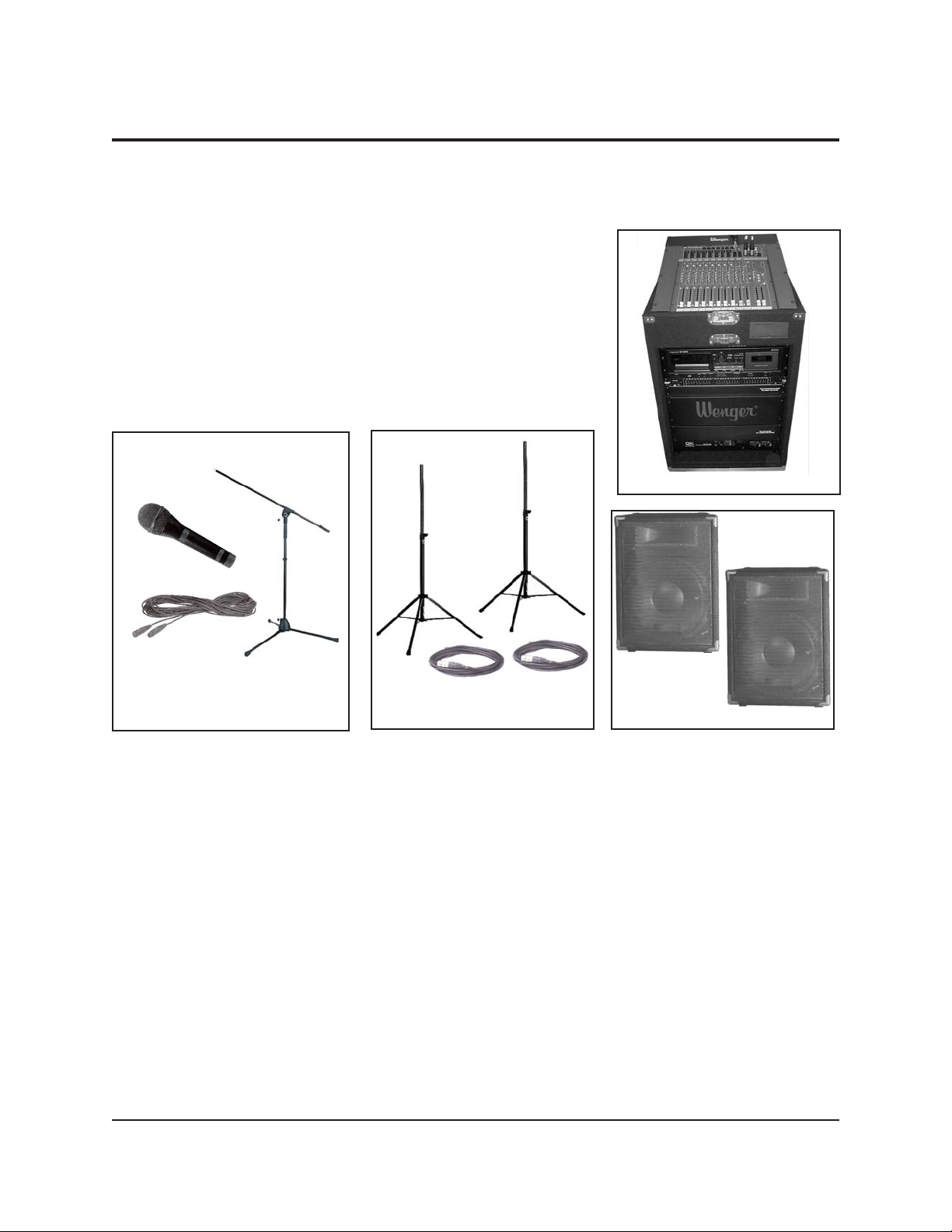
Before starting, make sure that you have
the following components (shown in
photographs below and at the right.
1. Series 300 Audio System Rack
2. Two Speakers
3. Two Speaker Cables
4. Two Speaker Stands
5 One Microphone
6. One Microphone Cable
7. One Microphone Stand
Series 300 Audio System Rack
Two Speakers
Two Speaker Stands and two
Speaker Cables
One Microphone, one
Microphone Stand, and one
Microphone Cable
These components are part of your basic Series 300 Audio System. The setup and
operation is described in this manual and in the manufacturer’s manuals that you
received.
If you ordered additional components not shown above, please refer to their
manufacturer’s manuals for setup and operation.
Page 4
4
QUICK START
— MICROPHONE AMPLIFICATION
A common use for your audio system is
amplifying live music or speech using
microphones. To get started:
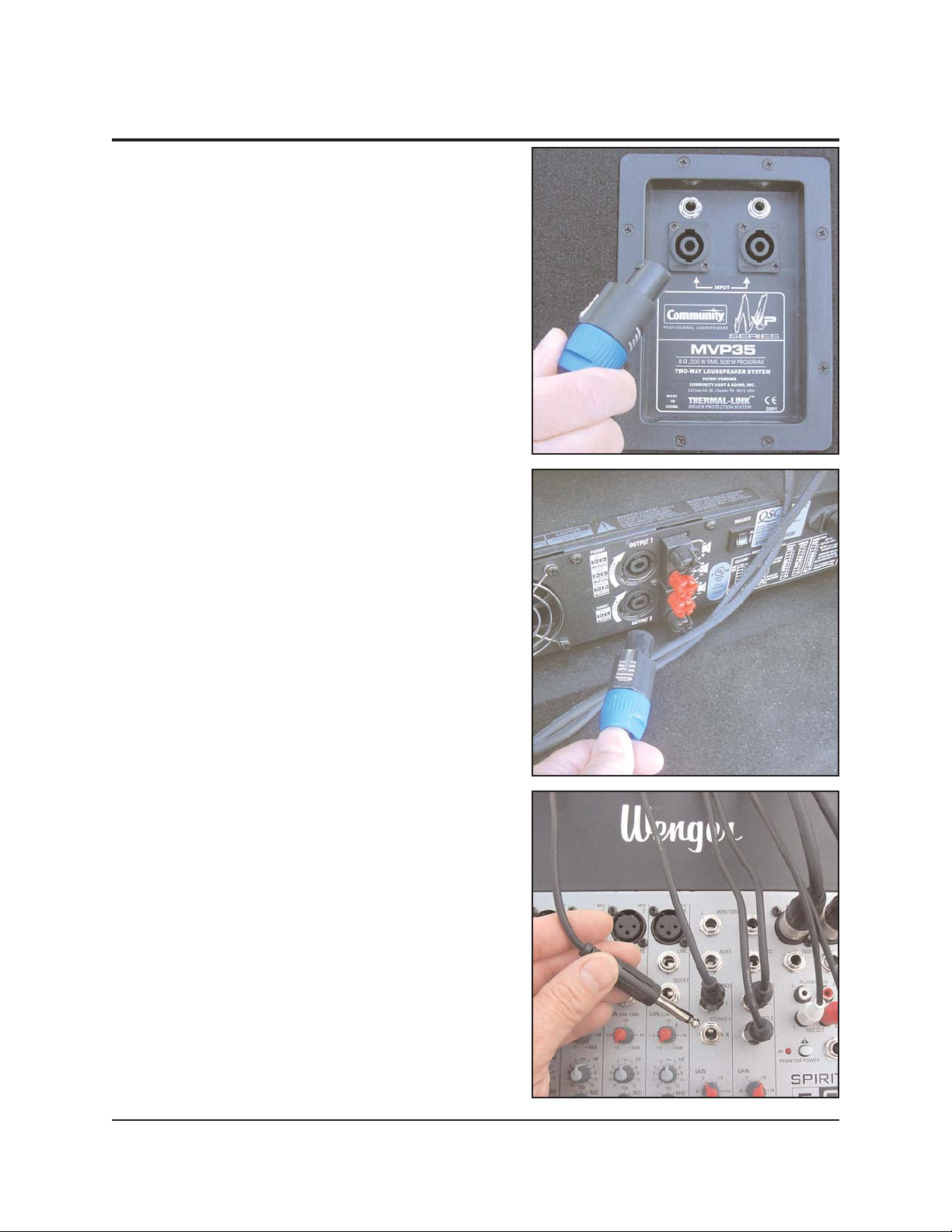
1. Connect speaker cables to your speakers.
Insert the plug at either end of the cable into
the speaker socket and rotate it clockwise to
lock. Choose any speaker connector the
cord will fit. Cable plugs must be rotated to
make electrical contact.
2. Remove the rear cover from the equipment
rack and connect the other ends of the
speaker cables to the amplifier outputs.
The amplifier is the bottom component in the
rack. For now, don't worry about which
amplifier output goes to which speaker.
These cables won't fit anywhere else so if
they are both plugged in and rotated to lock
in place, you've successfully made this
connection.
3. Remove the top cover from the audio rack.
If any cables had to be disconnected in
order for the cover to properly close,
reconnect them per the instructions found
under the cover.
Page 5
5
QUICK START
— MICROPHONE AMPLIFICATION
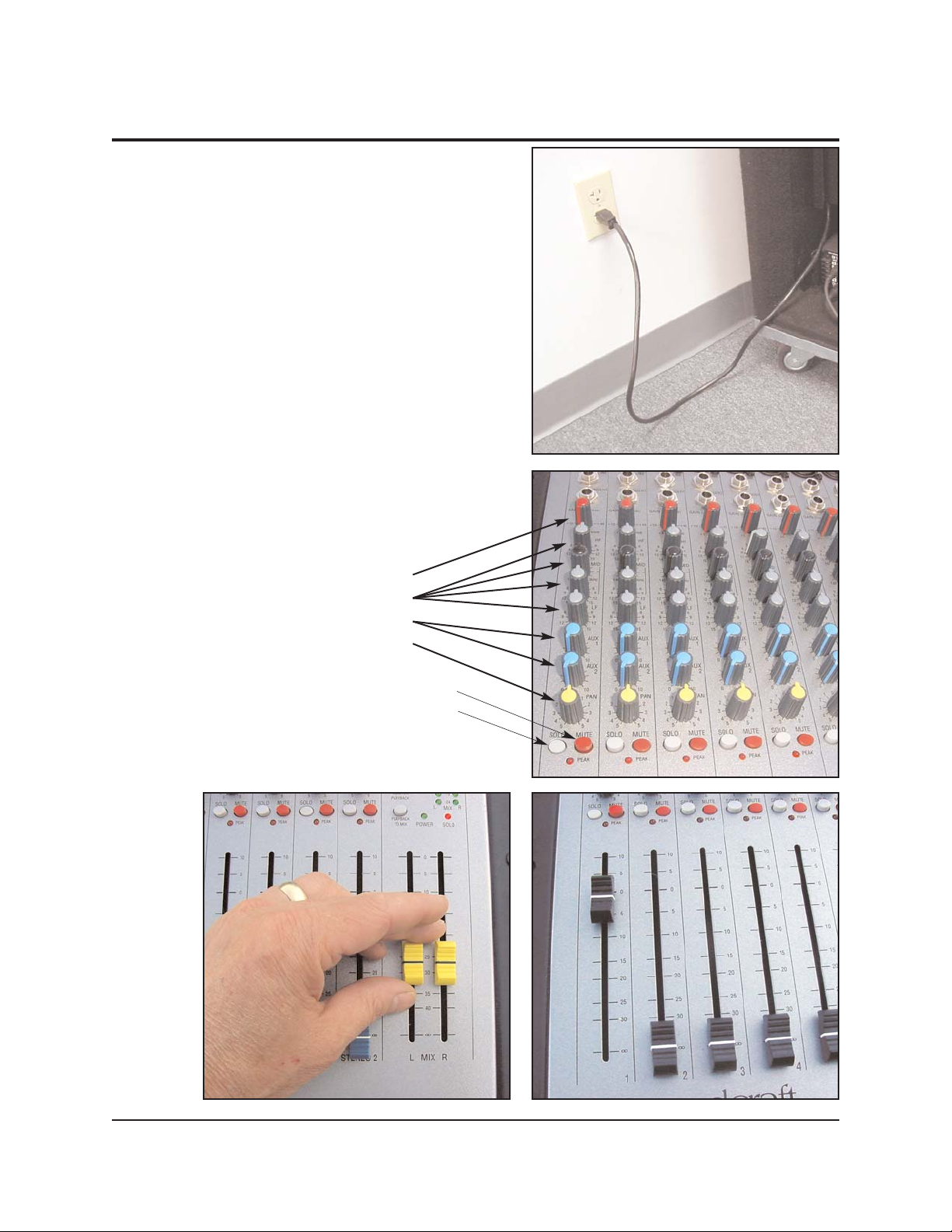
4. Plug in the power cord found when you
removed the rear cover.
This cord connects to the power distribution
unit, which in turn, powers all the other
components in the rack.
5. Adjust all control knobs, buttons and faders
for Channel 1 to the settings shown.
Knob Position:
7:00
12:00
7:00
12:00
Released (up position)
Depressed (down position)
Page 6
6
QUICK START
— MICROPHONE AMPLIFICATION
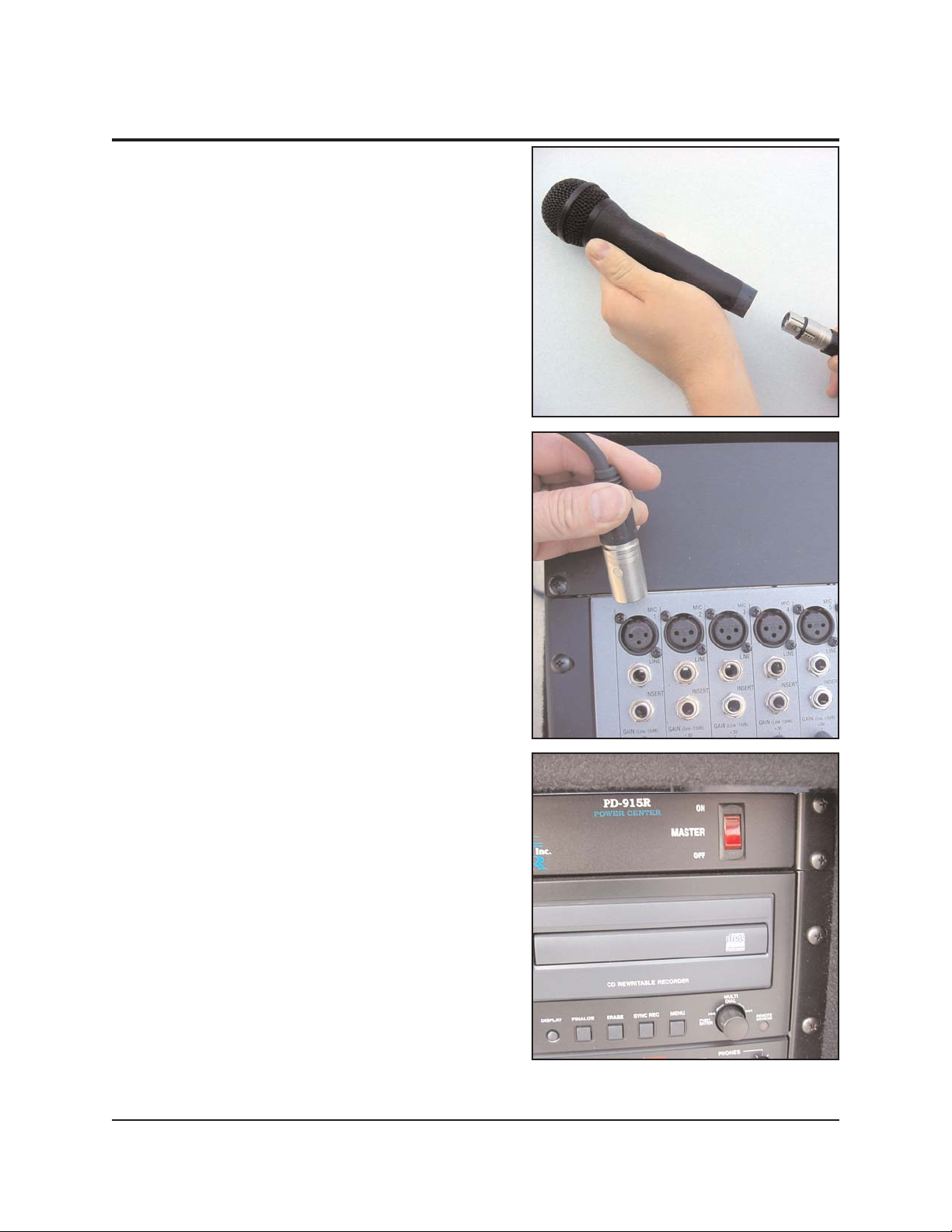
6. Using the microphone cable provided,
connect a microphone to the mixer on
CHANNEL 1.
7. Remove the rack's front cover. Turn on the
main power switch in the far upper-right
corner of the rack.
This will provide power to all system
components. All individual components
should be powered up as indicated by their
front-mounted indicator lights.
Page 7
7
QUICK START
— MICROPHONE AMPLIFICATION
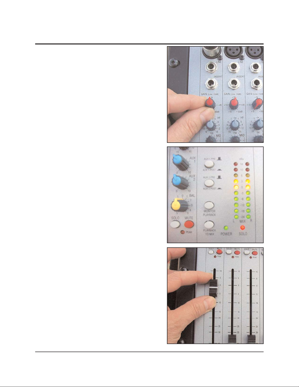
8. Speak or play music into the microphone
and adjust the Channel 1
GAIN control knob
so that it lights most of the green indicators
on the right hand side of the mixer.
It's OK if louder inputs drive the indicators
into the yellow section. However, the GAIN
should NOT be set so high as to illuminate
the red indicators.
9. Adjust the volume of this microphone using
the Channel 1 Fader at the bottom left hand
corner of the board.
This will affect the volume of only this
microphone.
Page 8
8
QUICK START
— MICROPHONE AMPLIFICATION
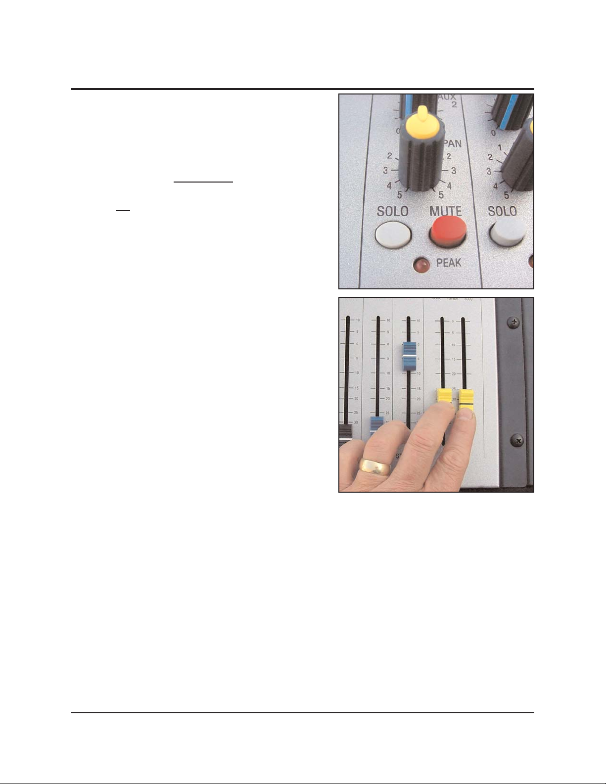
10. Additional channels can be set up in the
same way.
Note: When setting the gain control (step 8),
only the
SOLO button for the channel being
set should be depressed
to send its signal
to the meters. All other SOLO buttons should
be up
.
11. Once all input channels have been set up,
adjust the overall volume of the mix using
the faders at the lower right hand corner of
the board.
These faders will adjust the volume of all
inputs together.
Page 9
9
QUICK START
— MICROPHONE AMPLIFICATION
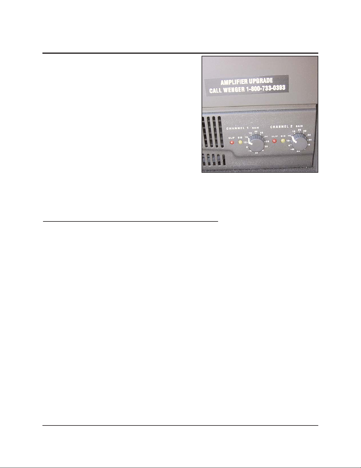
12. When the volume is adjusted at the proper
level for your venue, the MIX faders should
be approximately 2/3 of the way up. If the
volume at this setting is too high or low,
adjust the amplifier gain knobs (located at
the bottom right-hand corner of the rack) to
achieve the desired overall volume with the
MIX faders in that position.
Turning the
GAIN control knobs clockwise
will increase the volume. Turning counterclockwise will decrease the volume. (Both
GAIN control knobs should be set the same.)
This step will minimize the amount of noise
heard through the speakers during quiet music passages, between speeches or
anytime inputs are low.
Congratulations! Your system should be ready to amplify your next program.
If your audio system does NOT amplify as expected
, any of a number of cable
connections or settings may have been inadvertently changed. Detailed instructions
for proper connections and optimum settings can be found in this manual. Please refer
to the table of contents on the cover page for guidance.
Even if your system is playing, there are likely some adjustments in you may want to
make. Detailed instructions for further fine-tuning the system can be found on pages
21 to 30 in this manual and in the manufacturer's operation manuals contained in the
binder. Please refer to the table of contents on the cover page for more information.
Page 10

10
QUICK START
— CD PLAYBACK
Note: The following Quick Start instructions apply
if you have a Wenger Model 302 Audio
System containing a CD/cassette
player/recorder.
The next step is to playback a pre-recorded
program. Start with your favorite music CD. The
playback of CD's is controlled by the channel
labeled
STEREO 2.
1. Adjust the control knobs, push buttons and
faders for Channel
STEREO 2 to the settings
shown.
Leave all other controls adjusted as they
were when you set up your amplification
system using the Microphone Amplification
Quick Start procedure. You may adjust the
microphone channel faders all the way down
to turn off the microphones if desired.
2. Press the OPEN/CLOSE push button and
insert a pre-recorded CD into the CDRW/Cassette Player/Recorder. Press the
OPEN/CLOSE push button again to close the
CD drawer.
Knob Position:
12:00 o’clock
7:00 o’clock
12:00 o’clock
Down
Up
Page 11

11
QUICK START
— CD PLAYBACK
3. Press the PLAY button.
The CD player should now be playing
through the speakers. You should also
notice movement of the meters on the CDRW/Cassette Player/Recorder display.
4. Depress the SOLO button on Channel
STEREO 2 so its signal is sent to the meters.
Only the
SOLO button for the channel being
set should be depressed to send its signal
to the meters. All other
SOLO buttons should
be up.
5. Adjust the GAIN control knob so that the
input signal lights most of the green
indicators on the right hand side of the
mixer.
It's OK if louder inputs drive the indicators
into the yellow section. However, the Gain
should NOT be set so high as to illuminate
the red indicators.
Page 12

12
QUICK START
— CD PLAYBACK
6. Adjust the playback volume using the
Channel
STEREO 2 fader together with the
main mix faders located on the lower-right
corner of the mixer.
The Channel STEREO 2 fader will change
the volume of the CD playback, only. The
main mix faders will affect the volume of the
CD playback and any other input to the
board. (…like the microphones set up
earlier.)
If your audio system does NOT play as expected, any of a number of cable
connections or settings may have been inadvertently changed. Detailed instructions
for proper connections and optimum settings can be found in this manual. Please refer
to the table of contents on the cover page for guidance.
Even if your system is playing, there are likely some adjustments in you may want to
make. Detailed instructions for further fine-tuning the system can be found on pages
21 to 30 in this manual and in the manufacturer's operator's manuals contained in the
binder. Please refer to the table of contents on the cover page for more information.
Page 13

13
QUICK START
— CASSETTE PLAYBACK
Cassette playback is controlled by Channel
STEREO 1. For playing cassettes, follow the
instructions above using channel
STEREO 1
(instead of STEREO 2).
Cassette player controls are on the left side
of the player.
Page 14

14
QUICK START
— CD RECORDING
Now that you have successfully set up microphones for amplification and are able to
playback pre-recorded materials, the next step is to record your program.
Because your audio system was shipped from the factory ready for CD recording, we
recommend that you start by experimenting with
recording on CD's. As you become more familiar
with your system, you can make the wiring
changes outlined later in this section and record
on cassette tapes.
1. Press the
OPEN/CLOSE push button on the
CD player/recorder and insert a blank,
recordable CD. Press the
OPEN/CLOSE
push button again to close the CD drawer.
After a few seconds the CD player/recorder's
display will read:
0 Tr 0:00
2. Press the RECORD push button on the CD
recorder. After a few seconds, the first
available track will be queued and ready for
recording.
If the CD was blank, the display will read:
1 Tr 0:00
If the CD was not blank, the first number will
be that of the next available track.
Page 15

15
QUICK START
— CD RECORDING
3. With the program source playing (this could
be from the cassette player, instrument
pickups and/or the microphone inputs),
adjust the input level to the CD recorder.
Adjust the input level knob while watching
the level indicators on the CD recorder
display. They should pulse across the
display screen to the right as far as possible
without illuminating the red
OVER indicator.
4. Press PLAY to begin recording.
Record your program.
5. Press STOP when recording is complete.
The CD Recorder will write to the CD for a
few seconds and then display the number of
the last track recorded and its total length.
Recording is now complete.
This recording can now be played on this
CD recorder/player. W
ithout further
processing, your recording may not yet
be ready to be played on other CD
players. To use this disk in other CD
Players, the CD must be finalized.
To finalize the CD, press the FINALIZE push
button and then press the
MULTI-DIAL push
button. The display will count down for the
time remaining for finalization.
Page 16

16
QUICK START
— CD RECORDING
Function
Device Playback Record
CD/RW
Cassette
If your audio system does NOT record as expected, any of a number of cable
connections or settings may have been inadvertently changed. Detailed instructions
for proper connections and optimum settings can be found in this manual. Please refer
to its table of contents on the cover page for guidance.
Even if your system is playing, there are likely some adjustments in you may want to
make. Detailed instructions for further fine-tuning the system can be found on pages
21 to 30 in this manual and in the manufacturer's operator's manuals contained in the
binder. Please refer to the table of contents on the cover page for more information.
TIPS FOR RECORDING ON CASSETTE TAPE VS
. CD
The Wenger Model 302 Audio System has recording capabilities for both cassettes and
CD's. If configured as recommended in this manual, the system will play both CD's and
cassettes. However, changing between recording
on CD and cassette tape media
requires altering the system's wiring.
CD-RW RECORDING
Function
Device Playback Record
CD/RW
Cassette
As supplied from Wenger, this system is ready for CD-RW
recording (and playback.) In this configuration, the Cassette
deck is playback, only.
This system can be easily rewired for cassette recording. In
this configuration, system is ready for both Cassette
recording (and playback.) The CD-RW drive is playback,
only.
CASSETTE RECORDING
Page 17

17
CHANGING RECORDING DEVICE
To change from CD recording to cassette
recording (and back again), simply change the
Line Input cable connections at the Input of the
CD-RW/Cassette recorder. (The Line Input cable
runs from the mixer
REC OUT connection to the
CD-RW/Cassette recorder.
If you want to record on a CD, connect the
input cable to LINE INPUTS 1. (As supplied
from Wenger)
If you want to record on a Cassette, connect
the input cable to LINE INPUTS 2.
Page 18

18
QUICK START
— CASSETTE RECORDING
1. To set up the system for cassette recording,
connect the input cable running from the
REC OUT of the mixer to LINE INPUTS 2 of
the CD-RW/Cassette recorder.
2. Press the EJECT button on the cassette
player/recorder and insert a blank cassette.
Push the door closed.
3. Press RECORD.
You should see the red
REC symbol and
Pause symbol illuminated in the upper left
hand corner of the display.
Page 19

19
QUICK START
— CASSETTE RECORDING
4. With the program source playing (this could
be from the CD player, instrument pickups
and/or the microphone inputs), adjust the
input level to the Cassette recorder.
Adjust the input level knob while watching
the level indicators at the top of the cassette
recorder display. They should pulse across
the display screen to the right as far as
possible without illuminating the red
OVER
indicator.
5. Press PLAY to begin recording
The tape counter should begin to count up indicating that the tape is recording.
6. Press
STOP when recording is complete.
7. Rewind back to the beginning of the tape and play it back using the cassette
playback instructions above.
If your audio system did NOT record as expected
, any of a number of cable
connections or settings may have been inadvertently changed. Detailed instructions for
proper connections and optimum settings can be found on pages 21 to 30 in this
Owner's Manual. Please refer to the table of contents on the front cover for guidance.
Even if your system is working, there are likely some adjustments in you may want to
make. Detailed instructions for further fine-tuning the system can be found in this
Owner's Manual or the manufacturer's operator's manuals. Please refer to the table of
contents on the front cover for more information.
Page 20

20
Page 21

21
Main PARight and Left
Amplifier
Cassette, Tape or DAT Playback
Stage Feedback
Keyboard,
Compressor/Limiter
Guitar via DI Box
Vocal
Microphone
Headphones
Graphic Equalizer
Connection Diagram image is copied from Spirit Users Guide
Amplifier
Graphic Equalizer
MIXER CONNECTION DIAGRAM
IMPORTANT USER INFORMATION
INTENDED USE
The Audio System Series 300 is intended for indoor use or outdoor use with fair weather conditions.
• Never exposure the Audio System components to wet or wet outdoor weather conditions.
• The system is not intended to be permanently installed
in outdoor environments.
• Exposure to wet conditions causes internal moisture that damages the loudspeaker cone, corrodes
electrical contacts, and presents an electrical shock hazard.
• Microphones are not intended to be used in wet conditions and must be protected from any
precipitation.
• Never expose the mixer to wet conditions or any precipitation.
OPERATION INFORMATION
The following pages contain detail information regarding the set up, operation, replacement parts, and
warranty.
If you have questions or problems, contact Wenger Corporation Customer Service by telephone, email,
or by writing to the address on the cover page.
Page 22

22
Power Distribution Unit 120 VAC
Receptacle
Power Distribution Unit On-Off
Switch
Audio Amplifier On-Off
Switch
Audio Amplifier Channel 2
Gain Control
Audio Amplifier Channel 1
Gain Control
Graphic Equalizer Input Level
Control
Graphic Equalizer On-Off
Switch
Model 302 CD-RW/Cassette Player
Model 301 Shelf
AUDIO SYSTEM FRONT PANEL
Mixer
Power Distribution Unit
Drawer
1 Unit Plate
2 Unit Plate
Model 302 shown
Page 23

23
6-foot Cable,
XLR Connectors
WIRING DIAGRAMS
MODEL 301 WIRING DIAGRAM
Note: The wiring diagram perspective is the rear of
the Audio System Equipment Rack.
Note: This area is magnified.
Page 24

24
WIRING DIAGRAMS
CONTINUED
MODEL 302 CD-RW PLAYBACK-CASSETTE PLAY/RECORD WIRING DIAGRAM
Cable, RCA to 1/4-
inch Connectors
Cable, RCA to
RCA Connectors
6-foot Cable,
XLR Connectors
Function
Device Playback Record
CD/RW
Cassette
Note: The wiring diagram perspective is
the rear of the Audio System
Equipment Rack.
View from rear of the
Mixer
Page 25

25
WIRING DIAGRAMS
CONTINUED
MODEL 302 CD-RW PLAY/RECORD - CASSETTE PLAYBACK WIRING DIAGRAM
6-foot Cable,
XLR Connectors
Cable, RCA to 1/4-
inch Connectors
Cable, RCA to
RCA Connectors
Function
Device Playback Record
CD/RW
Cassette
View from rear of the
Mixer
Note:
The wiring diagram perspective is
the rear of the Audio System
Equipment Rack.
Note:: The
Audio System is shipped from
the factory with these wiring
connections.
Page 26

26
SYSTEM SETTINGS
BEFORE OPERATING
Refer to the Audio System Mixer Users Guide for additional information regarding set up and component
connections.
1. Make sure the Audio System Power Distribution Unit
ON-OFF Switch is in the OFF Position.
2. Connect the power cord from the Power Distribution Unit to a grounded, 120 VAC power source. All
components are powered by this component.
3. Connect the Amplifier
CHANNEL 1 OUTPUT connector to a Loudspeaker INPUT connector and the
Amplifier CHANNEL 2 OUTPUT connector to the other Loudspeaker INPUT connector with the 50-foot
speaker cables.
4. Make sure that the Mixer, Graphic Equalizer, Amplifier, and other component power switches are
OFF and the Mixer and Amplifier level controls are set to the lowest levels. Refer to the Audio
System Owner’s Manual for additional information.
5. Connect the power cords from the Mixer, Graphic Equalizer, and Amplifier to the Power Distribution
Unit.
6. Place the speakers and microphones where they will be used during the performance. Avoid placing
microphones directly in front of speakers.
MIXER TO GRAPHIC EQUALIZER CONNECTIONS
Make sure that the Power Distribution Unit ON-OFF switch and the Graphic Equalizer ON-OFF switch is
OFF before connecting any cables. Refer to the wiring diagram on page 23.
1. Using a six-foot XLR Cable, connect the Mixer
MIX R Connector to Graphic Equalizer INPUT R
Connector.
2. Using a six-foot XLR Cable, connect the Mixer MIX L Connector to Graphic Equalizer INPUT L
Connector.
GRAPHIC EQUALIZER TO AMPLIFIER CONNECTIONS
Make sure that the Power Distribution Unit ON-OFF switch and the Amplifier ON-OFF switch is OFF before
connecting any cables. Refer to the wiring diagram on page 23.
1. Using a six-foot XLR Cable, connect the Graphic Equalizer OUTPUT L Connector to Amplifier CH 1
Connector.
2. Using a six-foot XLR Cable, connect the Graphic Equalizer OUTPUT R Connector to Amplifier CH 2
Connector.
CD-RW PLAYBACK AND CASSETTE RECORDING/PLAYBACK CONNECTIONS
Note:
LINE OUTPUTS 1
connect to the CD-RW Recorder.
LINE OUTPUTS 2 connect to the Cassette Deck and the CD-RW Recorder. If both are playing,
the Cassette Deck has priority and the CD-RW Recorder is not heard.
Note:
LINE INPUTS 1 connect to the CD-RW Recorder.
LINE INPUTS 2 connect to the Cassette Deck
Make sure that the Power Distribution Unit ON-OFF switch is off before connecting any cables. Refer to
the wiring diagram on page 24.
1. Using a RCA/Phono to 1/4-inch Internal Patch Cable, connect the CD-RW RCA Connector
LINEOUT
1 R
and LINEOUT 1 L to the Mixer 1/4-inch Connector STEREO 2 R and STEREO 2 L.
2. Using a RCA/Phono Internal Patch Cable, connect the Mixer RCA Connector REC OUT R and REC
OUT L
to Cassette RCA Connector LINE INPUTS 2 R and LINE INPUTS 2 L.
Page 27

27
SYSTEM SETTINGS
(CONTINUED)
3. Using RCA/Phono to 1/4-inch Internal Patch Cables, connect the Cassette RCA Connector LINEOUT
2 R
and LINEOUT 2 L to Mixer 1/4-inch Connector STEREO 1 R and STEREO 1 L.
4. Connect the Power Cord from the CD-RW Recorder/Cassette Deck to an unused receptacle on the
Power Distribution Unit.
CD-
RW RECORD/PLAYBACK AND CASSETTE PLAYBACK CONNECTIONS
Note: LINE OUTPUTS 1 connect to the CD-RW Recorder.
LINE OUTPUTS 2 connect to the Cassette Deck and the CD-RW Recorder. If both are playing,
the Cassette Deck has priority and the CD-RW Recorder is not heard.
Note: LINE INPUTS 1 connect to the CD-RW Recorder.
LINE INPUTS 2 connect to the Cassette Deck
Make sure that the Power Distribution Unit
ON-OFF switch is off before connecting any cables. Refer to
the wiring diagram on page 25.
1. Using RCA/Phono to 1/4-inch Internal Patch Cables, connect the CD-RW RCA Connector LINEOUT
1 R
and LINEOUT 1 L to Mixer RCA Connector STEREO 2 R and STEREO 2 L.
2. Using a RCA/Phono Internal Patch Cable, connect the Mixer RCA Connector REC OUT R and REC
OUT L
to Cassette RCA Connector LINE INPUTS 1 R and LINE INPUTS 1 L.
3. Using a RCA/Phono to 1/4-inch Internal Patch Cable, connect the Cassette RCA Connector
LINEOUT 2 R and LINEOUT 2 L to Mixer RCA Connector 1/4-inch Connector STEREO 1 R and
STEREO 1 L.
4. Connect the Power Cord from the CD-RW Recorder/Cassette Deck to an unused receptacle on the
Power Distribution Unit.
CHANGE RECORD FUNCTION
To change from CD-RW recording to Cassette recording (or back again), reverse the cables on the back
of the CD-RW/Cassette recorder as follows.
1. Swap the cables in
LINEOUT 1 R and LINEOUT 1 L and LINEOUT 2 R and LINEOUT 2 L (the cables in
LINEOUT 1 R
and LINEOUT 1 L are now in LINEOUT 2 R and LINEOUT 2 L). Likewise, the cables in
LINEOUT 2 R
and LINEOUT 2 L are now in LINEOUT 1 R and LINEOUT 1 L.
INITIAL SETTINGS
1. Make sure that the Mixer, Amplifier, and CD-RW/Cassette power switches are in the OFF position.
2. Set the Amplifier
CHANNEL 1 and CHANNEL 2 GAIN controls to 25 percent.
3. Set the Mixer as follows.
a. Turn the GAIN CONTROL at each channel (red knob) fully counterclockwise.
b. Move the Faders to 0.
c. Set the MASTER VOLUME (yellow sliders) to 0.
Note: Make sure that the
SOLO and MUTE push buttons (above each Fader slide switch) are in the up
position.
4. Set the Graphic Equalizer
INPUT LEVEL to the center detent (0 dB) and all sliders to the center
detent (0 dB) and the BYPASS push button in the up position (EQ Active).
CD
-RW PLAYBACK AND CASSETTE RECORDING/PLAYBACK CONNECTIONS CONTINUED
Page 28

28
POWER UP THE AUDIO SYSTEM
1. Place the Power Distribution Unit power
switch into the ON position.
2. Make sure that the program sources
(microphone, CD-RW/Cassette player,
musical instruments) are present at the
appropriate input channels.
3. Power up the Mixer, audio sources, and
musical instruments. Refer to the
component manufacturer’s User Guides
for additional operating information.
4. For Mode 302, press the CD-RW
Recorder/Cassette Deck
POWER push
button.
5. Apply a performance level signal to the
system.
6. Turn on power to the Amplifier. The
yellow
CHANNEL 1 and CHANNEL 2
SIGNAL
LEDs will illuminate if channel
input signals are detected.
7. Turn on the Graphic Equalizer.
8. On the Mixer first channel with an input:
a. Press the
SOLO push button.
b. Turn the
GAIN CONTROL (red knob)
clockwise until the Meter display is in
the amber section with occasional
peaks to the first red LED.
c. Release the
SOLO push button
(place into the upper position).
d. Repeat steps 8a, 8b, and 8c on any
other input channels.
e. Adjust the Master Volume Faders (
MIX R and MIX L) to about two-thirds of the way up to
approximately 15.
f. If feedback is detected, reduce the Amplifier Gain or make an adjustment with the Graphic
Equalizer sliders.
9. On the Amplifier:
a. Adjust the Amplifier
CHANNEL 1 and CHANNEL 2 GAIN controls until the desired loudspeaker
volume is achieved.
b. Make sure that the CHANNEL 1 and CHANNEL 2 CLIP LEDs are not illuminated. Occasional
flashes are normal for very loud operation. However, if a
CHANNEL 1 CLIP or CHANNEL 2 CLIP
LED stays illuminated, reduce the CHANNEL 1 GAIN or CHANNEL 2 GAIN level.
c. Once the Amplifier Gain is set, adjust the system volume with the Master Faders.
10. Make sure that the program sources (microphone, CD-RW/Cassette player, musical instruments) are
present at the appropriate input channels.
11. Adjust the Graphic Equalizer sliders to achieve the desire sound quality.
12. Press the Graphic Equalizer
BYPASS switch in and out and adjust INPUT LEVEL so that the output
level is equal when the
BYPASS switch is pressed in and out.
SYSTEM SETTINGS
(CONTINUED)
Gain Control
Master Volume Faders
Power On-Off
Fader
Meter
Page 29

29
MANUFACTURER
’S OWNER MANUALS
The following manufacturer’s owner manuals are contained in this binder.
• Spirit Folio Users Guide
• Community MVP™ Series Owners Manual
• Middle Atlantic Products, Inc. Rackmount Power Strip
• QSC RMX™ Series 850 Amplifier
• Rane SEQ 30S Stereo Graphic Equalizer Operators Manual
TROUBLESHOOTING
Refer to each manufacturer’s owner manual in the binder for detailed troubleshooting information.
1. Verify all cables are firmly connected.
2. Verify power is supplied to all components. Are there visible lights on each component?
3. Verify channels on the power amplifier are turned up. They should be set about three-quarters of the
way up (turned clockwise).
4. Verify mixer settings are set so that volume sources are loud enough to hear an audible signal.
Page 30

30
WARRANTY
Wenger Corporation will act as a contact and provide support for the Audio System. Call Wenger
Corporation Customer Service with any questions or problems at 1-800-887-7145. While Wenger
Corporation will coordinate customer service with each component manufacturer, the manufacturer of
each Audio System component is responsible for that component warranty. The front pocket of the
Owner’s Binder, located in the Audio System Drawer, contains several manufacturer’s warranty cards. It
is important that these warranty cards are filled out with serial numbers and registered with each
manufacturer within 30 days after receipt of the system. The warranty for each component is as follows:
Component Warranty Extended Warranty
Community Speakers 5 Years NA
Soundcraft/Spirit Mixing Console 1 Year NA
QSC Amplifier 1 Year 3 Years
Rane Equalizer 2 Years 3 Years
Sabine Feedback Extermination Unit 1 Year NA
Tascam CD/Cassette Player 1 Year NA
REPLACEMENT PART LIST
Model 301 Qty Model 302 Qty
Rack-mounted Components: Rack-mounted Components:
Rack-mountable Case 1 Rack-mountable Case 1
Caster, Swivel 2 Caster, Swivel 2
Caster, Swivel, lockable 2 Caster, Swivel, lockable 2
Mixer, 8 channel 1 Mixer, 8 channel 1
Power Distribution Unit 1 Power Distribution Unit 1
Shelf, rackmountable, 5-1/4" 1 CD Player/Cassette Player Recorder 1
Graphic Equalizer 1 Graphic Equalizer 1
Drawer, rackmountable, 7" 1 Drawer, rackmountable, 7" 1
Power Amplifier 1 Power Amplifier 1
Speaker/Microphone Stand Storage Bag 1 Speaker/Microphone Stand Storage Bag 1
Blank Panel, 1-3/4" 1 Blank Panel, 1-3/4" 1
Blank Panel, 3-1/2" 2 Blank Panel, 3-1/2" 2
Cable, internal patch, 6 ft, XLR Connectors 2 Cable, internal patch, 6 ft, XLR Connectors 2
Cable, internal patch, 3 ft, XLR Connectors 2 Cable, internal patch, 3 ft, XLR Connectors 2
Rackscrew, washer, ¾" 38 Cable, RCA/Phono to 1/4-inch Connectors 4
Cable, RCA/Phono to Connectors, dual 1
Speaker/Microphone Storage Bag 1
Rackscrew, washer, ¾" 38
S
peaker Kit (2):
S
peaker Kit (2):
Loudspeaker, LF 1 x 15", 2-way 1 Loudspeaker, LF 1 x 15", 2-way 1
Cable, 50 ft, ¼" to Neutrik Speakon Connector 1 Cable, 50 ft, ¼" to Neutrik Speakon Connector 1
Loudspeaker dust cover 1 Loudspeaker dust cover 1
Speaker Stand Speaker Stand:
Adjustable tripod speaker stand 2 Adjustable tripod speaker stand 2
Microphone Set: Microphone Set:
Microphone, dynamic 1 Microphone, dynamic 1
Tripod microphone stand with boom 1 Tripod microphone stand with boom 1
Cable, 16 ft, XLR connectors 1 Cable, 16 ft, XLR connectors 1
 Loading...