

Page 1
WORK STATION
WITH LIGHT
For replacement parts visit
WENPRODUCTS.COM
Model # WB4723
bit.ly/wenvideo
IMPORTANT:
Your new tool has been engineered and manufactured to WEN’s highest standards for dependability, ease
of operation, and operator safety. When properly cared for, this product will supply you years of rugged,
trouble-free performance. Pay close attention to the rules for safe operation, warnings, and cautions. If
you use your tool properly and for its intended purpose, you will enjoy years of safe, reliable service.
NEED HELP? CONTACT US!
Have product questions? Need technical support?
Please feel free to contact us at:
800-232-1195
(M-F 8AM-5PM CST)
techsupport@wenproducts.com
WENPRODUCTS.COM
NOTICE: Please refer to wenproducts.com for the most up-to-date instruction manual.
Page 2

TABLE OF CONTENTS
Product Specifications
Important Safety Rules
Electrical Information
Maintenance
Exploded View & Parts List
Assembly & Adjustments
Warranty Statement
PRODUCT SPECIFICATIONS
Model Number:
Maximum Weight Capacity:
Table Top Dimensions:
Table Height:
Drawer Dimensions:
Power Outlet Rating:
Power Cord Length:
Replacement Bulb:
Assembled Product Dimensions:
Product Net Weight:
2
3
4
5
6
8
14
WB4723
Total - 514 lbs (Evenly Distributed)
Table Top - 220 lbs
Bottom Shelf - 200 lbs
Each Drawer - 25 lbs
Top Shelf - 44 lbs
47-1/4 x 23-1/2 x 5/8 inch
35 inch
20 x 17-3/4 x 2-1/2 inch
3 Outlets, AC 120V, 60Hz, 13A
80 inch
13W T5 Fluorescent
47-3/8 x 25 x 61-3/4 inch
88.5 lbs
2
Page 3

IMPORTANT SAFETY RULES
Safety is a combination of common sense, staying alert and knowing how your item works.
SAVE THESE SAFETY INSTRUCTIONS.
WARNING: To avoid mistakes and serious injury, read and understand this entire instruction manual.
Learn the tool’s applications, limitations, and possible hazards. These safety rules cannot address every
possible scenario you may encounter, so please use common sense and caution when using the tool.
WORK AREA SAFETY
1. Keep your work area clean, uncluttered, and well lit. Cluttered areas invite injuries and accidents. Keep the
ground clear of tripping hazards. Do not work on floor surfaces that are slippery with sawdust or wax.
2. Observe work area conditions. Keep bystanders at a safe distance from the work area. Never allow children or
pets near the tool.
PERSONAL SAFETY
1. Wear ANSI Z87.1-approved safety goggles, work gloves and closed-toe shoes during assembly and use. Wear
additional safety gear as required by local, state and federal regulations.
2. Stay alert - watch what you’re doing and use common sense when using the tool. Do not use while you are tired
or under the influence of drugs, alcohol or medication that may affect your ability to properly use the tool. A moment of inattention may result in serious personal injury.
3. Do not overreach. Keep proper footing and balance at all times.
WORK STATION USE & CARE
1. For maximum stability, assemble and use the work station only on a flat, level surface.
2. Do not modify or use the tool to do a job for which it was not designed. Unauthorized modification may damage the tool and/or cause personal injuries.
3. Do not exceed the rated weight capacity (total - 514 lbs, table top - 220 lbs, bottom shelf - 200 lbs, each drawer
- 25 lbs, top shelf - 44 lbs). Make sure the weight is evenly distributed. Be aware of dynamic loading, as sudden
movement may briefly create excess load, causing product to fail.
4. Do not step, climb or sit on the work table.
5. Assemble and use the work station indoors only. Do not expose power tools to rain or wet conditions. Water
entering the electrical system will increase the risk of electric shock.
6. Always check for damaged or worn out parts before using the tool. Check for alignment of moving parts, jamming, breakage, improper mounting, or any other conditions that may affect the tool’s operation. Any part that is
damaged should be properly repaired or replaced before use.
7. Maintain tools properly. Always keep tools clean and in good working order. Store the unit in a dry, secure
place out of the reach of children. Inspect the tool for good working condition prior to storage and before re-use.
8. Power tool plugs must match the outlet. Never modify the plug in any way. Do not use any adapter plugs with
earthed (grounded) power tools. Unmodified plugs and matching outlets will reduce risk of electric shock.
3
Page 4
ELECTRICAL INFORMATION
GROUNDING INSTRUCTIONS
In the event of a malfunction or breakdown, grounding provides the path of
least resistance for an electric current and reduces the risk of electric shock.
This tool is equipped with an electric cord that has an equipment grounding
conductor and a grounding plug. The plug MUST be plugged into a matching
outlet that is properly installed and grounded in accordance with ALL
local codes and ordinances.
Do not modify the plug provided. If it will not fit the outlet, have the proper
outlet installed by a licensed electrician.
IMPROPER CONNECTION of the equipment grounding conductor can result in electric shock. The conductor with the green insulation (with or without yellow stripes) is the equipment grounding conductor. If repair or
replacement of the electric cord or plug is necessary, do not connect the equipment grounding conductor to a live
terminal.
In all cases, make certain the outlet in question is properly grounded. If you are not sure, have a licensed electrician check the outlet.
GUIDELINES FOR USING EXTENSION CORDS
When using an extension cord, be sure to use one heavy enough to carry the current your product will draw. An
undersized cord will cause a drop in line voltage resulting in loss of power and overheating. The table below shows
the correct size to be used according to cord length and nameplate ampere rating. When in doubt, use a heavier
cord. The smaller the gauge number, the heavier the cord.
REQUIRED GAUGE FOR EXTENSION CORDS
AMPERAGE
25 ft. 50 ft. 100 ft. 150 ft.
13A 14 gauge 12 gauge Not Recommended
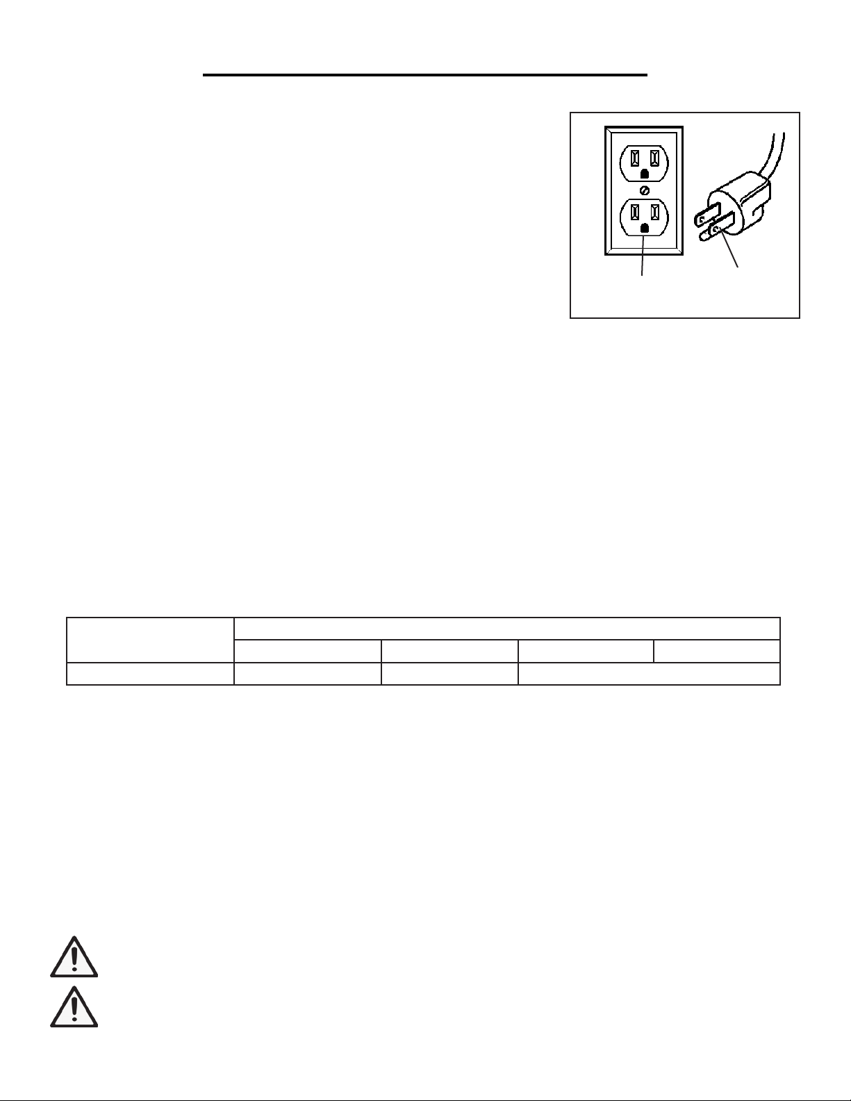
Grounded
Outlet
3-Prong
Plug
Make sure your extension cord is properly wired and in good condition. Always replace a damaged extension
cord or have it repaired by a qualified person before using it. Protect your extension cords from sharp objects,
excessive heat and damp/wet areas.
USE ONLY THREE-WIRE EXTENSION CORDS that have three-pronged plugs and outlets that accept the
tool’s plug as shown in Fig. A. Repair or replace a damaged or worn cord immediately.
Use a separate electrical circuit for your tools. This circuit must not be less than a #12 wire and should be protected with a 15 A time-delayed fuse. Before connecting the motor to the power line, make sure the switch is in the
OFF position and the electric current is rated the same as the current stamped on the motor nameplate. Running
at a lower voltage will damage the motor.
WARNING: This tool is for indoor use only. Do not expose to rain or use in damp locations.
WARNING: Do not abuse the cord. Never use the cord for carrying or pulling. Keep cord away from heat,
oil, sharp edges or moving parts. Damaged or entangled cords increase the risk of electric shock.
4
Page 5

MAINTENANCE
WARNING: To avoid accidents, make sure the power switch is in the OFF position and unplug the tool
from the electrical outlet before assembly, cleaning or performing any maintenance.
1. Before each use, inspect the general condition of the tool. Check for:
• Loose hardware,
• Misalignment or binding of moving parts,
• Damaged cord/electrical wiring,
• Cracked or broken parts, and
• Any other condition that may affect its safe operation.
2. After every use, wipe the external surfaces with a clean cloth. Do not let water enter the electrical system.
PRODUCT DISPOSAL
The tool, accessories and packaging should be sorted for recycling, instead of disposed of with household waste.
Please take them to your local recycling facility for responsible disposal and to minimize the environmental impact.
Page 6

EXPLODED VIEW & PARTS LIST
Unpack and remove all parts from the box. Check all components and organize them according to the parts list
below. If any part is damaged or missing, please contact our customer service at (800) 232-1195, M-F 8-5 CST or
email us at techsupport@wenproducts.com.
No. Part No. Description Qty.
1 WB4723-001 Front Post 2
2 WB4723-002 Back Post 2
3 WB4723-003 Rubber Foot 4
4 WB4723-004 Side Beam 3
4A WB4723-004A Side Beam with Power Strip Opening 1
5 WB4723-005 Bottom Beam 2
6 WB4723-006 Top Beam 2
7F WB4723-007F Front Drawer Bracket 1
7B WB4723-007B Back Drawer Bracket 1
8 WB4723-008 Middle Drawer Mount 1
9L WB4723-009L Left Drawer Mount 1
9R WB4723-009R Right Drawer Mount 1
10L WB4723-010L Left Drawer Panel 2
10R WB4723-010R Right Drawer Panel 2
11 WB4723-011 Front Drawer Panel 2
12 WB4723-012 Back Drawer Panel 2
13 WB4723-013 Drawer Bottom 2
14 WB4723-014 Drawer Handle 2
15L WB4723-015L Left Back Upper Post 1
15R WB4723-015R Right Back Upper Post 1
16F WB4723-016F Front Shelf Beam 1
16B WB4723-016B Back Shelf Beam 1
17L WB4723-017L Left Shelf Beam 1
17R WB4723-017R Right Shelf Beam 1
18 WB4723-018 Pegboard 1
19 WB4723-019 Bench Top 1
20 WB4723-020 Bottom Shelf 1
21 WB4723-021 Top Shelf 1
22 WB4723-022 Power Strip (not shown) 1
23 WB4723-023 Light Fixture (not shown) 1
A WB4723-024 Bolt (M4x10), Washer, Nut (not shown) 8
B WB4723-025 Bolt (M6x10), Washer, Nut (not shown) 78
C WB4723-026 Bolt (M6x16), Washer, Nut (not shown) 13
D WB4723-027 Bolt (M5x25), Washer, Nut (not shown) 12
E WB4723-028 Screw (ST4x9.5) (not shown) 4
F WB4723-029 U Bracket (not shown) 2
G WB4723-030 Bolt (M4x16) (not shown) 2
Page 7

EXPLODED VIEW & PARTS LIST
21
4A
15L
17L
18
16F
19
16B
17R
15R
4
9L
2
1
13
12
10L
7F
4
10L
10R
5
7B
8
5
(Under Part 20)
13
20
6
12
10R
9R
2
4
1
3
14
11
14
11
7
Page 8

Assembly Instructions
Read the ENTIRE IMPORTANT SAFETY INFORMATIONS section at the beginning of this document
including all text under subheadings therein before set up or use of this product.
Note: Unless stated otherwise, all connections are
made using Bolts, Washers and Nuts (B). Finger tighten
all connections until assembly is done. Assemble the
Workbench on a flat, level, and hard surface.
1. Attach Side Beams (4) to Front (1)
and Back Posts (2).
2. Attach Rubber Feet (3) to the bottom
of all 4 posts. (See Figure A.)
1
2
4
3
3
1
2
3
3
4
Figure A
3. Attach Bottom Beams (5) to the Front (1)
and Back (2) Posts. (See Figure B.)
4. Attach Side Beam (4) and Side Beam with Power
Strip Opening (4A) to the top 2 holes on Front
Posts (1) and the middle 2 holes on Back Posts (2).
Note: Side Beam with Power Strip Opening can
be attached to either the right or left side.
5. Attach Power Strip (22) to Side Beam with
Power Strip Opening using U Brackets
(F) and Screws (E). (See Figure C.)
4
4A
22
E
F
E
E
E
2
2
1
1
Figure C
6. Attach Top Beams (6) to the top 2 holes
on Front Posts (1) and the middle 2 holes
on Back Posts. (See Figure D.)
Note: Make sure the Front Top Beam (6) carries
the Warning Label and is right-side up.
6
2
Assembly Instructions
Read the ENTIRE IMPORTANT SAFETY INFORMATIONS section at the beginning of this document
including all text under subheadings therein before set up or use of this product.
Note: Unless stated otherwise, all connections are
made using Bolts, Washers and Nuts (B). Finger tighten
all connections until assembly is done. Assemble the
Workbench on a flat, level, and hard surface.
1. Attach Side Beams (4) to Front (1)
and Back Posts (2).
2. Attach Rubber Feet (3) to the bottom
of all 4 posts. (See Figure A.)
4. Attach Side Beam (4) and Side Beam with Power
Strip Opening (4A) to the top 2 holes on Front
Posts (1) and the middle 2 holes on Back Posts (2).
Note: Side Beam with Power Strip Opening can
be attached to either the right or left side.
5. Attach Power Strip (22) to Side Beam with
Power Strip Opening using U Brackets
(F) and Screws (E). (See Figure C.)
4
4A
22
E
F
E
E
E
2
2
1
1
ASSEMBLY & ADJUSTMENTS
Assembly of the work station requires two people. Get a good buddy (or a trustworthy foe) to help you.
Before assembly: Each part should have been labeled with its corresponding number/letter. Organize all the
parts according to the exploded view and parts list on page 6 & 7, so you can find the parts you need for each step.
Allocate sufficient space on a flat, level, and hard surface for assembly.
Tools required (not included): Phillips head screwdriver, medium drive, and 7mm, 8mm, and 10mm socket.
NOTE: Only finger tighten all fasteners during assembly to allow for adjustments. Level all components at the
end of the assembly, and THEN fully tighten all fasteners using the appropriate tools.
1
2
1
4
3
4
3
1
Figure A
2
3
1
3
1. Installing Bottom Side
2
Beams (1, 2, 4)
Attach the bottom side beams (4) to
the inside of the front (1) and back
posts (2), using M6x10 bolts, washers
and nuts (B). See Figure A.
2. Attaching Rubber Feet (3)
Attach the rubber feet (3) to the bottom of all 4 posts (1 & 2).
See Figure A.
3. Installing Bottom Front
& Back Beams (5)
Attach the bottom beams (5) to the
inside of the front (1) and back (2)
posts, using M6x10 bolts, washers and
nuts (B). See Figure B.
2
NOTE: All beams (4, 5) should be
mounted inside of the posts (1, 2). All
flanges on the beams should be facing upwards.
5
5
Figure B
8
Page 9

4. Attach Side Beam (4) and Side Beam with Power
Strip Opening (4A) to the top 2 holes on Front
Posts (1) and the middle 2 holes on Back Posts (2).
Note: Side Beam with Power Strip Opening can
be attached to either the right or left side.
5. Attach Power Strip (22) to Side Beam with
Power Strip Opening using U Brackets
(F) and Screws (E). (See Figure C.)
4
4A
22
E
F
E
E
E
2
2
1
1
Figure C
6. Attach Top Beams (6) to the top 2 holes
on Front Posts (1) and the middle 2 holes
on Back Posts. (See Figure D.)
Note: Make sure the Front Top Beam (6) carries
the Warning Label and is right-side up.
ASSEMBLY & ADJUSTMENTS
4
1
2
E
E
E
E
Figure C
F
22
4A
2
1
6
6
2
2
4. Installing
Upper Side Beams (4, 4A)
Attach one side beam (4) and the side
beam with power strip opening (4A)
to the top 2 holes on the front posts
(1) and middle 2 holes on the back
posts (2), using M6x10 bolts, washers
and nuts (B). See Figure C.
NOTE: The side beam with power
strip opening can be attached to
either the right or left side.
5. Attaching Power Strip (22)
Attach the power strip (22) to the side
beam power strip opening (4A), using
U brackets (F) and ST4 x 9.5 screws
(E). See Figure C.
6. Installing Upper Front &
Back Beams (6)
Attach the upper beams (6) to the
top 2 holes on front posts (1) and the
middle 2 holes on the back posts (2),
using M6x10 bolt, washer and nut (B).
See Figure D.
NOTE: All beams (4, 4A, 6) should
be mounted inside of the posts (1, 2).
All f langes on the beams should be
facing upwards.
1
1
Figure D
9
Page 10

7. Attach Front (7F) and Back (7B) Drawer
Brackets to Top Beams (6). (See Figure E.)
Figure E
8. Attach Middle Drawer Mount (8) to the Front
(7F) and Back (7B) Drawer Brackets.
9. Attach Left (9L) and Right (9R) Drawer Mounts to
Front (1) and Back (2) Posts. (See Figure F.)
11. Lay Drawer Bottom (13) down on a flat surface.
Attach Right (10R) and Left (10L) Drawer Panels
to the Front (11) and Back (12) Drawer Panels.
Repeat for second Drawer. (See Figure G.)
12. Install the Drawers, making sure the runners on
the Drawers are level with the Drawer Mounts
14
11
10R
11
10L
13
A
A
A
A
Figure G
13. Attach left and right Back Upper Posts (15)
to left and right Back Posts (2).
14. Attach Back Shelf Beam (16B) to Back Upper Posts.
15. Attach Left Shelf Beam (17L) and Right Shelf
Beam (17R) to the back Shelf Beam (16B).
16. Attach Front Shelf Beam (16F) to Left and Right
Shelf Beams (17L, 17R). (See Figure H.)
17L
15
15
16F
16B
7F
7B
7. Attach Front (7F) and Back (7B) Drawer
Brackets to Top Beams (6). (See Figure E.)
11. Lay Drawer Bottom (13) down on a flat surface.
Attach Right (10R) and Left (10L) Drawer Panels
to the Front (11) and Back (12) Drawer Panels.
Repeat for second Drawer. (See Figure G.)
12. Install the Drawers, making sure the runners on
the Drawers are level with the Drawer Mounts
14
11
10R
10L
13
12
A
A
A
A
ASSEMBLY & ADJUSTMENTS
7B
7F
Figure E
9L
1
2
8
9R
1
Figure F
7. Mounting
Drawer Brackets (7F, 7B)
Attach the front (7F) and back (7B)
drawer brackets to the outside of the
top beams (6), using M6x10 bolts,
washers and nuts (B). See Figure E.
8. Attaching Middle Drawer
Mount (8)
Attach the middle drawer mount (8)
to the front (7F) and back (7B) drawer
brackets, using M6x10 bolts, washers
and nuts (B). See Figure F.
NOTE: The open end of the drawer
mount should be facing towards the
front so the drawers can be assembled
later.
9. Attaching Left & Right
Drawer Mounts (9L, 9R)
Attach the left (9L) and right (9R)
drawer mounts to the inside of the
front (1) and back (2) posts, using
M6x10 bolts, washers and nuts (B).
See Figure F.
2
W
NOTE: The open end of the drawer
mounts should be facing towards the
front so the drawers can be assembled
later.
10. Attaching Drawer Handles
(14)
Attach one drawer handle (14) to the
front drawer panel, using M4x10 bolts,
washers and nuts (A). See Figure G on
next page.
Repeat for attaching the other handle
to the second front drawer panel.
10
Page 11

11
10R
11
10L
13
12
A
A
A
A
Figure G
to left and right Back Posts (2).
Beam (17R) to the back Shelf Beam (16B).
Shelf Beams (17L, 17R). (See Figure H.)
Attach Right (10R) and Left (10L) Drawer Panels
to the Front (11) and Back (12) Drawer Panels.
Repeat for second Drawer. (See Figure G.)
the Drawers are level with the Drawer Mounts
ASSEMBLY & ADJUSTMENTS
12
11
10L
14
A
A
A
A
13
11
10R
Figure G
11. Attaching Drawer Panels
(10L, 10R, 11, 12, 13)
Lay one drawer bottom (13) down on a
flat surface. Attach the right (10R) and
left (10L) drawer panels to the inside
of the front (11) and back (12) drawer
panels. See Figure G. Repeat for second drawer.
12. Installing Drawers
Install the drawers, making sure the runners on the drawers are level with the
drawer mounts (8, 9L, 9R). Check the
drawers’ run (you may have to swap the
drawers side to side to get a better fit).
13. Attaching
Back Upper Posts (15)
Attach the left and right back upper
posts (15) to inside of the left and right
back posts (2), at the left and right side
mounting holes (not the back mounting
holes), using M6x10 bolts, washers and
nuts (B). See Figure H.
17L
16B
16F
15
2
Figure H
15
17R
2
14. Attaching
Back Shelf Beam (16B)
Attach the back shelf beam (16B) to
the inside the back upper posts, at
the uppermost mounting holes, using
M6x10 bolts, washers and nuts (B). See
Figure H.
15. Left & Right Shelf Beam
(17L, 17R)
Attach the left shelf beam (17L) and
right shelf beam (17R) to the back shelf
beam (16B) and back upper posts (15),
using M6x10 bolts, washers and nuts
(B). See Figure H.
16. Attaching
Front Shelf Beam (16F)
Attach the front shelf beam (16F) to
the inside of the left and right shelf
beams (17L, 17R), using M6x10 bolts,
washers and nuts (B). See Figure H.
11
Page 12

17. Attach Pegboard (18) to Back Upper Posts (15)
using Bolts, Washers and Nuts (C).
(See Figure I.)
Figure I
18. Attach Bench Top (19) to Side Beams (4, 4A) and
Bottom Shelf (20) to Side Beams (4) using Bolts,
Washers and Nuts (D). (See Figure J.)
19. Attach Top Shelf (21) to the Shelf Beams (17L, 17R)
using Bolts, Washers and Nuts (D). (See Figure K.)
Figure K
D
D
D
C
C
18
C
17. Attach Pegboard (18) to Back Upper Posts (15)
using Bolts, Washers and Nuts (C).
19. Attach Top Shelf (21) to the Shelf Beams (17L, 17R)
using Bolts, Washers and Nuts (D). (See Figure K.)
Figure K
D
D
D
D
ASSEMBLY & ADJUSTMENTS
(See Figure I.)
18
17. Attaching Pegboard (18)
Attach the pegboard (18) to the back
upper posts (15), using M6x16 bolts,
C
washers, nuts (C). See Figure I.
18. Attaching Bench Top &
Bottom Shelf (19, 20)
Attach the bench top (19) to the
upper side beams (4, 4A) and the
bottom shelf (20) to the lower side
beams (4), using M5x25 bolts, washers and nuts (D). See Figure J.
C
C
Figure I
19
D
D
D
D
D
D
D
D
12
20
Figure J
Page 13

ASSEMBLY & ADJUSTMENTS
19. Attach Top Shelf (21) to the Shelf Beams (17L, 17R)
using Bolts, Washers and Nuts (D). (See Figure K.)
23
D
D
D
D
19. Attaching Top Shelf (21)
Attach the top shelf (21) to the shelf
beams (17L, 17R) using bolts, wash-
21
ers and nuts (D). See Figure K.
20. Attaching Light Fixture (23)
Attach the light fixture (23) to the
underside of the top shelf (21) using
M4x16 screws (G).
a. Insert a screw through each of the
light fixture clips.
b. Thread screws through the holes
on the underside of the top shelf.
Figure K
c. Push the light fixture up into the
clips. See Figure L.
21
21. Tighten Fasteners
Make sure all shelves are level and
check square. Then, tighten all bolts
and screws securely using the appro-
G
G
priate tools, EXCEPT the middle
drawer brackets (7F, 7B).
Figure L
Check the drawers’ run (you may
have to swap the drawers side to side
to get a better fit). Once everything
runs smoothly, tighten the middle
drawer brackets.
Check that the work station is stable.
22. Light Fixture Power Cord
Attach the light fixture power cord
to the receptacle at the end of the
fixture. It will only connect one way.
Route the cord through the hole in
the pegboard.
13
Page 14

LIMITED TWO YEAR WARRANTY
WEN Products is committed to build tools that are dependable for years. Our warranties are consistent with this
commitment and our dedication to quality.
LIMITED WARRANTY OF WEN CONSUMER POWER TOOLS PRODUCTS FOR HOME USE
GREAT LAKES TECHNOLOGIES, LLC (“Seller”) warrants to the original purchaser only, that all WEN consumer power tools will be free from defects in material or workmanship for a period of two (2) years from date of
purchase. Ninety days for all WEN products, if the tool is used for professional use.
Seller’s sole obligation and your exclusive remedy under this Limited Warranty and, to the extent permitted by
law, any warranty or condition implied by law, shall be the repair or replacement of parts, without charge, which
are defective in material or workmanship and which have not been misused, carelessly handled, or misrepaired by
persons other than Seller or Authorized Service Center. To make a claim under this Limited Warranty, you must
make sure to keep a copy of your proof of purchase that clearly defines the Date of Purchase (month and year)
and the Place of Purchase. Place of purchase must be a direct vendor of Great Lakes Technologies, LLC. Third
party vendors such as garage sales, pawn shops, resale shops, or any other secondhand merchant void the warranty
included with this product. Contact techsupport@wenproducts.com or 1-800-232-1195 to make arrangements for
repairs and transportation.
When returning a product for warranty service, the shipping charges must be prepaid by the purchaser. The product must be shipped in its original container (or an equivalent), properly packed to withstand the hazards of shipment. The product must be fully insured with a copy of the warranty card and/or the proof of purchase enclosed.
There must also be a description of the problem in order to help our repairs department diagnose and fix the issue.
Repairs will be made and the product will be returned and shipped back to the purchaser at no charge.
This limited warranty does not apply to accessory items that wear out from regular usage over time including belts,
brushes, blades, etc.
Any implied warranties shall be limited in duration to one (1) year from date of purchase. Some states in the U.S.,
Some Canadian provinces do not allow limitations on how long an implied warranty lasts, so the above limitation
may not apply to you.
In no event shall seller be liable for any incidental or consequential damages (including but not limited to liability for
loss of profits) arising from the sale or use of this product. Some states in the U.S. And some Canadian provinces
do not allow the exclusion or limitation of incidental or consequential damages, so the above limitation or exclusion
may not apply to you.
This limited warranty gives you specific legal rights, and you may also have other rights which vary from state to state
in the U.S., province to province in Canada and from country to country.
This limited warranty applies only to portable electric tools, bench power tools, outdoor power equipment and
pneumatic tools sold within the united states of America, Canada and the commonwealth of Puerto Rico. For warranty coverage within other countries, contact the wen customer support line.
14
Page 15

Page 16

THANKS FOR
REMEMBERING
 Loading...