

Page 1
3148819
3-1/4-INCH
HAND PLANER
For replacement parts visit
WENPRODUCTS.COM
Model # 6530
bit.ly/wenvideo
IMPORTANT:
Your new tool has been engineered and manufactured to WEN’s highest standards for dependability, ease
of operation, and operator safety. When properly cared for, this product will supply you years of rugged,
trouble-free performance. Pay close attention to the rules for safe operation, warnings, and cautions. If
you use your tool properly and for intended purpose, you will enjoy years of safe, reliable service.
NEED HELP? CONTACT US!
Have product questions? Need technical support?
Please feel free to contact us at:
800-232-1195
(M-F 8AM-5PM CST)
NOTICE: Please refer to wenproducts.com for the most up-to-date instruction manual.
WENPRODUCTS.COM
Page 2

TABLE OF CONTENTS
Technical Data
General Safety Rules
Specific Rules For The Planer
Electrical Information
Know Your Planer
Operation
Adjustments
Maintenance
Warranty Statement
Exploded View and Parts List
TECHNICAL DATA
Model Number:
Motor:
Speed:
Cutting Width:
Max Cutting Depth:
Max Rabbeting Depth:
Product Weight:
Contents:
2
3
4
6
7
8
12
14
15
16
6530
120 V, 60 Hz, 6A
17,000 RPM
3-1/4 in.
1/8 in.
7/10 in.
6.5 lbs
Hand Planer
Dust Bag
Rabbeting Depth Stop
Parallel Guide Fence
Replacement planer blades (Model 6530B) can be ordered in
2
two packs at wenproducts.com
Page 3

GENERAL SAFETY RULES
Safety is a combination of common sense, staying alert and knowing how your item works.
SAVE THESE SAFETY INSTRUCTIONS.
WARNING! Read all safety warnings and all instructions. Failure to follow the warnings and instruc-
tions may result in electric shock, fire and serious injury. To avoid mistakes and serious injury, do not
plug in your tool until the following steps have been read and understood.
WORK AREA SAFETY
1. Keep work area clean and well lit. Cluttered or dark areas invite accidents. Do not work on floor surfaces that are
slippery with sawdust or wax. Keep the ground clear of tripping hazard.
2. Do not operate power tools in explosive atmospheres, such as in the presence of flammable liquids, gases or dust.
Power tools create sparks which may ignite the dust or fumes.
3. Keep bystanders at a safe distance from the work area. Never allow children or pets near the tool.
ELECTRICAL SAFETY
1. Do not expose power tools to rain or wet conditions. Water entering a power tool will increase the risk of electric
shock.
2. Power tool plugs must match the outlet. Never modify the plug in any way. Modified plugs with non-matching
outlets will increase the risk of electric shock.
3. Check all power supplies periodically. Do not use defective cords. Damaged or entangled cords increase the risk
of electric shock.
4. Do not abuse the cord. Never use the cord for carrying, pulling or unplugging the power tool. Keep cord away
from heat, oil, sharp edges or moving parts.
PERSONAL SAFETY
1. Stay alert. Watch what you are doing and use common sense when operating a power tool. Do not use a power
tool while you are tired or under the influence of drugs, alcohol or medication. A moment of inattention while operating power tools may result in serious personal injury.
2. Do not wear loose clothing, gloves, neckties, or jewelry (rings, watches, etc.) when operating the tool. Inappropriate clothing and items can get caught in moving parts and draw you in. Always wear non-slip footwear and tie back
long hair.
3. Use personal protective equipment. Always wear safety goggles at all times that comply with ANSI Z87.1. Use ear
protection such as plugs or muffs during extended periods of operation. Wear work gloves to protect your hands.
Wear a face mask or dust mask to fight the dust.
4. Keep proper footing and balance at all times and do not overreach when operating the power tool.
WARNING: Dust generated from certain materials can be hazardous to your health. Always operate
the tool in a well-ventilated area and wear dust mask. Use dust collection systems when processing
wood and plastics. Dust extractors or dust bags must not be connected when processing metals.
3
Page 4

GENERAL SAFETY RULES
POWER TOOL USE AND CARE
1. Avoid accidental start-ups. Make sure the power switch is in the OFF position before connecting the plug to a
power source or carrying the tool.
2. Check power tool for damaged parts. Check for misalignment of moving parts, jamming, breakage, improper
mounting, or any other conditions that may affect the tool’s operation. Do not use the power tool if the switch does
not turn ON/OFF. Any part that is damaged should be properly repaired or replaced before use.
3. Do not force the tool to do a job for which it was not designed. Use the correct power tool and accessories and
follow the instructions for your application to prevent hazardous situations.
4. Remove adjustment tools. Always make sure all adjustment tools or wrenches are removed from the tool before
turning on the power tool.
5. Keep guards in place and in working order before operating the tool. All protection and safety devices must be
in place after completing repair and maintenance procedures
6. Never leave a running tool unattended. Do not leave the tool until it has come to a complete stop.
POWER TOOL MAINTENANCE
1. Always disconnect the power cord plug from the electrical outlet when making adjustments, changing parts, or
storing power tools. Such preventive safety measures reduce the risk of starting the power tool accidentally.
2. Maintain power tools properly. Safely store power tools out of the reach of children. Always keep tools clean and
in good working order. Follow instructions for lubricating and changing accessories.
3. Only have your power tool serviced by a qualified repair person using only identical replacement parts. Use of
any other part can cause personal injury and damage to the tool.
SPECIFIC RULES FOR THE PLANER
WARNING: To prevent serious injury, do not operate this tool until the entire manual and all warnings
have been read and understood.
WORKPIECE SAFETY
1. Secure the workpiece to a stable platform using clamps or another practical method. Never hold it in your hand
or across your legs. Unstable support could result in a loss of control and personal injury.
2. Small workpieces must be adequately secured so that the rotating planer blades don’t pick them up during the
forward motion of the planer.
3. Check the workpiece for nails and other foreign objects. If there are nails, either remove them or set them well
below the intended finished surface. Any article that encounters planer blades may be forcibly ejected from planer
creating risk of injury.
4
Page 5

SPECIFIC RULES FOR THE PLANER
OPERATION SAFETY
1. Always use ANSI Z87.1 approved safety glasses. Wear hearing protection to prevent hearing damage during operation. Use face mask or dust mask if cutting operation is dusty.
2. Keep handles and hands dry, clean and free from oil and grease. Slippery surfaces can cause you to lose control
of the power tool.
3. Always hold the planer firmly with both hands for maximum control.
4. Only hold the power tool by insulated gripping surfaces in case the cutter contacts its own cord. Cutting a “live”
wire may make exposed metal parts of the tool “live” and could give the operator an electric shock.
5. Always start the planer before the blade is in contact with the workpiece. Let the blade reach full speed before
using the tool. The planer can vibrate and possibly kickback if the cutting speed is too slow.
6. Do not plane end grain, as the wood could splinter or possibly explode. Always plane along the grain direction of
the wood. Never plane against the grain direction.
7. Never pull the planer backwards over the workpiece. Loss of control may occur.
8. Do not put fingers or any objects into the chip extraction port.
9. Remove the plug from power source before removing chips. Do not clean out chips while the tool is running.
Contact with the blade drum will cause injury as the blades are hidden from view and you may be cut if the blade
is contacted.
10. Wait for the cutter to stop before setting the tool down. An exposed rotating cutter may engage the surface, leading to possible loss of control and serious injury.
MAINTENANCE SAFETY
1. Unplug the planer before making adjustments or changing accessories. Accidental start-ups may occur if the
planer is plugged in during an accessory change.
2. Planer blades are sharp. Wear protective work gloves when removing/installing blades or turning the blade drum.
3. After changing blades, rotate the blade drum to make sure the blades don’t hit any part of the blade head housing
and that the blade locking screws are tight. Loose or misaligned blades have the potential to damage the tool and
cause possible injury.
4. Develop a periodic maintenance schedule for your tool. When cleaning be careful not to disassemble any portion of the tool. Internal wires may be misplaced or pinched and safety guard return springs may be improperly
mounted.
5. Certain cleaning agents such as gasoline, carbon tetrachloride, ammonia, etc. may damage plastic parts.
5
Page 6

ELECTRICAL INFORMATION
GROUNDING INSTRUCTIONS
IN THE EVENT OF A MALFUNCTION OR BREAKDOWN, grounding provides the path of least resistance
for an electric current and reduces the risk of electric shock. This tool is equipped with an electric cord that has an
equipment grounding conductor and a grounding plug. The plug MUST be plugged into a matching outlet that is
properly installed and grounded in accordance with ALL local codes and ordinances.
DO NOT MODIFY THE PLUG PROVIDED. If it will not fit the outlet, have the proper outlet installed by a
licensed electrician.
REPAIR OR REPLACE a damaged or worn cord immediately.
IMPROPER CONNECTION of the equipment grounding conductor can result in electric shock. The conductor with the green insulation (with or without yellow stripes) is the equipment grounding conductor. If repair or
replacement of the electric cord or plug is necessary, DO NOT connect the equipment grounding conductor to a
live terminal.
CHECK with a licensed electrician or service personnel if you do not completely understand the grounding instructions or whether the tool is properly grounded.
CAUTION: In all cases, make certain the outlet in question is properly grounded. If you are not sure, have a licensed electrician check the outlet.
WARNING: This tool is for indoor use only. Do not expose to rain or use in damp locations.
GUIDELINES AND RECOMMENDATIONS FOR EXTENSION CORDS
When using an extension cord, be sure to use one heavy enough to carry the current your product will draw. An
undersized cord will cause a drop in line voltage resulting in loss of power and overheating. The table below shows
the correct size to be used according to cord length and nameplate ampere rating. When in doubt, use a heavier
cord. The smaller the gauge number, the heavier the cord.
AMPERAGE
6A 18 gauge 16 gauge 14 gauge 12 gauge
MAKE SURE YOUR EXTENSION CORD IS PROPERLY WIRED AND IN GOOD CONDITION. Always
replace a damaged extension cord or have it repaired by a qualified person before using it.
PROTECT YOUR EXTENSION CORDS from sharp objects, excessive heat and damp/wet areas.
REQUIRED GAUGE FOR EXTENSION CORDS
25 ft. 50 ft. 100 ft. 150 ft.
Use a separate electrical circuit for your tools. This circuit must not be less than a #12 wire and should be protected
with a 15A time-delayed fuse. Before connecting the motor to the power line, make sure the switch is in the OFF
position and the electric current is rated the same as the current stamped on the motor nameplate. Running at a
lower voltage will damage the motor.
WARNING: This tool must be grounded while in use to protect the operator from electric shock.
6
Page 7
KNOW YOUR PLANER
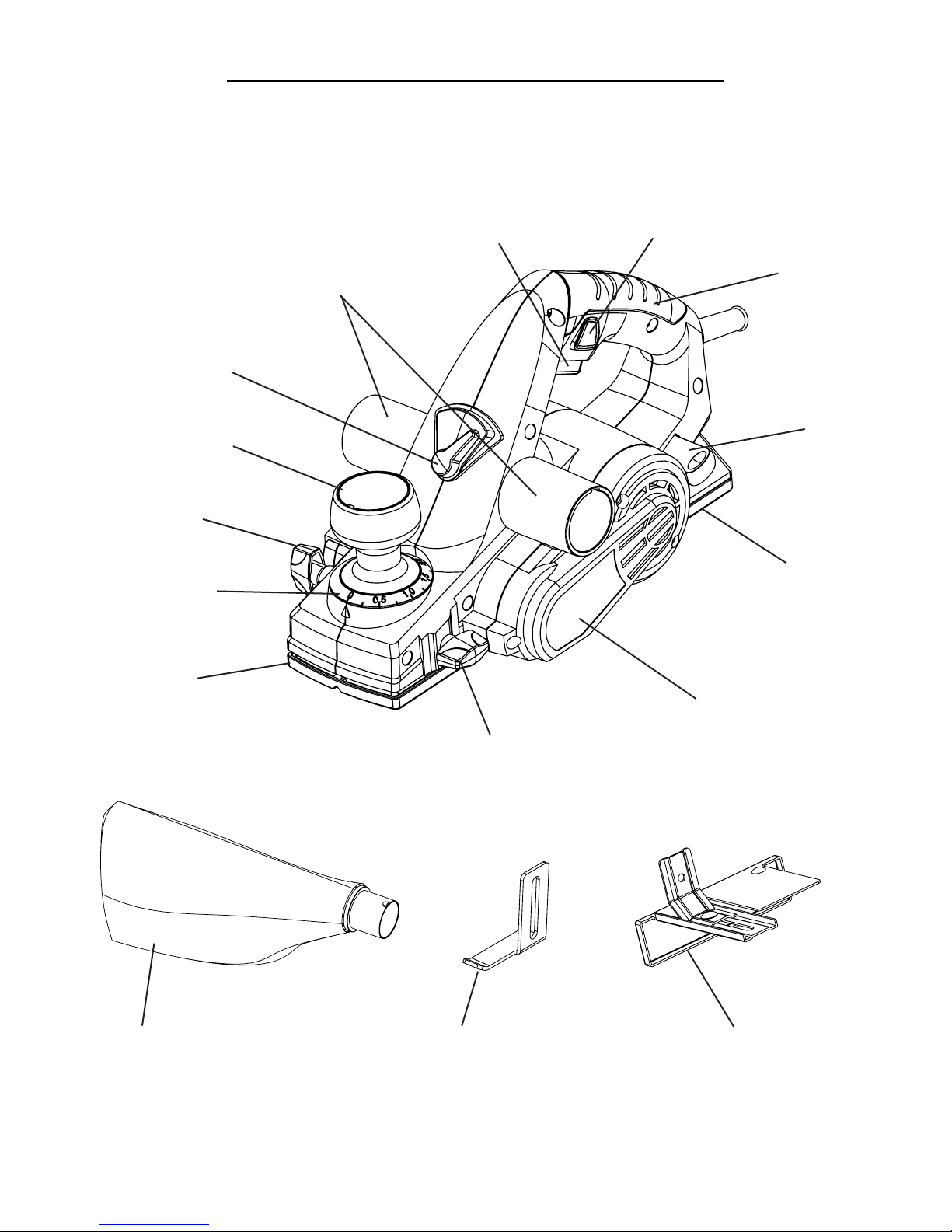
Carefully unpack the hand planer from the box. Check all components and compare against the graph below.
If any part is damaged or missing, please contact our customer service at (800) 232-1195, M-F 8-5 CST or email
Chip Extraction
Guide Switch
Depth Adjustment
Knob
Rabbeting Lock
Knob
Depth Adjustment
Gauge
Chip Extraction
Port
ON/OFF
Switch
Trigger
Lock
Handle
Blade
Wrench
Fixed Rear
Shoe
Adjustable
Front Shoe
Parallel Guide
Lock Knob
Dust Bag Parallel Guide FenceRabbeting Depth Stop
Drive Belt
Cover
7
Page 8
OPERATION
WARNING: To prevent serious injury, make sure all the instructions have been read and understood
before operating this tool. Before plugging the machine into the power supply, always check that the trigger switch and trigger lock work properly.
USING THE SAFETY KICKSTAND
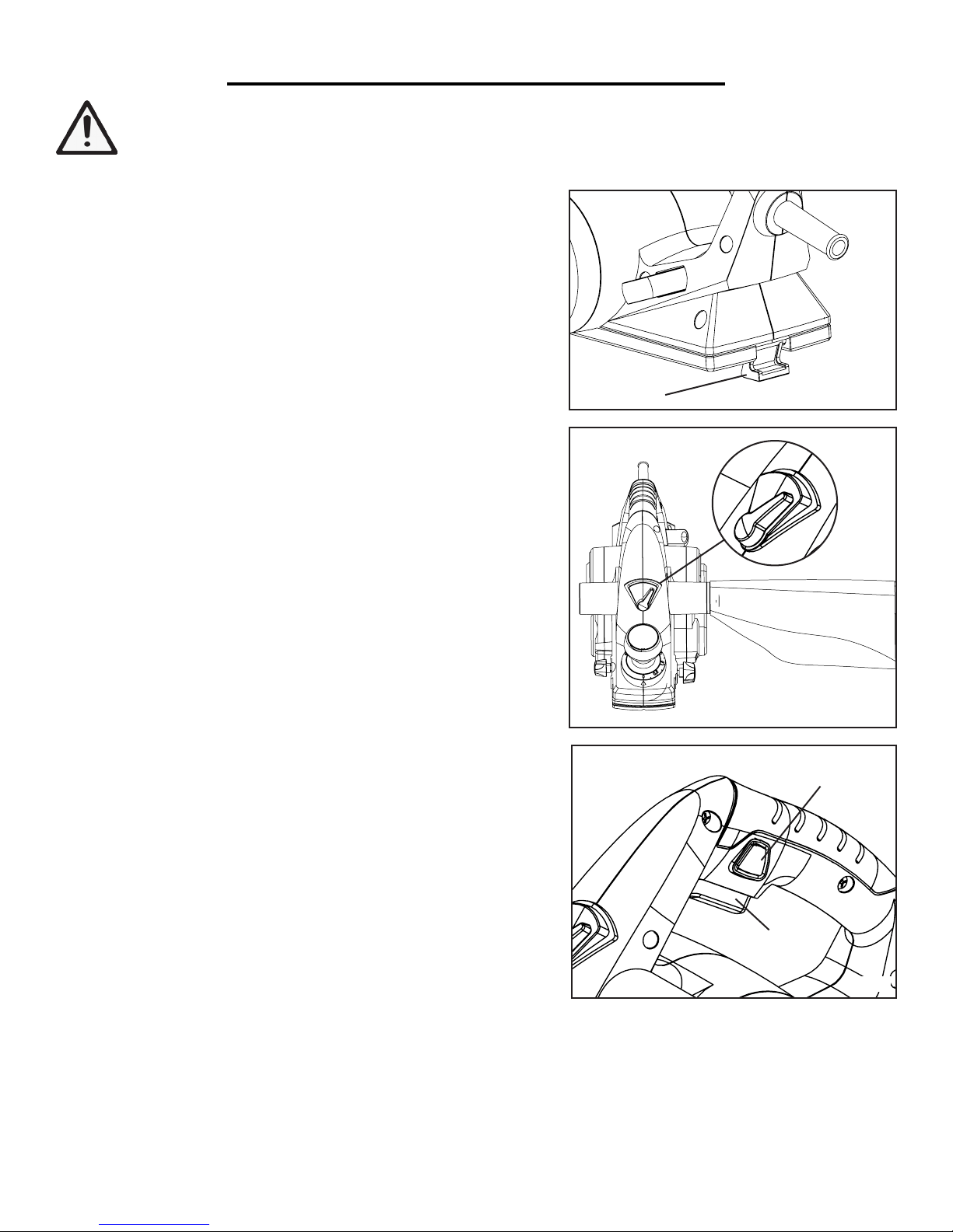
The safety kickstand (Fig. B - 1) on the back of the planer swings
down to help keep the blade from coming into contact with the
work surface when the planer is not in use.
The kickstand is designed to swing up and out of the way by it itself
when the back of the planer crosses the leading edge of the workpiece.
CONNECTING THE CHIP EXTRACTION PORT
The wood shavings can be set to flow from either side of the tool to
suit the task at hand. Set the extraction guide switch (Fig. C) to point
towards the extraction port that you wish the chips to flow towards.
If desired, attach the dust bag by sliding the nozzle onto the appropriate chip extraction port. For efficient operation, empty the
dust bag when it is no more than half full, allowing for better airflow
through the bag.
You can also connect your planer to a suitable dust extraction system through the extraction port. Hose adaptors (not included) may
be needed depending on the size of your dust hose.
WARNING: Shavings may jam in the dust extraction port when
cutting damp wood. Never stick your finger into the dust extraction
port. Clean out the shavings with a stick, but only when the cutter
has stopped running and the tool has been unplugged from the
power source.
SWITCHING ON AND OFF
The tool is equipped with a trigger lock (Fig. D - 1) to avoid unintentional start-ups.
1
Fig. B
Fig. C
1
1. To turn the planer on, press the trigger lock (Fig. D - 1) and then
squeeze the trigger switch (Fig. D - 2).
2. To switch off, release the trigger switch.
8
2
Fig. D
Page 9
OPERATION
ADJUSTING THE CUTTING DEPTH
The cutting depth of a planer is determined by the height difference
between the adjustable front shoe and the cutting edge of the blade.
The depth adjustment knob extracts the front shoe to adjust how
much blade is exposed, which determines the amount of material
that will be removed. To adjust the cutting depth:
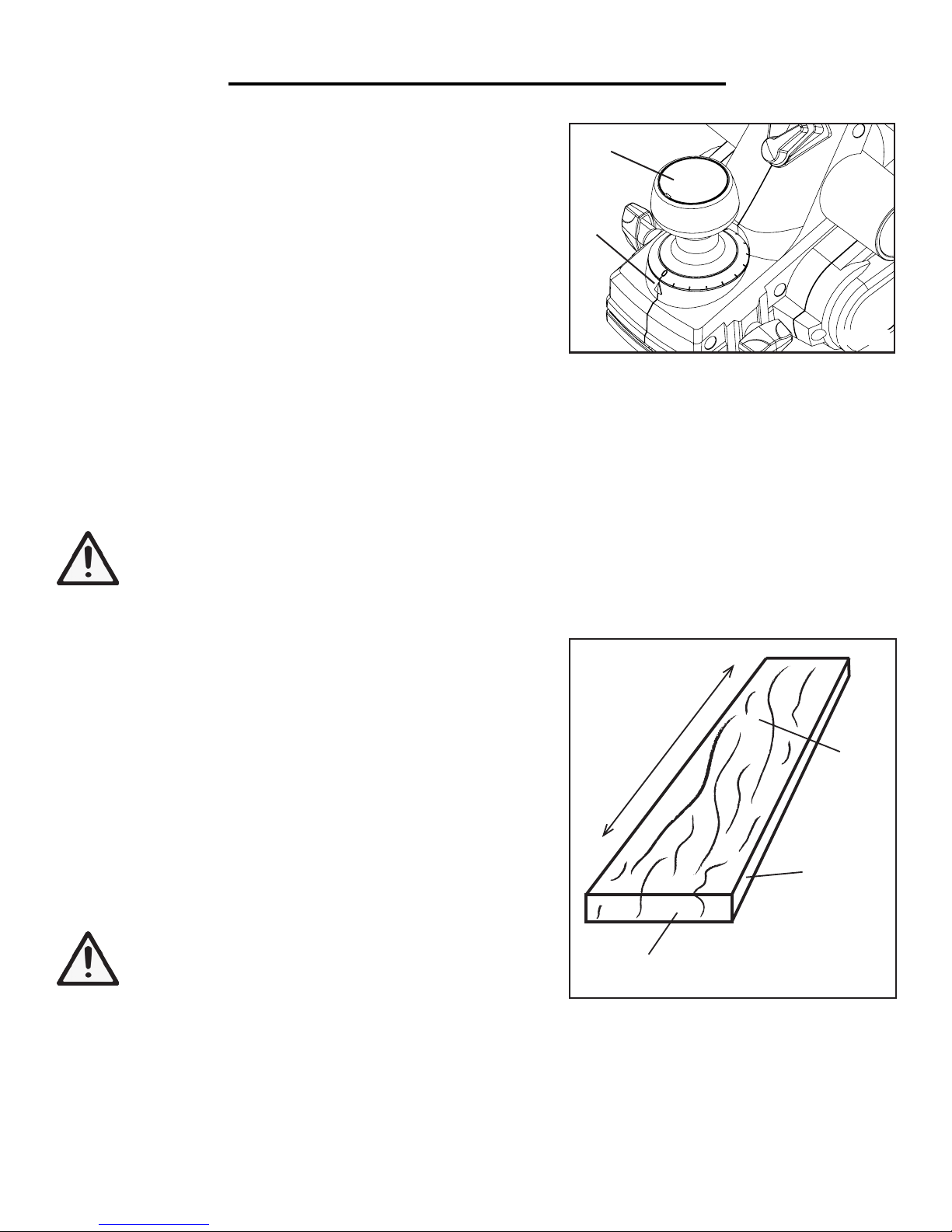
Rotate the depth adjustment knob (Fig. E - 1) until the indicator
arrow (Fig. E - 2) aligns with the desired cutting depth on the depth
gauge. Turn the depth adjustment knob clockwise for a deeper cut
and counter-clockwise for a shallower cut.
NOTE: The minimum cutting increment is 1/128 inch (0.2 mm). The maximum cutting depth of the planer is
1/8 inch. However, the more material you attempt to take off with each pass, the less even the final board will be.
The appropriate cutting depth depends on the material of your workpiece. For optimum planing performance, the
maximum cutting depth should be 1/64 of an inch per pass. Make multiple progressive cuts, removing less than 1/64
inch per pass to achieve the total cutting depth. To accurately determine the depth of cut, plane a similar piece of
scrap material and adjust the settings accordingly.
1
2
Fig. E
CAUTION: Always ensure that the number on the depth gauge is at the “0” position when the tool is
not in use. However, even at “0”, a slightly protrusive blade could still make contact depending on how
the blade was installed. Engage the safety kickstand to prevent the blade from contacting the workpiece.
THE DO’S AND DONT’S OF GRAIN DIRECTION
It is important that the planer should always be cutting in the same
direction as the grain of the wood (Fig. F). There are six sides to every board: two face grains, two side/edge grains, and two end grains.
You can plane along the direction of the grain with the face grain or
side/edge grain facing upwards, but never plane with the end grain
side facing upwards. Otherwise, the board has a chance of splintering and exploding inside of the planer, which could cause serious
injury and damage.
When planing the face and side/edge grain, always plane in the direction of the grain. Do not plane perpendicular to the grain, otherwise the board also has a chance of splintering and exploding.
WARNING: Never plane against the grain direction of
the wood. Do not plane end grain, as the wood could
splinter or possibly explode.
Direction of Grain
End
Grain
Face
Grain
Side/Edge
Grain
Fig. F
DETERMINING THE FEED RATE
The proper feed rate will depend on the type of material being cut and the depth of the cut. Moving the planer too
fast may cause a poor quality of cut and can damage the blades or the motor; moving the machine too slowly may
burn or mar the cut. Practice first on a scrap piece of material to gauge the correct feed rate and cutting dimensions.
9
Page 10

OPERATION
WARNING: Wear safety goggles at all times that comply with ANSI Z87.1. Use ear protection such as
plugs or muffs during extended periods of operation. Wear work gloves to protect your hands. Wear a
face mask or dust mask to fight the dust.
OPERATING YOUR PLANER
1. Secure the workpiece to a stable platform. Make sure that the surface to be planed is face grain or side grain. Do
not plane end grain, as the wood could splinter or possibly explode (see page 9 “The Do’s and Dont’s of Grain
Direction).
2. Hold the planer firmly with both hands. Rest the front shoe flat on the workpiece surface, ensuring that the blades
do not make contact with the workpiece.
3. Switch the tool ON and wait for the blades to reach full speed.
4. Move the tool gently forward along the grain of the wood. Apply pressure on the front of the tool at the beginning
of planing, and at the rear of the tool towards the end of the planing stroke.
5. Push the planer beyond the edge of the workpiece without tilting it downwards. Turn off the planer and wait for
the cutter to stop before setting the tool down.
NOTE: The feed rate and the depth of cutting determine the quality of the finish. Increase the depth of cut for
rough cutting and reduce the depth of the cut to achieve a smoother finish.
CAUTION: The motor may stall if improperly used or overloaded. Reduce the pressure (feed rate) or
the depth of cut to prevent possible damage to the tool if the motor labors.
MAKING A CHAMFER CUT
The V-groove in the front shoe allows for quick and easy chamfers, creating a creating a sloping edge along the
corner of your workpiece.
1. Make sure that the workpiece is secured to a stable platform.
2. Hold the planer firmly with both hands. Align the V-groove in
the front shoe of the planer with the corner edge of the workpiece
(Fig. G). Be sure the blades are not touching the work. Place weight
on the depth adjustment knob so that the V-groove is absolutely flat
on the edge to be beveled.
45 °
3. Switch the tool ON and wait for the blades to reach full speed.
4. Push the planer forward along the grain of the wood with steady
pressure on the front shoe.
Fig. G
5. Push the planer beyond the edge of the workpiece without tilting
it downwards. Turn off the planer and wait for the cutter to stop
before setting the tool down.
10
Page 11
OPERATION
WARNING: To avoid injury from accidental startups, always ensure that the tool is switched OFF and
unplugged from the power supply before making any adjustments to the planer.
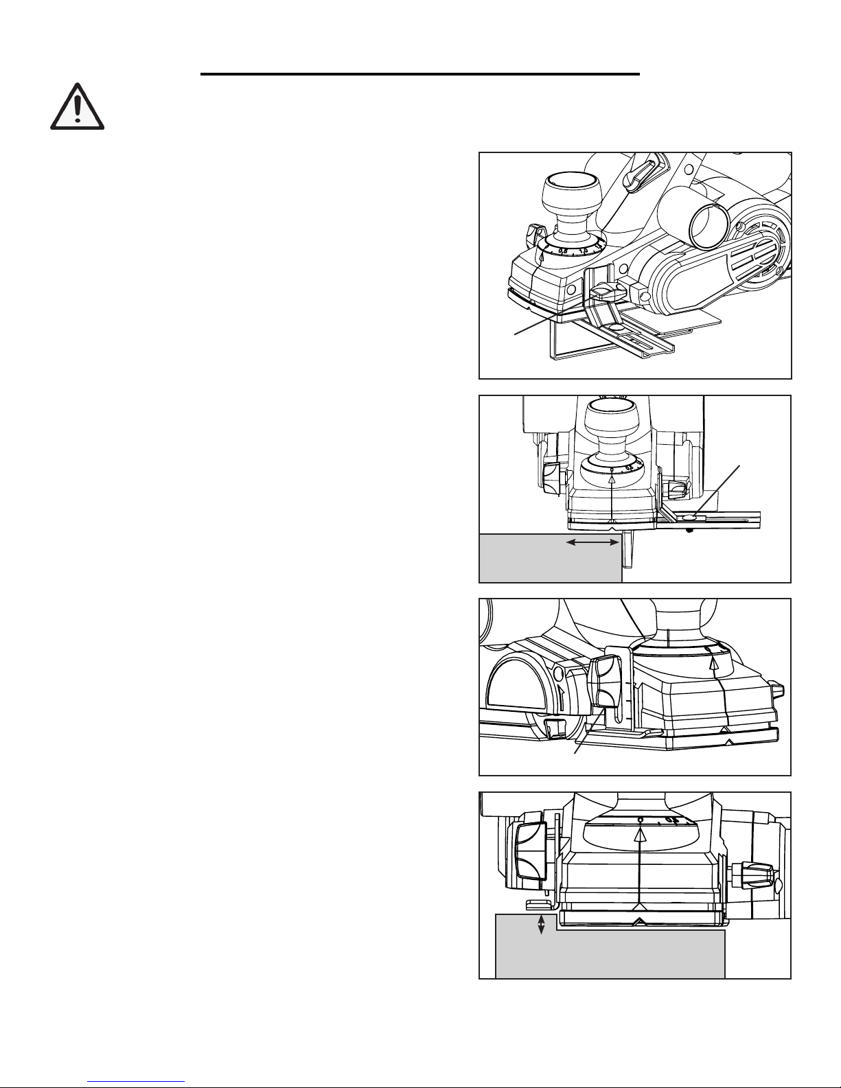
USING THE PARALLEL GUIDE FENCE
The parallel guide fence ensures that the planer travels parallel
to the edge of the wood , providing a straight cut at your desired
cutting width. This feature is helpful for planing door edges,
wood trim and boards. To attach the parallel guide fence:
1. Disconnect the planer from the power source.
2. Attach the parallel guide fence to the left-hand side of the
planer using the lock knob (Fig. H - 1).
1
3. Loosen the wing nut (Fig. I - 1) on the parallel guide fence and
slide the fence to set the desired cutting width indicated by the
width gauge. Retighten the wing nut.
NOTE: To ensure a square cut, measure the front and back of
the fence and use a square to make sure the guide is set straight.
4. Rest the front shoe flat on the workpiece surface and position
the fence firmly against the edge of the workpiece (Fig. I). Follow instructions on page 10 “Operating your Planer” to perform
your cut.
USING THE RABBETING DEPTH GUIDE
The rabbeting depth guide can be adjusted anywhere from 0 to
7/10 of an inch above the base of the planer. To attach the rabbeting depth guide:
1. Disconnect the planer from the power source.
2. Attach the rabbeting depth gauge to the right-hand side of the
planer using the lock knob (Fig. J - 1). Position the rabbeting
depth gauge to the desired height against the depth indication
mark on the side housing. Tighten the lock knob.
Cutting
Width
1
Fig. H
1
Fig. I
Fig. J
3. If desired, use the parallel guide fence in conjuction with the
rabbeting depth guide to create a straight rabbeting cut.
4. Make multiple progressive cuts to achieve the total cutting
depth. The required rabbeting depth is achieved when the depth
gauge is flush with the unplaned section of the workpiece to the
right-hand side of the tool (Fig. K).
NOTE: The rabbeting depth gauge allows only approximate depth settings. If it is necessary to rabbet to a precise
depth, plane a scrap piece of wood, measure the rabbeted depth, and adjust the setting as necessary.
Rabbeting
Depth
Fig. K
11
11
Page 12
ADJUSTMENTS
WARNING: To avoid injury from accidental startups, always ensure that the tool is switched OFF and
unplugged from the power supply before making adjustments or installing or removing blades.
REMOVING OR INSTALLING PLANER BLADES
WARNING: Planer blades are sharp and fragile. Wear protective gloves to protect your hands. Handle
the blades carefully to avoid personal injury or damage to the blades.
WARNING: Do not attempt to sharpen or use resharpened blades of any kind. Use only blades designated for use with this model. Other blades may not clamp securely in the blade holder, causing vibration
and a decrease in performance.
Condition of blades will affect the precision of cuts. Observe the quality of the cut that the planer produces to check
the condition of the blades. Dull blades will tear wood fibers and produce fuzzy surfaces. Raised grain will occur on
the wood when the cutting blades are dull or nicked.
NOTE: Blades on this planer are reversible and should always be reversed or replaced as a matched set. Unbalanced blades can cause vibration and poor planing action while shortening the life of the blade and the tool. Keeping
a spare set of blades on hand is recommended. Replacement blades (Model 6530B) can be ordered in two packs
at wenproducts.com.
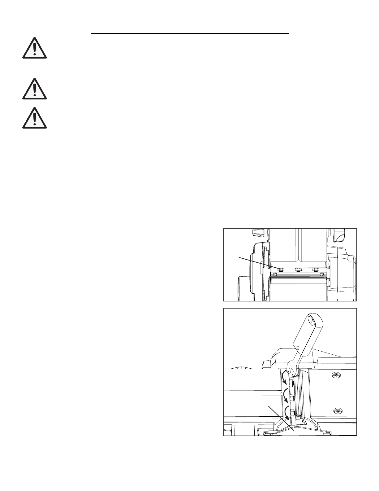
1. Disconnect the planer from the power source.
2. Put the planer on a secure work surface and turn it upside
down. Carefully rotate the blade drum to expose the clamping
screws (Fig. L - 1).
3. Loosen the three clamping screws using the onboard blade
wrench located on the back of the planer. Rotate the blade wrench
towards the blade guard side to loosen the screw (Fig. M).
CAUTION: The blade drum can rotate as you’re doing this so
be careful not to contact the blade with your hand. If the screw is
difficult to loosen, try tightening it a little and then loosen it.
4. Hold the blade drum in place and carefully slide the blade (Fig.
N - 1) out towards the blade guard side. You can also use a wooden block to push the blade out of the blade drum.
5. Clean out all chips or foreign matter adhering to the blade drum
and the blade using a soft brush or compressed air.
6. Each planer blade has two cutting edges and may be reversed
when one of the cutting edges becomes dull or chipped.
1
Fig. L
Blade Guard
• If one edge is dull, reverse the blade.
• If both edges are dull, remove the old blade and replace it with a new one.
12
Fig. M
(Continued on the next page)
Page 13
ADJUSTMENTS
WARNING: To avoid injury from accidental startups, always ensure that the tool is switched OFF and
unplugged from the power supply before making adjustments or installing or removing blades.
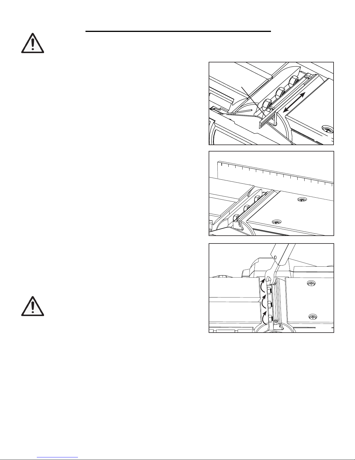
7. Slide the blade with the good side up into the blade retainer
of the blade drum (Fig. N). NOTE: The flat side of the blade
should be facing the front of the planer and the ridged side of the
blade should be facing the back of the planer.
8. To ensure an even cut, the blade should align with the outside
edge of the front and rear shoes. Place a straight edge along the
outside edge of the front and rear shoe (Fig. O). Slide the planer
blade to just contact the straight edge so that it is in line with the
outside edge of the shoes.
9. The blades must be mounted so that the cutting edge is absolutely level (parallel to the surface of the rear shoe). Check that
both ends of the blade protrude out evenly from the blade retainer of the blade drum.
1
Fig. N
NOTE: The planed surface will end up rough and uneven if
blades are not set properly or securely.
10. Tighten the clamping screws using the blade wrench, ensuring
that all three screws are tightened evenly (Fig P).
11. Repeat steps 2 - 10 for the installing/changing the second
blade. It is important to reverse or replace the two blades at the
same time so they are balanced with one another. Both blades
should be set to the same cutting level and alignment, otherwise
the planed surface will be rough and uneven.
CAUTION: Tighten all clamping screws carefully
when attaching the blades to the planer. A loose clamping screw can be extremely dangerous. Check regularly
to make sure that all six clamping screws are tightened securely.
Fig. O
Fig. P
13
Page 14
MAINTENANCE
WARNING: To prevent serious injury from accidental operation, make sure that the planer is turned off
and unplugged from power source before installation, cleaning and maintenance operations.
WARNING: Preventive maintenance performed by unauthorized personnel may result in misplacing of
internal wires and components, possibly causing a serious hazard. We recommend that all tool service be
performed by a WEN Service Center.
CLEANING
Keep the planer clean of any wood chips, dust, dirt or debris. Ventilation openings and switch levers must be kept
clean and free of foreign matter. The tool may be cleaned most effectively with compressed dry air. Always wear
safety goggles when cleaning tools with compressed air. Do not attempt to clean these components by inserting
pointed objects through openings.
WARNING: Certain cleaning agents and solvents damage plastic parts. Some of these are: gasoline,
carbon tetrachloride, chlorinated cleaning solvents, ammonia and household detergents that contain ammonia.
CARBON BRUSHES
To maintain maximum efficiency of the motor, we recommend
changing the carbon brushes every 60 hours of operation. Replacement carbon brushes (Model 6530-038) are available at
wenproducts.com. Only genuine WEN replacement brushes designed specifically for your tool should be used. To inspect or
replace the carbon brushes:
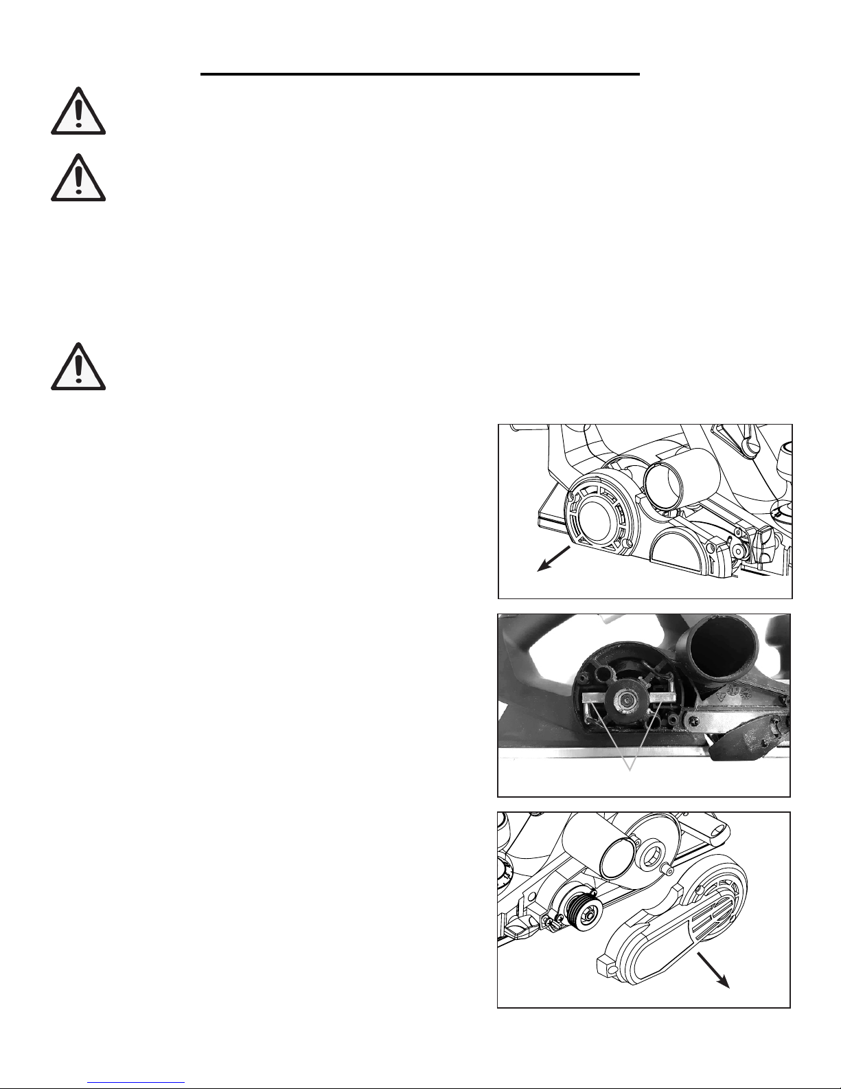
1. Unscrew and open the motor cover on the right (Fig. Q).
2. Carefully take out the two carbon brushes (Fig. R - 1) using pliers and replace with new brushes.
3. Replace the motor cover and secure with screws.
TOOL LUBRICATION
Your tool has been properly lubricated and is ready to use. It is
recommended that tools with gears be regreased with a special
gear lubricant at every carbon brush change.
DRIVE BELT
Inspect the drive belt every 60 hours of use. If the drive belt
shows signs of drying out, cracking, tearing or improper tracking,
it should be replaced. To replace the drive belt, unscrew and open
the belt cover on the left (Fig. S). Replace with identical replacement belt and close the drive belt cover.
BEARINGS
Bearings that become noisy (due to heavy load or abrasive material cutting) should be replaced by a qualified technician as soon
as possible to avoid overheating or motor failure.
Fig. Q
1
Fig. R
Fig. S
14
Page 15

LIMITED TWO YEAR WARRANTY
WEN Products is committed to building tools that are dependable for years. Our warranties are consistent with
this commitment and our dedication to quality.
LIMITED WARRANTY OF WEN CONSUMER POWER TOOLS PRODUCTS FOR HOME USE
GREAT LAKES TECHNOLOGIES, LLC (“Seller”) warrants to the original purchaser only, that all WEN consumer power tools will be free from defects in material or workmanship for a period of two (2) years from date of
purchase. Ninety days for all WEN products, if the tool is used for professional use.
SELLER’S SOLE OBLIGATION AND YOUR EXCLUSIVE REMEDY under this Limited Warranty and, to
the extent permitted by law, any warranty or condition implied by law, shall be the repair or replacement of parts,
without charge, which are defective in material or workmanship and which have not been misused, carelessly
handled, or misrepaired by persons other than Seller or Authorized Service Center. To make a claim under this
Limited Warranty, you must make sure to keep a copy of your proof of purchase that clearly defines the Date of
Purchase (month and year) and the Place of Purchase. Place of purchase must be a direct vendor of Great Lakes
Technologies, LLC. Third party vendors such as garage sales, pawn shops, resale shops, or any other secondhand
merchant void the warranty included with this product. Contact [email protected] or 1-800-2321195 to make arrangements for repairs and transportation.
When returning a product for warranty service, the shipping charges must be prepaid by the purchaser. The product must be shipped in its original container (or an equivalent), properly packed to withstand the hazards of shipment. The product must be fully insured with a copy of the warranty card and/or the proof of purchase enclosed.
There must also be a description of the problem in order to help our repairs department diagnose and fix the
issue. Repairs will be made and the product will be returned and shipped back to the purchaser at no charge.
THIS LIMITED WARRANTY DOES NOT APPLY TO ACCESSORY ITEMS THAT WEAR OUT FROM
REGULAR USAGE OVER TIME INCLUDING BELTS, BRUSHES, BLADES, ETC.
ANY IMPLIED WARRANTIES SHALL BE LIMITED IN DURATION TO TWO (2) YEARS FROM
DATE OF PURCHASE. SOME STATES IN THE U.S., SOME CANADIAN PROVINCES DO NOT ALLOW LIMITATIONS ON HOW LONG AN IMPLIED WARRANTY LASTS, SO THE ABOVE LIMITATION MAY NOT APPLY TO YOU.
IN NO EVENT SHALL SELLER BE LIABLE FOR ANY INCIDENTAL OR CONSEQUENTIAL DAMAGES (INCLUDING BUT NOT LIMITED TO LIABILITY FOR LOSS OF PROFITS) ARISING FROM
THE SALE OR USE OF THIS PRODUCT. SOME STATES IN THE U.S. AND SOME CANADIAN
PROVINCES DO NOT ALLOW THE EXCLUSION OR LIMITATION OF INCIDENTAL OR CONSEQUENTIAL DAMAGES, SO THE ABOVE LIMITATION OR EXCLUSION MAY NOT APPLY TO
YOU.
THIS LIMITED WARRANTY GIVES YOU SPECIFIC LEGAL RIGHTS, AND YOU MAY ALSO HAVE
OTHER RIGHTS WHICH VARY FROM STATE TO STATE IN THE U.S., PROVINCE TO PROVINCE
IN CANADA AND FROM COUNTRY TO COUNTRY.
THIS LIMITED WARRANTY APPLIES ONLY TO PORTABLE ELECTRIC TOOLS, BENCH POWER TOOLS, OUTDOOR POWER EQUIPMENT AND PNEUMATIC TOOLS SOLD WITHIN THE
UNITED STATES OF AMERICA, CANADA AND THE COMMONWEALTH OF PUERTO RICO. FOR
WARRANTY COVERAGE WITHIN OTHER COUNTRIES, CONTACT THE WEN CUSTOMER SUPPORT LINE.
15
Page 16
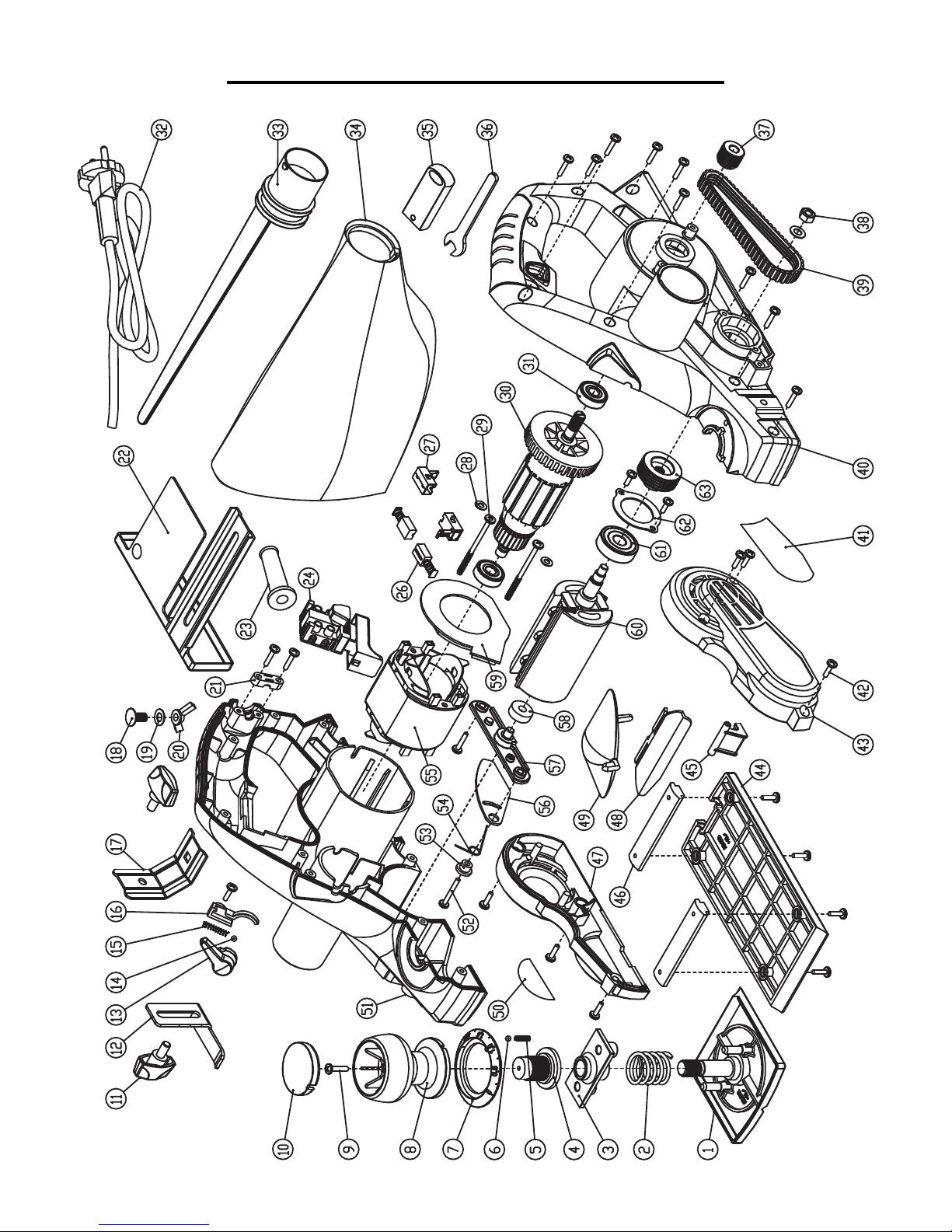
EXPLODED VIEW AND PARTS LIST
16
Page 17

EXPLODED VIEW AND PARTS LIST
No. Part No. Description Qty.
1 6530-013 Front Shoe 1
2 6530-014 Adjust Spring 1
3 6530-015 Adjust Support 1
4 6530-008 Regulative Shaft 1
5 6530-012 Front Shoe Ball Spring 1
6 6530-010 Ball Ø3.5 1
7 6530-009B Graduation Ring 1
8 6530-007 Adjust Knob 1
9 6530-004 Screw ST4x16 13
10 6530-006B Knob Cover 1
11 6530-065B Lock Knob 2
12 6530-062 Depth Scale 1
13 6530-057B Extraction Guide Knob 1
14 6530-011 Ball Ø4 1
15 6530-055
Extraction Guide
Ball Spring
1
No. Part No. Description Qty.
33 6530-067 Connecting Hose 1
34 6530-068 Dust Bag 1
35 6530-064B Wrench Box 1
36 6530-063 Blade Wrench 40Mm 1
37 6530-032 Driving Wheel 1
38 6530-029 Nut M6 1
39 6530-016 Belt 1
40 6530-030 Left Housing 1
41 6530-041B Logo Sticker 1
42 6530-042 Screw ST4x13 13
43 6530-017 Belt Cover 1
44 6530-051 Rear Shoe 1
45 6530-046B Tool Park Rest 1
46 6530-052 Panel Strip 2
47 6530-002 Motor Cover 1
48 6530-048 Adjusting Plate Knob 1
16 6530-056 Spring Seat 1
17 6530-059 Fixation Frame 1
18 6530-060 Bolt M6x12 1
19 6530-028 Washer 6 2
20 6530-058 Thumb Nut M6 1
21 6530-040 Cable Clamp 1
22 6530-061 Rabbeting Depth Stop 1
23 6530-053 Cable Bushing 1
24 6530-044B ON/OFF Switch 1
26 6530-038 Carbon Brush 2
27 6530-039 Brush Lining 2
28 6530-036 Washer 4 2
29 6530-035 Screw ST4x55 2
30 6530-034 Rotor 1
31 6530-033 Rotor Ball Bearing 2
32 6530-066 Power Cord 1
49 6530-054 Adjusting Plate 1
50 6530-001 Nameplate 1
51 6530-005 Right Housing 1
52 6530-070 Screw ST4x25 1
53 6530-018 Lock Sleeve 1
54 6530-019 Torsional Spring 1
55 6530-037 Stator 1
56 6530-020 Blade Guard 1
57 6530-021 Tool Carrier 1
58 6530-022 Blade Drum Bearing 1 1
59 6530-031 Air Deector 1
60 6530-023 Cutter Drum 1
61 6530-024 Blade Drum Bearing 2 1
62 6530-026 Big Washer 1
63 6530-027 Belt Pulley 1
64 6530B Planer Blade (Not Pictured) 2
NOTE: Parts and accessories that wear down over the course of normal use (e.g. blades, carbon brushes, etc.)
are not covered by the two-year warranty. Replacement parts can be purchased from wenproducts.com, or by calling our customer service at (800) 232-1195, M-F 8-5 CST.
17
Page 18

THANKS FOR
REMEMBERING
 Loading...