

Page 1

MODEL 6510, 6510T
OSCILLATING
SPINDLE SANDER
For replacement parts visit
WENPRODUCTS.COM
226766
IMPORTANT:
Your new tool has been engineered and manufactured to WEN’s highest standards for dependability, ease
of operation, and operator safety. When properly cared for, this product will supply you years of rugged,
trouble-free performance. Pay close attention to the rules for safe operation, warnings, and cautions.
If you use your tool properly and for its intended purpose, you will enjoy years of safe, reliable service.
NEED HELP? CONTACT US!
Have product questions? Need technical support?
Please feel free to contact us at:
800-232-1195 (M-F 8am-5pm CST)
NOTICE: Please refer to wenproducts.com for the most up-to-date instruction manual.
WENPRODUCTS.COM
Page 2

TABLE OF CONTENTS
Specifications .................................................................................. 2
Introduction .................................................................................... 3
General Safety Rules ....................................................................... 4
Specific Safety Rules for the Spindle Sander ................................... 6
Electrical Information ...................................................................... 8
Know Your Spindle Sander .............................................................. 9
Assembly & Adjustments .............................................................. 10
Operation ...................................................................................... 13
Maintenance .................................................................................. 14
Troubleshooting Guide .................................................................. 15
Exploded View & Parts List ........................................................... 16
Warranty Statement ....................................................................... 19
Model Numbers 6510, 6510T
Power 120 V, 60 Hz, 3.5 A
Motor Speed 2000 RPM (no load)
Oscillations 58 OPM with 5/8˝ of travel
Spindle Size 1/2˝
Sanding Sleeve Sizes 1/2˝, 3/4˝, 1˝, 1-1/2˝, 2˝, 3˝ (80 Grit)
Maximum Sanding Height 3-5/8˝
Weight 35 lbs.
The following replacement sanding sleeves can be purchased from wenproducts.com by searching their
respective model numbers: WEN 80-Grit Sanding Sleeves (model 6510SP80), WEN 120-Grit Sanding
Sleeves (model 6510SP120), WEN 150-Grit Sanding Sleeves (model 6510SP150), WEN 240-Grit Sanding
Sleeves (model 6510SP240), and the WEN Assorted Sanding Sleeve Combo Pack (model 6510SPC).
2
SPECIFICATIONS
Page 3

INTRODUCTION
Thanks for purchasing the WEN Spindle Sander. We know you are excited to put your tool to work, but
first, please take a moment to read through the manual. Safe operation of this tool requires that you read
and understand this operator’s manual and all the labels affixed to the tool. This manual provides information regarding potential safety concerns, as well as helpful assembly and operating instructions for your
tool.
SAFETY ALERT SYMBOL: Indicates danger, warning, or caution. The safety symbols and the
explanations with them deserve your careful attention and understanding. Always follow the safety
precautions to reduce the risk of fire, electric shock and personal injury. However, please note that
these instructions and warnings are not substitutes for proper accident prevention measures.
NOTE: The following safety information is not meant to cover all possible conditions and situations that
may occur. WEN reserves the right to change this product and specifications at any time without prior
notice.
Keep this manual available to all users during the entire life of the tool and review it frequently to
maximize safety for both yourself and others.
3
Page 4

GENERAL SAFETY RULES
Safety is a combination of common sense, staying alert and knowing how your item works.
SAVE THESE SAFETY INSTRUCTIONS.
WARNING: Read and understand all warnings, cautions and operating instructions before using
this tool. Failure to follow all instructions listed below may result in personal injury and tool damage.
WORK AREA SAFETY
1. Keep work area clean and well lit. Cluttered or dark areas invite accidents.
2. Do not operate power tools in explosive atmospheres, such as in the presence of flammable liquids,
gases or dust. Power tools create sparks which may ignite the dust or fumes.
3. Do not expose power tools to rain or wet conditions. Water entering a power tool will increase the risk
of electric shock.
4. Keep children and bystanders away while operating a power tool. Distractions can cause you to lose
control.
ELECTRICAL SAFETY
1. Power tool plugs must match the outlet. Never modify the plug in any way. Do not use any adapter
plugs with earthed (grounded) power tools. Unmodified plugs and matching outlets will reduce risk of
electric shock.
2. Avoid body contact with earthed or grounded surfaces such as pipes, radiators, ranges and refrigerators. There is an increased risk of electric shock if your body is earthed or grounded.
3. Do not abuse the cord. Never use the cord for carrying, pulling or unplugging the power tool. Keep cord
away from heat, oil, sharp edges or moving parts. Damaged or entangled cords increase the risk of electric
shock.
4. If operating a power tool in a damp location is unavoidable, use a ground fault circuit interrupter (GFCI)
protected supply. Use of a GFCI reduces the risk of electric shock.
PERSONAL SAFETY
1. Stay alert, watch what you are doing and use common sense when operating a power tool. Do not use a
power tool while you are tired or under the influence of drugs, alcohol or medication. A moment of inattention while operating power tools may result in serious personal injury.
2. Use personal protective equipment. Always wear eye protection. Protective equipment such as a dust
mask, non-skid safety shoes and hearing protection used for appropriate conditions will reduce the risk of
personal injury.
3. Dress properly. Do not wear loose clothing or jewelry. Keep your hair and clothing away from moving
parts. Loose clothes, jewelry or long hair can be caught in moving parts.
4
Page 5

GENERAL SAFETY RULES
4. Prevent unintentional starting. Ensure the switch is in the off-position before connecting to power
source and/or battery pack, picking up or carrying the tool. Carrying power tools with your finger on the
switch or energizing power tools that have the switch on invites accidents.
5. Remove any adjusting key or wrench before turning the power tool on. A wrench or a key left attached
to a rotating part of the power tool may result in personal injury.
6. Do not overreach. Keep proper footing and balance at all times. This enables better control of the power
tool in unexpected situations.
7. If devices are provided for the connection of dust extraction and collection facilities, ensure these are
connected and properly used. Use of dust collection can reduce dust-related hazards.
POWER TOOL USE AND CARE
1. Do not force the power tool. Use the correct power tool for your application. The correct power tool will
do the job better and safer at the rate for which it was designed.
2. Do not use the power tool if the switch does not turn it on and off. Any power tool that cannot be controlled with the switch is dangerous and must be repaired.
3. Disconnect the plug from the power source and/or the battery pack from the power tool before making
any adjustments, changing accessories, or storing power tools. Such preventive safety measures reduce
the risk of starting the power tool accidentally.
4. Store idle power tools out of the reach of children and do not allow persons unfamiliar with the power
tool or these instructions to operate the power tool. Power tools are dangerous in the hands of untrained
users.
5. Maintain power tools. Check for misalignment or binding of moving parts, breakage of parts and any
other condition that may affect the power tool’s operation. If damaged, have the power tool repaired before
use. Many accidents are caused by poorly maintained power tools.
6. Use the power tool, accessories and tool bits etc. in accordance with these instructions, taking into account the working conditions and the work to be performed. Use of the power tool for operations different
from those intended could result in a hazardous situation.
SERVICE
Have your power tool serviced by a qualified repair person using only identical replacement parts. This will
ensure that the safety of the power tool is maintained.
5
Page 6

SPECIFIC RULES FOR THE SPINDLE SANDER
WARNING: Do not let comfort or familiarity with the product replace strict adherence to product
safety rules. Failure to follow the safety instructions may result in serious personal injury.
1. TOOL PURPOSE. This sander is designed to sand wood or wood-like products only. Sanding or grinding
other materials could result in fire, injury, or damage to the workpiece. Using the machine for any other purpose for which it is not designed may result in serious injuries, machine damage and voiding of the warranty.
2. MACHINE MOUNTING. For operation safety, the sander must be securely mounted onto a flat and stable
surface or stand.
3. PERSONAL SAFETY.
• Always wear ANSI Z87.1-approved glasses with side shields, hearing protection and a dust mask.
• DO NOT wear loose clothing or jewelry, as they might get drawn in by the tool. Tie back long hair.
• DO NOT wear gloves while operating this machine.
4. ELECTRIC CORDS. Keep cords away from heat, oil, sharp edges, and moving parts of the tool. Have an
electrician replace or repair damaged or worn cords immediately.
5. TOOL & ACCESSORIES INSPECTION. Before operation, check the tool and accessories for any damage or
missing parts. Do not use the tool if any part is missing or damaged. Make sure all adjustments are correct
and all connections are tight. Keep all guards in place.
6. SANDING ACCESSORIES.
• Do not use sanding sleeves or drums that are damaged, torn, or loose. Replace worn or damaged sanding
sleeves before operation.
• Always unplug the unit before making adjustments or changing sandpaper, rubber drums or throat plates.
• Always use the throat plate that matches the diameter of the drum to minimize the gap between the drum
and the throat plate opening; this will reduce the risk of personal injury.
7. WORKPIECE REQUIREMENTS.
• Only stand workpieces sturdy enough to withstand the force of the sanding spindle.
• Inspect the workpiece for imperfections, nails, staples, etc. before sanding. Never sand stock that has
questionable imperfections or embedded foreign objects.
• When sanding a large workpiece, provide additional support. Do not sand with the workpiece unsupported.
• Sand only one workpiece at a time.
8. PREVENTING ACCIDENTAL STARTING. Make sure the power switch is in the OFF position prior to plugging in the machine. Always make sure the power switch is in the OFF position and the machine is unplugged when doing any cleaning, assembly, setup operations, or when not in use.
9. Do not operate this tool until it is completely assembled and installed according to the instructions.
10. Remove scrap pieces and other objects from the table and sanding sleeve before turning ON the sander.
6
Page 7

SPECIFIC RULES FOR THE SPINDLE SANDER
11. FEEDING THE WORKPIECE.
• Allow spindle to reach full speed before feeding the workpiece. Do not turn on the machine while the sanding sleeve is contacting the workpiece.
• Be aware of the direction of the spindle’s rotation (counterclockwise). Only feed the workpiece AGAINST
the rotation of the spindle.
• Firmly hold the workpiece and lightly ease it against the spindle. Do not forcefully jam a workpiece into
the sanding surface.
12. DO NOT TOUCH MOVING PIECES. Keep hands away from the drum during operation. If cleaning is
necessary, use a brush to remove sawdust and chips instead of your hands.
13. Never perform layout, assembly or set-up work on the table while the sander is operating.
14. After turning off the sander, wait until the spindle comes to a complete stop before touching the workpiece.
15. Always turn off and unplug the machine before cleaning, making adjustments or changing attachments. Accidental start-ups may occur if the tool is plugged in during an accessory change or adjustment.
16. CLEANING. Never use solvents to clean plastic parts. Solvents could dissolve or otherwise damage the
material. Use only a soft damp cloth to clean plastic parts.
17. REPLACEMENTS. Should any component of your sander be missing/damaged or fail in any way, shut
off the switch and remove the plug from power supply outlet. Replace the missing, damaged, or failed
parts using only identical replacement parts before resuming operation.
CALIFORNIA PROPOSITION 65 WARNING
Some dust created by power sanding, sawing, grinding, drilling, and other construction activities may
contain chemicals, including lead, known to the State of California to cause cancer, birth defects, or other
reproductive harm. Wash hands after handling. Some examples of these chemicals are:
• Lead from lead-based paints.
• Crystalline silica from bricks, cement, and other masonry products.
• Arsenic and chromium from chemically treated lumber.
Your risk from these exposures varies depending on how often you do this type of work. To reduce your
exposure to these chemicals, work in a well-ventilated area with approved safety equipment such as dust
masks specially designed to filter out microscopic particles.
These safety instructions can’t possibly warn of every scenario that may arise with this tool,
so always make sure to stay alert and use common sense during operation.
7
Page 8

ELECTRICAL INFORMATION
DOUBLE-INSULATED TOOLS
The tool’s electrical system is double insulated where two systems of insulation are provided.
This eliminates the need for the usual three-wire grounded power cord. Double insulated tools
do not need to be grounded, nor should a means for grounding be added to the product. All
exposed metal parts are isolated from the internal metal motor components with protecting
insulation.
IMPORTANT: Servicing a double-insulated product requires extreme care and knowledge of the system,
and should be done only by a qualified service personnel using identical replacement parts. Always use
original factory replacement parts when servicing.
1. POLARIZED PLUGS. To reduce the risk of electric shock, this equipment has a polarized plug (one blade
is wider than the other). This plug will fit in a polarized outlet only one way. If the plug does not fit fully in
the outlet, reverse the plug. If it still does not fit, contact a qualified electrician to install a proper outlet. Do
not modify the machine plug or the extension cord in any way.
2. GROUND FAULT CIRCUIT INTERRUPTER PROTECTION (GFCI) should be provided on the circuit or outlet
used for this power tool to reduce the risk of electric shock.
3. SERVICE AND REPAIR. To avoid danger, electrical appliances must only be repaired by qualified service
technician using original replacement parts.
GUIDELINES AND RECOMMENDATIONS FOR EXTENSION CORDS
When using an extension cord, be sure to use one heavy enough to carry the current your product will
draw. An undersized cord will cause a drop in line voltage resulting in loss of power and overheating. The
table below shows the correct size to be used according to cord length and ampere rating. When in doubt,
use a heavier cord. The smaller the gauge number, the heavier the cord.
AMPERAGE
25 ft. 50 ft. 100 ft. 150 ft.
3.5 A 18 gauge 16 gauge 16 gauge 14 gauge
1. EXAMINE EXTENSION CORD BEFORE USE. Make sure your extension cord is properly wired and in
good condition. Always replace a damaged extension cord or have it repaired by a qualified person before
using it.
2. DO NOT ABUSE EXTENSION CORD. Do not pull on cord to disconnect from receptacle; always disconnect by pulling on plug. Disconnect the extension cord from the receptacle before disconnecting the product from the extension cord. Protect your extension cords from sharp objects, excessive heat and damp/
wet areas.
REQUIRED GAUGE FOR EXTENSION CORDS
3. USE A SEPARATE ELECTRICAL CIRCUIT FOR YOUR TOOL. This circuit must not be less than a
12-gauge wire and should be protected with a 15A time-delayed fuse. Before connecting the motor to the
power line, make sure the switch is in the OFF position and the electric current is rated the same as the
current stamped on the motor nameplate. Running at a lower voltage will damage the motor.
8
Page 9
KNOW YOUR SPINDLE SANDER
UNPACKING
With the help of a friend or trustworthy foe, carefully remove the sander from the packaging. Make sure to
take out all contents and accessories. Do not discard the packaging until the sander is completely assembled.
TOOL PURPOSE
Spindle sanding is the preferred method of removing material from inside curves and irregular edges. The
oscillating spindle moves up and down as it rotates to help smooth workpiece surfaces quickly and evenly.
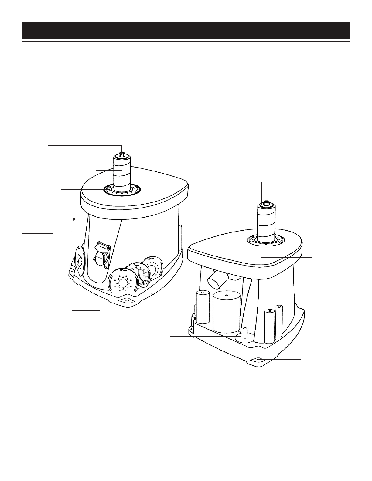
Refer to the diagram below to become familiarized with the parts and controls of your spindle sander.
Spindle
Sanding Drum & Sleeve
Spindle Upper Washer
Throat Plate
FRONT
VIEW
ON/OFF Switch
with Safety Key
Accessory Storage
(On 3 sides of the machine)
CLEANING THE WORK TABLE SURFACE
Work Table
Dust Port
Rubber
Sanding
Drums
Mounting Holes
Your sander's work table comes protected with a layer of anti-rust coating. Clean the rust-protected surfaces
using a soft cloth, moistened with kerosene. Do not use gasoline, or cellulose-based solvents such as paint
thinner or lacquer thinner, as these will damage the painted surfaces.
After cleaning, apply a coat of paste wax to the table to prevent rust. Wipe all parts thoroughly with a clean,
dry cloth.
9
Page 10

ASSEMBLY & ADJUSTMENTS
Before using the spindle sander, you must configure the machine by installing the appropriate sanding drum,
sanding sleeve, throat plate and spindle washer for your operation. Check your packing list against the diagram below. If any part is damaged or missing, please contact our customer service at (800) 232-1195, M-F
8-5 CST or email us at [email protected].
PACKING LIST
80-Grit Sanding Sleeves (6)
Rubber Sanding Drums (5)
Sanding Throat Plates (6)
Upper Spindle Washer Size
1/2˝/ .5
(13 mm)
˝
3/4˝/ .75
(19 mm)
˝
(26 mm)
1
˝
1-1/2"/ 1.5
(38 mm)
NOTE: 1/2˝
sanding
sleeve fits
directly on
the spindle.
Small Medium Large
˝
2"
(51 mm) (76 mm)
3"
Spindle with
Lock Nut
The following replacement sanding sleeves can be purchased from wenproducts.com by searching their
respective model numbers: WEN 80-Grit Sanding Sleeves (model 6510SP80), WEN 120-Grit Sanding
Sleeves (model 6510SP120), WEN 150-Grit Sanding Sleeves (model 6510SP150), WEN 240-Grit Sanding
Sleeves (model 6510SP240), and the WEN Assorted Sanding Sleeve Combo Pack (model 6510SPC).
10
Spindle Nut
Wrench
S M L
Spindle Washers
(3 Upper, 1 Lower)
Page 11
ASSEMBLY & ADJUSTMENTS
WARNING: Do not plug in or turn on the tool until it is fully assembled according to the instruc-
tions. Failure to follow the safety instructions may result in serious personal injury.
ACCESSORY SELECTION
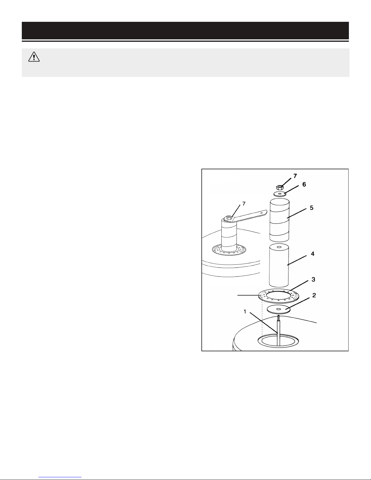
Refer to the packing list diagram on page 10 to ensure that you are using the proper sizes of throat plates,
drums and washers for each respective sanding sleeve. To ensure the workpiece can be properly supported
and to minimize clearance, use the throat plate that matches the drum and sleeve that you’ll be working with.
The size of the throat plate is marked on the plate's surface.
NOTE: The smallest size sanding sleeve does not include a drum. It goes directly onto the bare spindle.
INSTALLING THE ACCESSORIES
1. Disconnect the machine from the power source.
2. Slide the lower spindle washer (Fig. 2 - 2) over the
spindle shaft.
3. Install the preferred rubber drum (Fig. 2 - 4) onto the
spindle shaft, followed by the corresponding sanding
sleeve (Fig. 2 - 5) and throat plate (Fig. 2 - 3). Make
sure the printed side of the throat plate is facing up.
NOTE: The 1/2" sleeve will be installed directly onto the
spindle.
4. Secure the sanding accessories in place with the corresponding washer (Fig. 2 - 6). Tighten the spindle nut
on top (Fig. 2 - 7) with the spindle nut wrench until the
sanding drum is fully expanded and securely holds the
sanding sleeve. The sleeve should not be able to freely
rotate without also rotating the sanding drum.
Fig. 1
Align the
notch
11
Page 12
ASSEMBLY & ADJUSTMENTS
WARNING: Do not plug in or turn on the tool until it is fully assembled according to the instruc-
tions. Failure to follow the safety instructions may result in serious personal injury.
MACHINE MOUNTING
For safe operation, the machine must be secured onto a flat, secure workbench or stand. The base of the machine has four 6 mm mounting holes. Place the sander on the mounting surface, and insert a pencil through
the mounting holes to mark the hole locations. Remove the sander and drill out the mounting holes. Then
align the sander base over the mounting holes and secure the machine using four mounting bolts, washers,
locking washers and hex nuts (mounting hardware not included). Securely tighten the hex nuts.
For temporary mounting, secure the sander to a mobile mounting board and use 2 large C-Clamps to secure
the mounting board to a solid surface.
TIP: Your spindle sander is compatible with the WEN 6588 or 6588T Multipurpose Planer Stand, available
at wenproducts.com. Forget measuring and drilling holes on your workbench. Simply mount your ma-
chine onto the stand with pre-drilled holes, and transport your machine around the workshop with ease
.
DUST COLLECTION
WARNING: Sanding operations are dusty and
can produce particles that are harmful to your
health. Always wear a dust mask and use an
adequate dust collection system.
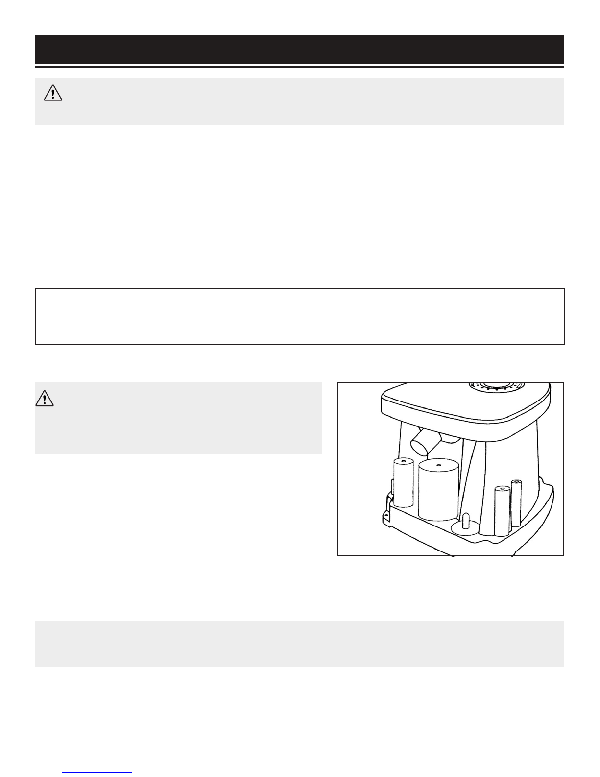
To connect a dust collection system to the machine:
1. Fit a 1.5-inch dust hose (not included) over the dust port
and secure the hose in place with a hose clamp as needed.
2. Tug the hose to make sure the fitting is tight. A tight fit
is necessary for proper performance.
3. Connect the other end of the dust hose to the dust collection system of your choice. A dust port adapter
may be needed (not included), depending on the inlet size of your dust extractor. The dust port has an outer
diameter of 1.5 inches, and an inner diameter of 1.4 inches.
NOTE: Failure to use a dust collection system will void the warranty on this item. You must use a dust
collection system for the warranty to be valid.
Fig. 2
12
Page 13
OPERATION
ON/OFF SWITCH WITH SAFETY KEY
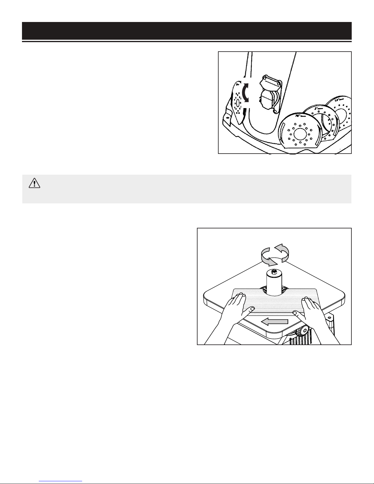
The keyed ON/OFF switch (Fig. 4) is intended to prevent
unauthorized use of the sander.
1. To turn the sander ON, insert the safety key into the key
slot in the center of the switch. Lift the switch up to turn
ON the sander.
3. To turn the sander OFF, push switch down. Remove the
safety key when the sander has come to a complete stop
by gently pulling it out.
WARNING: Remove the safety key whenever the sander is not in use. Place the key in a safe
place and out of the reach of children.
Fig. 3
ON
OFF
OPERATING THE SPINDLE SANDER
1. Make sure that the machine has been securely
mounted, and all accessories have been properly
installed according to the instructions in the "ASSEMBLY & ADJUSTMENTS" section.
Fig. 4
2. Plug in and turn ON the sander. Let the spindle
reach full speed.
3. Maintain a firm grip with both hands on the
workpiece for maximum control. Slowly guide the
workpiece against the rotation of the spindle
(Fig. 5).
NOTE: The spindle rotates in a counterclockwise
direction. Guide the workpiece from the right to left.
If you guide the workpiece in the opposite direction, the
forces of the spinning sanding sleeve will tend to throw or bounce the workpiece away from the sanding sleeve, possibly resulting in injuries.
4. Maintain downward pressure on the workpiece against the table, gently working it along the sanding
sleeve until the desired curve has been created. Do not force the workpiece against the sanding sleeve.
5. When you are finished, turn OFF the sander and wait for the spindle to come to a complete stop.
6. Remove the safety key and unplug the machine from the outlet. Follow the maintenance instructions
on the next page to clean and maintain your sander.
13
Page 14

MAINTENANCE
WARNING: To avoid accidents, turn OFF and unplug the tool from the electrical outlet before
cleaning, adjusting, or performing any maintenance or lubrication work.
WARNING: Any attempt to repair or replace electrical parts on this tool may be hazardous.
Servicing of the tool must be performed by a qualified technician. When servicing, use only identical WEN replacement parts. Use of other parts may be hazardous or induce product failure.
ROUTINE INSPECTION
Before each use, inspect the general condition of the tool. If any of these following conditions exist, do not
use until parts are replaced or the sharpener is properly repaired.
Check for:
• Loose hardware or improper mounting,
• Misalignment or binding of moving parts,
• Damaged cord/electrical wiring,
• Cracked or broken parts, and
• Any other condition that may affect its safe operation
CLEANING & STORAGE
1. After every operation, use a vacuum to remove dust and chips from the tool surfaces, motor housing
and work area. Keep the ventilation openings free from dust and debris to prevent the motor from overheating.
2. Wipe the tool surfaces clean with a soft cloth or brush. Make sure water does not get into the tool.
3. Periodically, remove the throat plate and lower spindle washer and remove any dust accumulation in the
throat plate area.
CAUTION: Most plastics are susceptible to damage from various types of commercial solvents.
Do not use any solvents or cleaning products that could damage the plastic parts. Some of these
include but are not limited to: gasoline, carbon tetrachloride, chlorinated cleaning solvents, and
household detergents that contain ammonia.
4. Store the tool in a clean and dry place away from the reach of children. Store sanding accessories
away from extremely hot/dry temperatures. Do not bend or fold the sanding sleeves.
LUBRICATION
All ball bearings are sealed and permanently lubricated. No further lubrication is required.
PRODUCT DISPOSAL
Used power tools should not be disposed of together with household waste. This product contains
electronic components that should be recycled. Please take this product to your local recycling facility for responsible disposal and to minimize its environmental impact.
14
Page 15

TROUBLESHOOTING GUIDE
WARNING: Stop using the tool immediately if any of the following problems occur. Repairs and
replacements should only be performed by an authorized technician. For any questions, please
contact our customer service at (800) 232-1195, M-F 8-5 CST or email us at techsupport@wenproducts.com.
PROBLEM CAUSE SOLUTION
Sander does
not turn on
Motor
overheats
Sanding grains
easily rub off
Deep sanding
grooves or
scars in workpiece.
1. Power cord or extension cord damaged or not properly plugged in.
2. Safety key is removed from power
switch.
3. Defective power switch, defective
motor or wiring, short circuit or loose
connections.
1. Motor overloaded.
2. Extension cord too long with an
insufficient gauge.
1. Sanding sleeve has been stored in
an incorrect environment.
2. Sanding sleeve has been damaged
or folded.
1. Sanding sleeve grit is too coarse
for the desired finish.
2. Workpiece sanded across the grain.
3. Too much sanding force.
4. Workpiece held still against sanding surface for too long.
1. Check the power cord, extension cord, power plug
and the power outlet. Make sure the tool is properly
plugged in. Do not use the if any cord is damaged.
2. Insert the safety key into the power switch.
3. Stop using the tool and contact customer service
at (800) 232-1195, M-F 8-5 CST for assistance.
Repairs must be done by a qualified technician.
1. Reduce load on motor - reduce pressure on the
workpiece being sanded.
2. Utilize an extension cord of appropriate gauge and
length or plug tool directly into outlet (see page 8).
1. Store sanding accessories away from extremely
hot/dry temperatures.
2. Store sanding accessories flat—not bent or
folded.
1. Use a finer-grit sanding accessory.
2. Sand with the grain of the wood.
3. Reduce pressure on workpiece while sanding.
4. Keep workpiece moving while sanding on the
sanding sleeve.
1. Using a sanding grit that is too fine.
Burns on
workpiece
Sanding
surface clogs
quickly
Sander
vibrates excessively or has
noisy operation.
Sanding stops
oscillating
2. Using too much pressure.
3. Work held still for too long.
4. Sanding sleeve loaded with debris.
1. Too much pressure against sleeve.
2. Sanding softwood.
1. Sanding sleeve out of balance or is
loose.
2. Motor or internal components
loose.
3. Machine not properly mounted.
4. Faulty motor bearings.
Spindle drive belt is broken and requires replacement.
1. Use a coarser-grit sanding accessory.
2. Reduce sanding pressure on workpiece.
3. Do not keep workpiece in one place for too long.
4. Clean or replace the sanding sleeve.
1. Clean sanding sleeve. Reduce pressure on workpiece while sanding.
2. Use different stock/sanding accessories, or accept
that this will happen and plan on cleaning or replacing sleeves frequently.
1. Ensure sleeve is properly installed.
2. Inspect/replace damaged bolts/nuts and retighten
with thread-locking fluid.
3. Tighten mounting hardware.
4. Test by rotating shaft; rotational grinding/loose
shaft requires bearing replacement.
Contact customer service at (800) 232-1195, M-F
8-5 CST for assistance. Repairs must be done by a
qualified technician.
15
Page 16
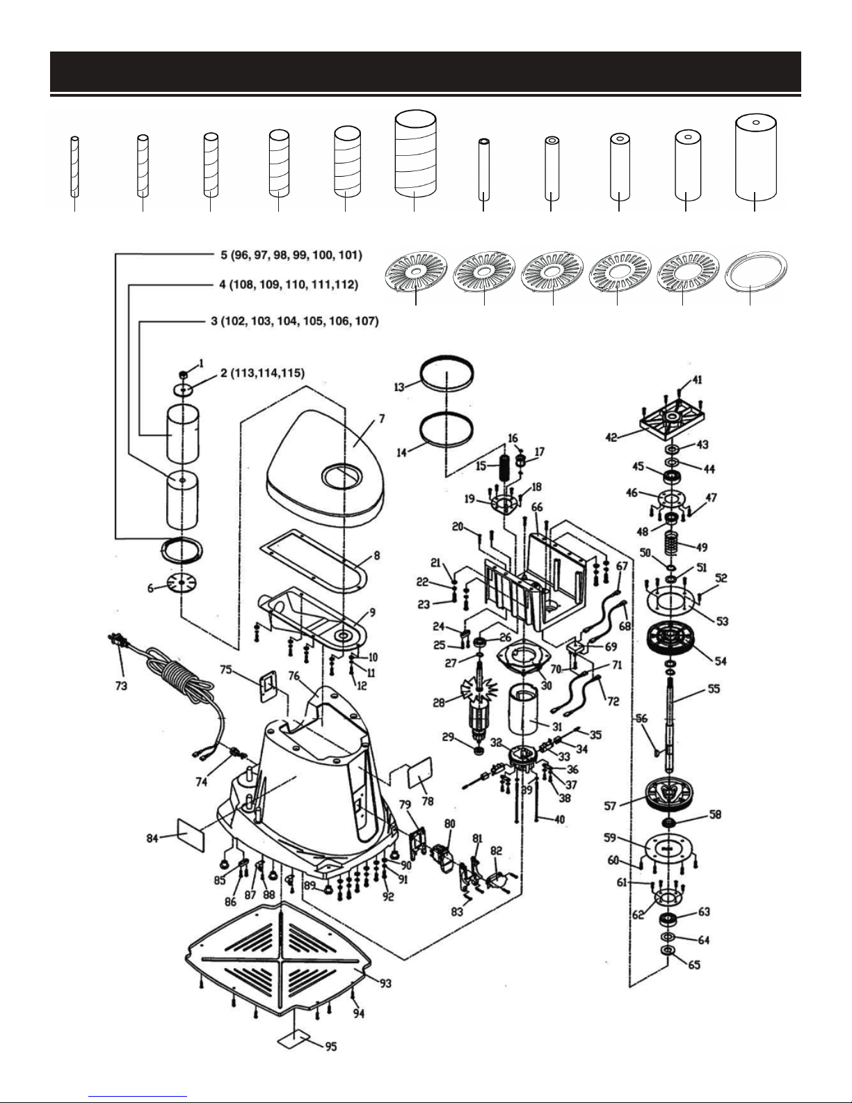
EXPLODED VIEW & PARTS LIST
102 103 104 105 106 107
96 97 98 99 100 101
108 109 110 111 112
16
Page 17

EXPLODED VIEW & PARTS LIST
No. Part No. Description Qty.
1 90225-001 Hex Nut M8 1
2 90225-002 Upper Spindle Washer 1
3 90225-003 Sander Sleeve 1
4 90225-004 Rubber Spindle 1
5 90225-005 Throat Plate 1
6 90225-006 Lower Spindle Washer 1
7 90225-007 Cast Iron Table 1
8 90225-008 Dust Washer 1
9 90225-009 Dust Cover 1
10 90225-010 Washer 5 5
11 90225-011 Spring Washer 5 5
12 90225-012 Screw 5x12 5
13 90225-013 Belt 1
14 90225-014 Belt II 1
15 90225-015 Belt Wheel 1
No. Part No. Description Qty.
32 90225-032 Rear Cover 1
33 90225-033 Brush Holder 2
34 90225-034 Carbon Brush 2
35 90225-035 Brush Spring 2
36 90225-036 Cord Clamp 2
37 90225-037 Washer 4 4
38 90225-038 Screw 4.2x13 4
39 90225-039 Washer 4 2
40 90225-040 Screw 4.2x110 2
41 90225-041 Screw 4.2x22 4
42 90225-042 Bearing Cover 1
43 90225-043 Felt 1
44 90225-044 Rubber Washer 1
45 90225-045 Bearing 6203zz 1
46 90225-046 Bearing Support 1
16 90225-016 Spring Washer 2
17 90225-017
18 90225-018 Screw 4.2x13 4
19 90225-019
20 90225-020 Screw 4.2x22 4
21 90225-021 Washer 6 4
22 90225-022 Spring Washer 6 4
23 90225-023 Screw 6x16 4
24 90225-024 Cord Clamp 1
25 90225-025 Screw 4.2x15 2
26 90225-026 Bearing 6001zz 1
27 90225-027 Spring Washer 1
28 90225-028 Armature Assembly 1
29 90225-029 Bearing 608zz 1
30 90225-030 Connection Plate 1
31 90225-031 Field Assembly 1
Tension Roller Assem-
bly
Orientation Plate
Assembly
47 90225-047 Screw 4.2x15 4
1
1
48 90225-048 Bearing Sleeve 1
49 90225-049 Spring 1
50 90225-050 Spring Washer 2
51 90225-051 Spindle Washer 2
52 90225-052 Screw 4.2x13 4
53 90225-053 Wheel Plate 1
54 90225-054 Wheel 1 1
55 90225-055 Spindle 1
56 90225-056 Pin 1
57 90225-057 Wheel 2 1
58 90225-058 Bearing Sleeve 1
59 90225-059 Wheel Plate 1
60 90225-060 Screw 4.2x13 4
61 90225-061 Screw 4.2x13 4
62 90225-062 Bearing Support 1
63 90225-063 Bearing 6203zz 1
17
Page 18

EXPLODED VIEW & PARTS LIST
No. Part No. Description Qty.
64 90225-064 Rubber Washer 1
65 90225-065 Felt 1
66 90225-066 Wheel Support 1
67 90225-067 Wire Assembly 1 1
68 90225-068 Wire Assembly 2 1
69 90225-069 Rectifier 1
70 90225-070 Screw 4.2x19 1
71 90225-071 Wire Assembly 3 1
72 90225-072 Wire Assembly 4 1
73 90225-073 Power Cord 1
74 90225-074 Cord Clamp 1
75 90225-075
76 90225-076 Housing Base 1
78 90225-078 Logo Label 1
79 90225-079 Switch Orientation 1 1
80 90225-080 Switch 1
81 90225-081 Switch Orientation 2 1
82 90225-082
83 90225-083 Screw 4x16 4
84 90225-084 Warning Label 1 1
85 90225-085 Cord Clamp 1
86 90225-086 Screw 4.2x15 2
87 90225-087 Thread 2
88 90225-088 Screw 4.2x10 2
Switch Orientation
Plate
Switch Assistant Orien-
tation
1
1
No. Part No. Description Qty.
92 90225-092 Screw 6x16 6
93 90225-093 Bottom Plate 1
94 90225-094 Screw 4.2x13 6
95 90225-095 Warning Label 2 1
96 90225-096 1/2” Throat Plate
97 90225-097 3/4” Throat Plate 1
98 90225-098 1” Throat Plate 1
99 90225-099 1-1/2” Throat Plate 1
100 90225-100 2” Throat Plate 1
101 90225-101 3” Throat Plate 1
102 90225-102
103 90225-103
104 90225-104
105 90225-105
106 90225-106
107 90225-107
108 90225-108 3/4” Rubber Spindle 1
109 90225-109 1” Rubber Spindle 1
110 90225-110 1-1/2” Rubber Spindle 1
111 90225-111 2” Rubber Spindle 1
112 90225-112 3” Rubber Spindle 1
1/2” Sanding Sleeve
(80 Grit)
3/4” Sanding Sleeve
(80 Grit)
1” Sanding Sleeve
(80 Grit)
1-1/2” Sanding Sleeve
(80 Grit)
2” Sanding Sleeve
(80 Grit)
3” Sanding Sleeve
(80 Grit)
1
1
1
1
1
1
89 90225-089 Rubber Foot 4
90 90225-090 Washer 6 6
91 90225-091 Spring Washer 6 6
18
Page 19

WARRANTY STATEMENT
WEN Products is committed to building tools that are dependable for years. Our warranties are consistent
with this commitment and our dedication to quality.
LIMITED WARRANTY OF WEN CONSUMER POWER TOOLS PRODUCTS FOR HOME USE
GREAT LAKES TECHNOLOGIES, LLC (“Seller”) warrants to the original purchaser only, that all WEN consumer power tools will be free from defects in material or workmanship for a period of two (2) years from
date of purchase. Ninety days for all WEN products if the tool is used for professional or commercial use.
SELLER’S SOLE OBLIGATION AND YOUR EXCLUSIVE REMEDY under this Limited Warranty and, to the extent permitted by law, any warranty or condition implied by law, shall be the repair or replacement of parts,
without charge, which are defective in material or workmanship and which have not been misused, carelessly handled, or misrepaired by persons other than Seller or Authorized Service Center. To make a claim under
this Limited Warranty, you must make sure to keep a copy of your proof of purchase that clearly defines the
Date of Purchase (month and year) and the Place of Purchase. Place of purchase must be a direct vendor of
Great Lakes Technologies, LLC. Third party vendors such as garage sales, pawn shops, resale shops, or any
other secondhand merchant void the warranty included with this product. Contact techsupport@wenproducts.com or 1-800-232-1195 to make arrangements for repairs and transportation.
When returning a product for warranty service, the shipping charges must be prepaid by the purchaser.
The product must be shipped in its original container (or an equivalent), properly packed to withstand the
hazards of shipment. The product must be fully insured with a copy of the warranty card and/or the proof of
purchase enclosed. There must also be a description of the problem in order to help our repairs department
diagnose and fix the issue. Repairs will be made and the product will be returned and shipped back to the
purchaser at no charge.
THIS LIMITED WARRANTY DOES NOT APPLY TO ACCESSORY ITEMS THAT WEAR OUT FROM REGULAR
USAGE OVER TIME INCLUDING BELTS, BRUSHES, BLADES, ETC. ANY IMPLIED WARRANTIES SHALL BE
LIMITED IN DURATION TO TWO (2) YEARS FROM DATE OF PURCHASE. SOME STATES IN THE U.S., SOME
CANADIAN PROVINCES DO NOT ALLOW LIMITATIONS ON HOW LONG AN IMPLIED WARRANTY LASTS,
SO THE ABOVE LIMITATION MAY NOT APPLY TO YOU.
IN NO EVENT SHALL SELLER BE LIABLE FOR ANY INCIDENTAL OR CONSEQUENTIAL DAMAGES (INCLUDING BUT NOT LIMITED TO LIABILITY FOR LOSS OF PROFITS) ARISING FROM THE SALE OR USE OF THIS
PRODUCT. SOME STATES IN THE U.S. AND SOME CANADIAN PROVINCES DO NOT ALLOW THE EXCLUSION OR LIMITATION OF INCIDENTAL OR CONSEQUENTIAL DAMAGES, SO THE ABOVE LIMITATION OR
EXCLUSION MAY NOT APPLY TO YOU.
THIS LIMITED WARRANTY GIVES YOU SPECIFIC LEGAL RIGHTS, AND YOU MAY ALSO HAVE OTHER
RIGHTS WHICH VARY FROM STATE TO STATE IN THE U.S., PROVINCE TO PROVINCE IN CANADA AND
FROM COUNTRY TO COUNTRY.
THIS LIMITED WARRANTY APPLIES ONLY TO PORTABLE ELECTRIC TOOLS, BENCH POWER TOOLS, OUTDOOR POWER EQUIPMENT AND PNEUMATIC TOOLS SOLD WITHIN THE UNITED STATES OF AMERICA,
CANADA AND THE COMMONWEALTH OF PUERTO RICO. FOR WARRANTY COVERAGE WITHIN OTHER
COUNTRIES, CONTACT THE WEN CUSTOMER SUPPORT LINE.
THANKS FOR REMEMBERING
19
Page 20

THANKS FOR
REMEMBERING
 Loading...