

Page 1
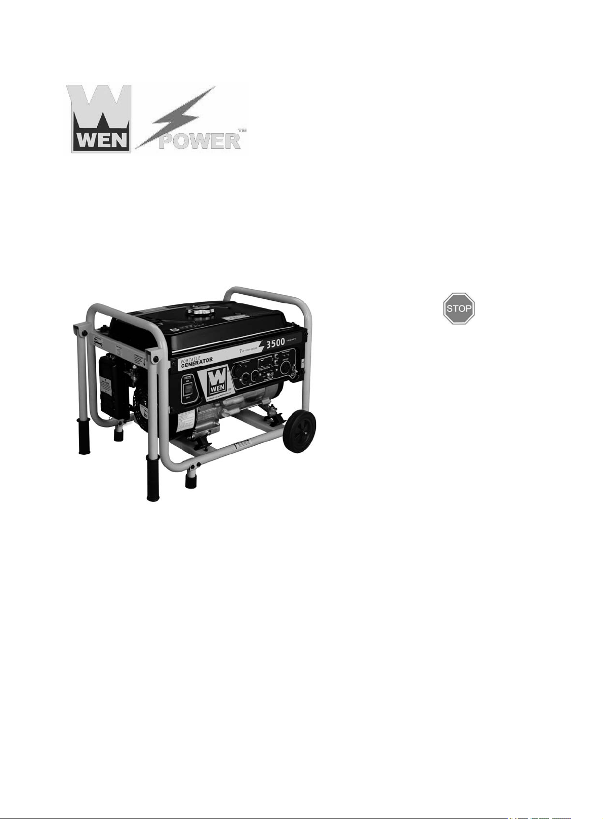
MODEL 3500
Questions? Problems?
Please call our customer help line:
(800) 232-1195 M-F 8-5 CST
HP Generator
Item # 56352
Owner’s Manual
Manual del Propietario
FEATURES
3500 Surge Watt Output
3000 Rated Watt Output
Powerful Enough to Run Essential Appliances During Power Outages
120 and 240 Volt AC Outputs
Low Oil Automatic Shutoff
Circuit Breaker for Overload Protection
4 Gallon Fuel Tank Capacity
Engine Hour Counter
Cigarette Lighter Style 12V DC Outlet
Spark Arrester
Meets EPA Emission Standards
Page 2

Page 3
i
GENERATOR IDENTIFICATION
Date
Date
Date
Date
Date
Date
Oil Change
Change spark plug
Clean Fuel Tank
Clean Filter Cup
Clean Air Cleaner
For information and questions, please contact the Customer Service Help Line by calling 800-232-
1195. Certain information will be requested by the Customer Service Representative and to facilitate
that, please fill in the information below.
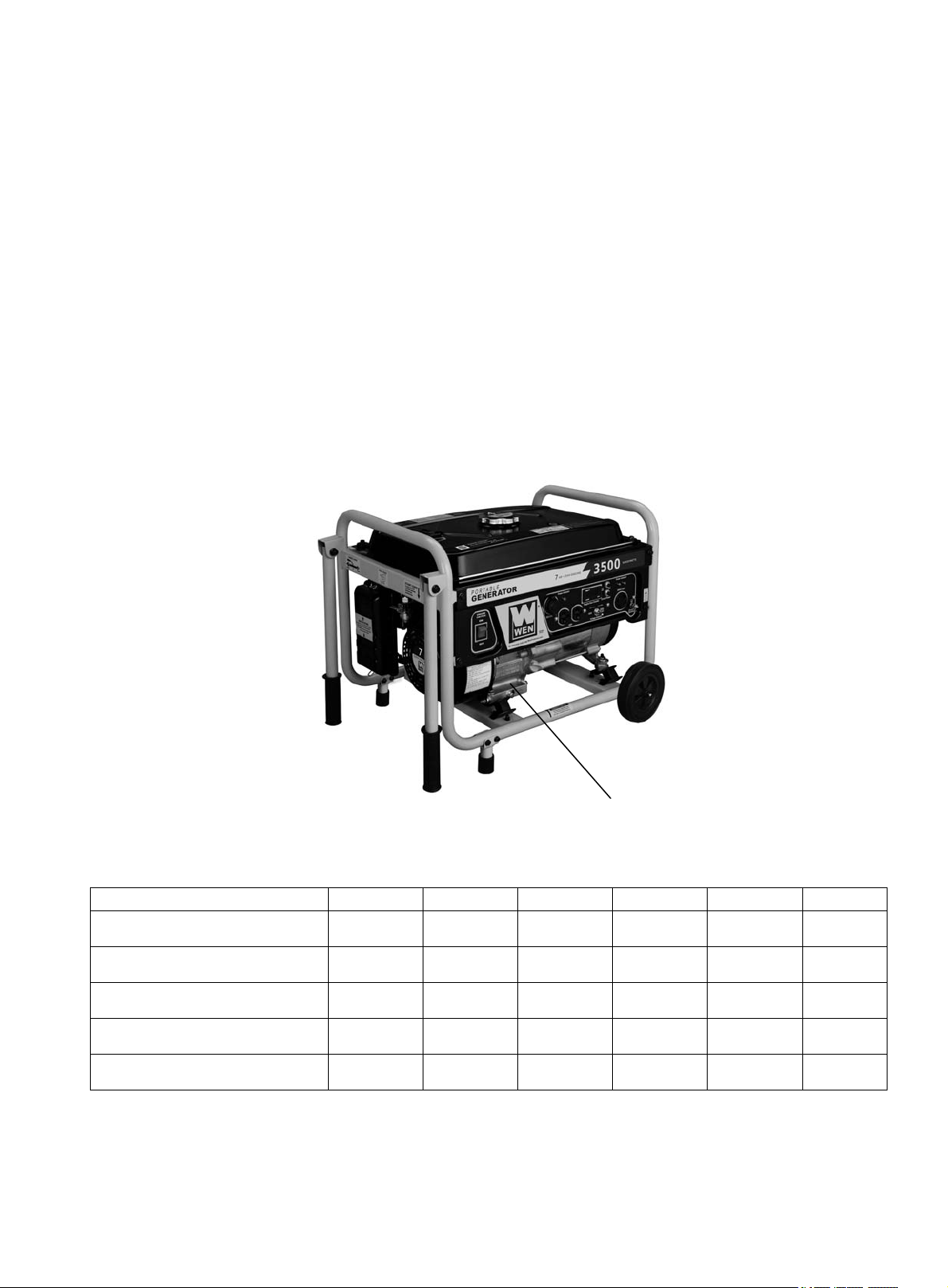
Refer to the illustration below for the location of Serial Number. Record generator information in the
spaces provided below.
DATE OF PURCHASE: ______________________________________________
PURCHASED FROM: ______________________________________________
GENERATOR MODEL NUMBER: ____________________________________
ENGINE SERIAL NUMBER: _________________________________________
SERVICE RECORD
Record Service Dates:
ENGINE SERIAL NUMBER
Page 4

ii
TABLE OF CONTENTS
GENERATOR IDENTIFICATION ................................................................................................ i
SERVICE RECORD ......................................................................................................................... i
INTRODUCTION ............................................................................................................................ 1
SAFETY INFORMATION .............................................................................................................. 2
GENERAL SAFETY PROCEDURES ........................................................................................... 3
IMPORTANT SAFETY INSTRUCTIONS ................................................................................... 5
PACKAGE CONTENTS ................................................................................................................. 8
GENERATOR COMPONENTS ..................................................................................................... 9
ASSEMBLY .................................................................................................................................... 10
Attach Feet ................................................................................................................................ 10
Attach Handles ......................................................................................................................... 11
Attach Wheels ........................................................................................................................... 11
GENERATOR PREPARATION .................................................................................................. 13
Using the Generator for the First Time ........................................................................................ 13
Step 1 - Fill Oil ......................................................................................................................... 13
Step 2- Add Gasoline ................................................................................................................ 14
Step 3- Ground the Generator ................................................................................................... 15
STARTING THE GENERATOR ................................................................................................. 16
SUBSEQUENT STARTING OF THE GENERATOR ............................................................... 17
Step 1- Check the Oil................................................................................................................ 17
Step 2 – Check the Fuel Level .................................................................................................. 18
Step 3- Ground the Generator ................................................................................................... 18
USING THE GENERATOR ......................................................................................................... 19
AC Usage ...................................................................................................................................... 19
DC Usage ...................................................................................................................................... 22
STOPPING THE GENERATOR.................................................................................................. 22
MAINTENANCE / CARE ............................................................................................................. 23
Cleaning the Generator ................................................................................................................. 23
Checking the Oil ........................................................................................................................... 23
Changing/ Adding Oil .................................................................................................................. 24
Air Cleaner Maintenance .............................................................................................................. 25
Fuel Filter Cup Cleaning .............................................................................................................. 25
Spark Plug Maintenance ............................................................................................................... 26
Draining the Fuel Tank ................................................................................................................. 26
STORAGE / TRANSPORT PROCEDURES .............................................................................. 27
SPECIFICATIONS ........................................................................................................................ 28
TROUBLESHOOTING ................................................................................................................. 29
EXPLODED VIEW AND PARTS LIST ...................................................................................... 30
WIRING DIAGRAM ..................................................................................................................... 34
WARRANTY STATEMENT ........................................................................................................ 36
Page 5

1
INTRODUCTION
Thank You for Purchasing a WEN Power TM Product.
.
This manual provides information regarding the safe operation and maintenance of this product.
Every effort has been made to ensure the accuracy of the information in this manual.
WEN Power
prior notice.
Please keep this manual available to all users during the entire life of the generator.
TM
reserves the right to change this product and specifications at any time without
Special Messages
This manual contains special messages to bring attention to potential safety concerns, generator
damage as well as helpful operating and servicing information. Please read all the information
carefully to avoid injury and machine damage.
Questions? Problems?
In order to answer questions and solve problems in the most efficient and speedy manner,
contact Customer Service at:
(800) 232-1195 M-F 8-5 CST
NOTICE REGARDING EMISSIONS
Engines that are certified to comply with U.S. EPA emission regulations for SORE (Small Off
Road Equipment), are certified to operate on regular unleaded gasoline, and may include the
following emission control systems: (EM) Engine Modifications and (TWC) Three-Way Catalyst
(if so equipped).
Page 6
SAFETY INFORMATION
Before operating this generator read and observe all warnings, cautions, and instructions on
this sheet, on the generator, and in the Owner’s Manual.
NOTE: The following safety information is not meant to cover all possible conditions and
situations that may occur. Read the entire Owner’s Manual for safety and operating
instructions. Failure to follow instructions and safety information could result in serious
injury or death.
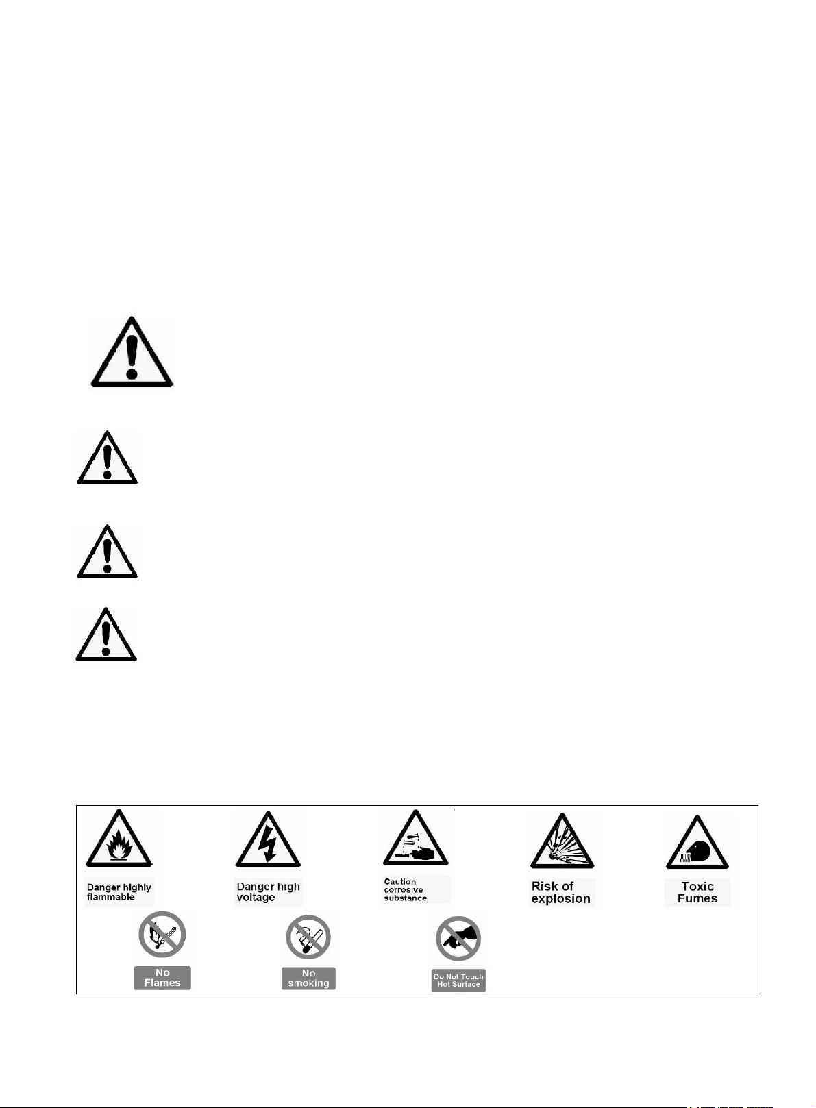
This safety alert symbol is used to identify safety information about hazards that can result in
personal injury.
A signal word (DANGER, WARNING, or CAUTION) is used
with the alert symbol to indicate the likelihood and the potential severity of injury.
In addition, a hazard symbol may be used to represent the type of hazard.
DANGER indicates a hazard, which, if not avoided, will result in death or serious
injury.
WARNING indicates a hazard, which, if not avoided, could result in death or
serious injury.
CAUTION indicates a hazard, which, if not avoided, might result in minor or
moderate injury.
CAUTION, when used without the alert symbol, indicates a situation that could
result in damage to the engine or generator.
SAFETY SYMBOLS AND MEANINGS
2
Page 7
GENERAL SAFETY PROCEDURES
For any questions regarding the hazard and safety notices listed in this manual or on the
product, please call (800) 232-1195 M-F 8-5 CST before using the generator.
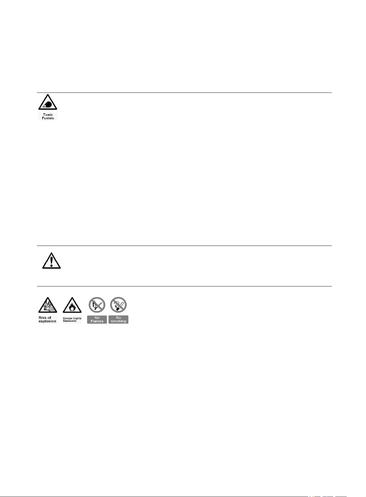
DANGER: CARBON MONOXIDE. Using a generator indoors CAN KILL
YOU IN MINUTES.
Generator exhaust contains carbon monoxide (CO). This is a poison gas you
cannot see or smell. If you can smell the generator exhaust, you are breathing CO.
But even if you cannot smell the exhaust, you could be breathing CO.
NEVER use a generator inside homes, garages, crawlspaces, or other partly enclosed
areas. Deadly levels of carbon monoxide can build up in these areas. Using a fan or
opening windows and doors does NOT supply enough fresh air.
ONLY use a generator outside and far away from windows, doors, and vents. These
openings can pull in generator exhaust.
Even if you use a generator correctly, CO may leak into the home. ALWAYS use a batterypowered or battery-backup CO alarm in the home.
If you start to feel sick, dizzy, or weak after the generator has been running, move to fresh
air RIGHT AWAY. See a doctor. You may have carbon monoxide poisoning.
WARNING: The exhaust from this product contains chemicals known to the
State of California to cause cancer, birth defects, or other reproductive harm.
WARNING: This generator may emit highly
flammable and explosive gasoline vapors, which can
cause severe burns or even death, if ignited. A nearby open flame can lead to
explosion even if not directly in contact with gasoline.
Do not operate near open flame.
Do not smoke near generator.
Always operate on a firm, level surface.
Always turn generator off before refueling. Allow generator to cool for at least 2
minutes before removing fuel cap. Loosen cap slowly to relieve pressure in tank.
Do not overfill fuel tank. Gasoline may expand during operation. Do not fill to the
top of the tank. Allow for expansion.
Always check for spilled fuel before operating.
Empty fuel tank before storing or transporting the generator.
Before transporting, turn fuel valve to off and disconnect spark plug wire.
3
Page 8

WARNING: This generator produces powerful voltage, which can
result in electrocution.
ALWAYS ground the generator before using it (see the “Ground the Generator”
portion of the “GENERATOR PREPARATION” section).
Generator should only be plugged into electrical devices, either directly or with an
extension cord. NEVER connect to a building electrical system without a qualified
electrician. Such connections must comply with local electrical laws and codes.
Failure to comply can create a back-feed, which may result in serious injury or death
to utility workers.
Use a ground fault circuit interrupter (GFCI) in highly conductive areas such as
metal decking or steel work. GFCIs are available in-line with some extension cords.
Do not use in rainy conditions.
Do not touch bare wires or receptacles (outlets).
Do not allow children or non-qualified persons to operate.
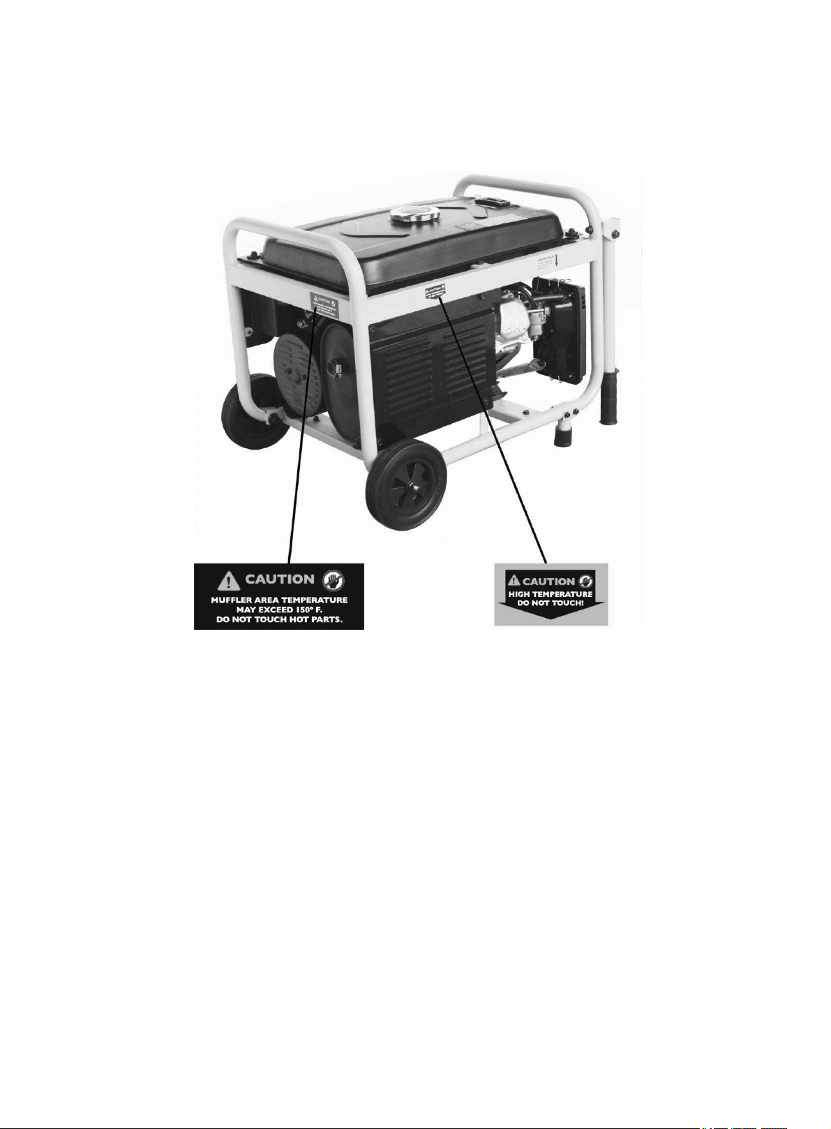
WARNING: This generator produces heat when running. Temperatures
near exhaust can exceed 150º F (65º C).
Do not touch hot surfaces. Pay attention to warning labels on the generator identifying
hot parts of the machine.
Allow generator to cool down after use before touching engine or areas of the generator
that become hot during use.
CAUTION: Misuse of this generator can damage it or shorten its life.
Use generator only for its intended purposes.
Operate only on dry, level surfaces.
Allow generator to run for several minutes before connecting electrical devices.
Shut off and disconnect any malfunctioning devices from generator.
Do not exceed the wattage capacity of the generator by plugging in more electrical devices
than the unit can handle.
Do not turn on electrical devices until after they are connected to the generator.
Turn off all connected electrical devices before stopping the generator.
Turn engine switch to “off” position when the engine is not running.
4
Page 9

IMPORTANT SAFETY INSTRUCTIONS
SAVE THESE INSTRUCTIONS – This manual contains important instructions for WEN
3500 generator that should be followed during installation and maintenance of the
generator.
Generators vibrate in normal use. During and after the use of the generator, inspect the
generator as well as extension and power supply cords connected to it for damage resulting
from vibration. Have damaged items repaired or replaced as necessary. Do not use plugs or
cords that show signs of damage such as broken or cracked insulation or damaged blades.
For power outages, permanently installed stationary generators are better suited for
providing backup power to the home. Even a properly connected portable generator can
become overloaded. This may result in overheating or stressing the generator components,
possibly leading to a generator failure.
WARNING: When this generator is used to supply a building wiring system:
Generator must be installed by a qualified electrician and connected to a transfer switch as
a separately derived system in accordance with the National Electrical Code, NFPA 70.
The generator shall be connected to a transfer switch that switches all conductors other than
the equipment grounding conductor. The frame of the generator shall be connected to an
approved grounding electrode.
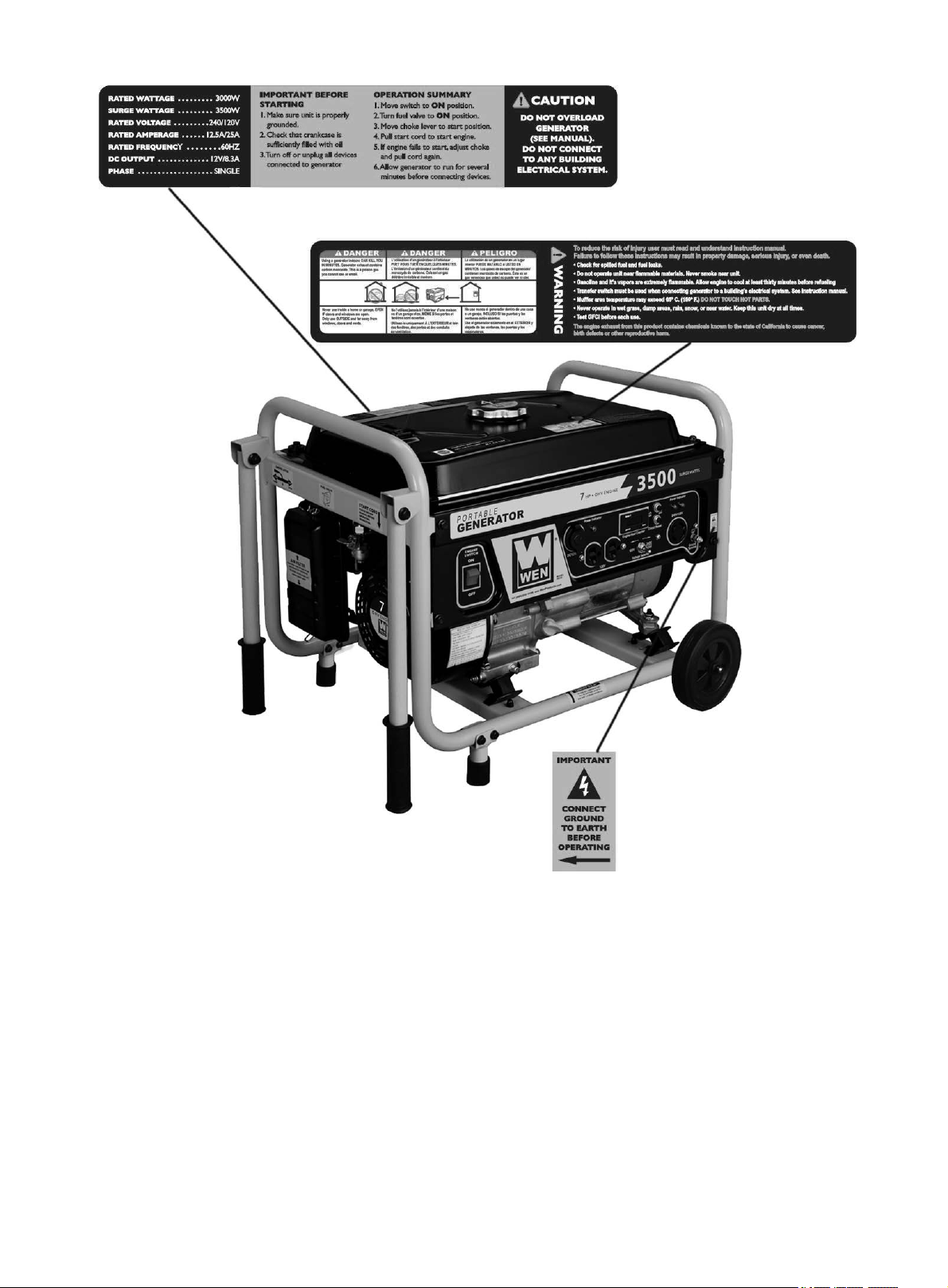
In addition to the previous safety notices, please become familiar with the safety and hazard
markings on the generator.
5
Page 10
6
Page 11
7
Page 12
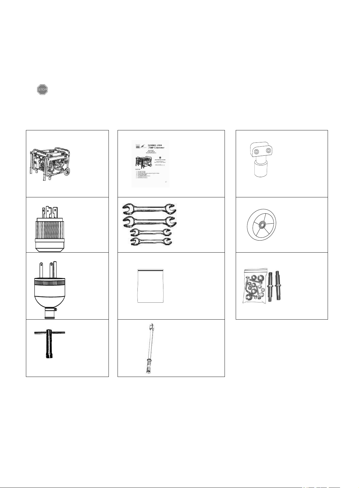
PACKAGE CONTENTS
Generator
Instruction
manual and
registration
card
Rubber
Foot (2pcs)
NEMA
L14-30
plug
Set of four
wrenches
for
assembly
Wheel
(2pcs)
Threeprong
plug
Vinyl Tool
Pouch
Wheel kit
hardware
Spark
plug
wrench
Handle
(2pcs)
Your generator comes with the items listed below. Please check to see that all of the following
items are included with your generator.
If there are any damaged or missing items, please call (800) 232-1195 M-F 8-5 CST for
customer service.
ITEM LIST
8
Page 13
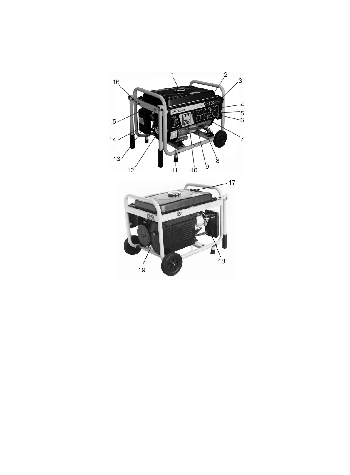
GENERATOR COMPONENTS
(1) Fuel Cap- Access to the fuel tank for adding
fuel.
(2) Voltage Selector-To switch between 120 and
240 Volt output.
(3) Circuit Reset Buttons- Reset buttons that protect
the generator from electrical overload.
(4) Power Indicator-Green lights that turn on to
indicate the output of power to each receptacle.
(5) 240/120 Volt AC Receptacle- To connect
electrical devices that run 120 and/or 240 Volt, 60
Hz, single phase, AC current.
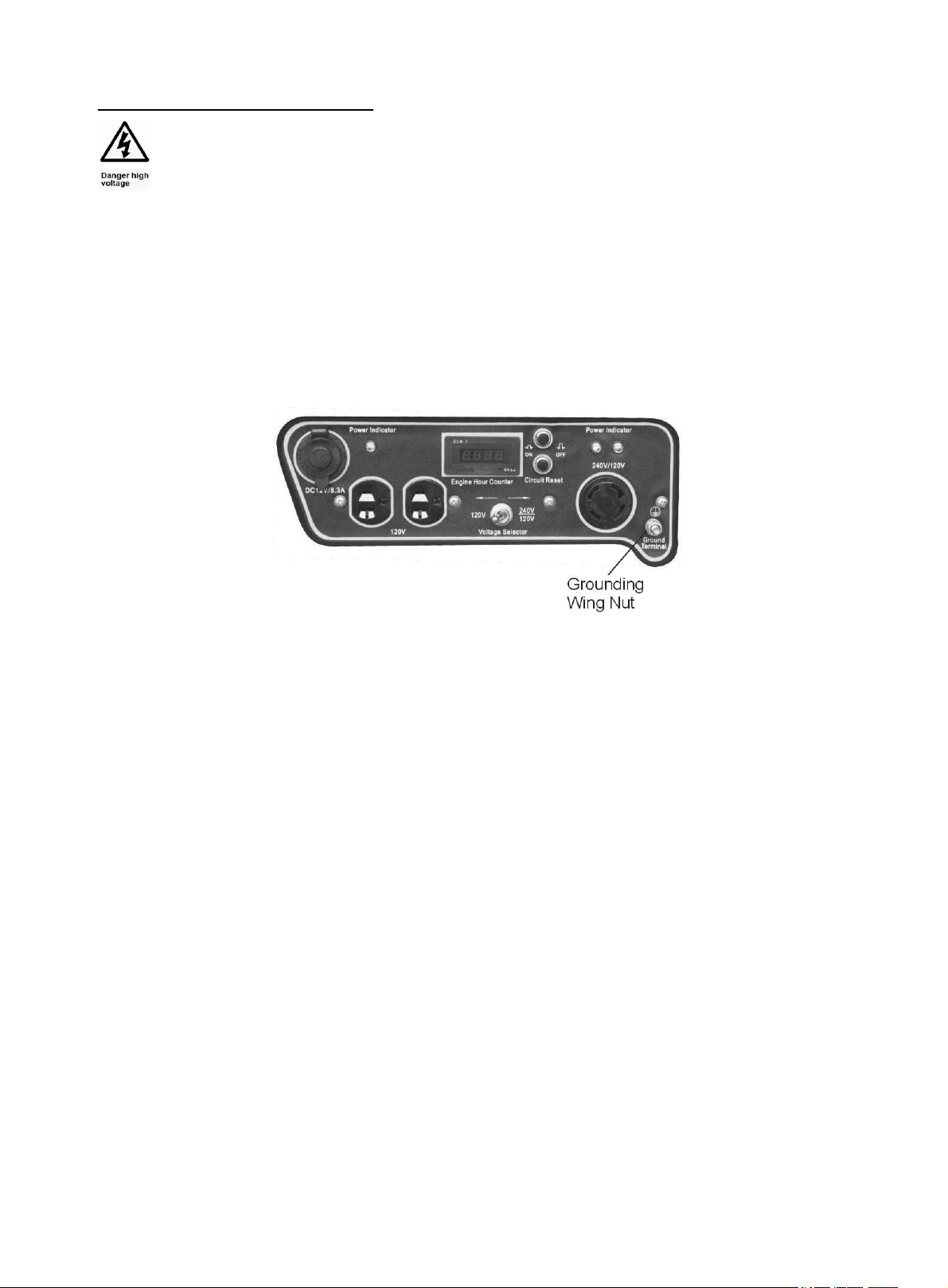
(6) Ground Terminal- Connect grounding wires
here to properly ground unit.
(7) Engine hour counter.
(8) 120 Volt AC Duplex Receptacle- To connect
electrical devices that run 120 Volt, 60 Hz, single
phase, AC current.
(9) 12V Cigarette lighter Style DC Receptacle.
(10) Oil Fill and Dipstick- Location for checking and
filling engine oil.
(11) Engine Switch- To start/stop engine.
(12) Recoil Starter- Pull-cord for starting engine.
(13) Fuel Filter Cup- Traps dirt from fuel before it enters
the engine.
(14) Air Cleaner- A removable, cleanable, sponge-like
element that limits the amount of dirt pulled into the engine.
(15) Choke Lever- Adjusts the amount of air let into the
engine.
(16) Fuel Valve- Allows fuel to enter engine.
(17) Fuel Gauge- Indicates the amount of fuel in the tank.
(18) Spark Plug- Provides proper engine ignition.
(19) Muffler- Reduces engine noise.
Please familiarize yourself with the locations and functions of the various components and controls
of your generator.
9
Page 14
ASSEMBLY
In order to best protect the generator while in the package, this product comes with some
components disassembled. Please complete the following assembly steps before proceeding to use
the generator. For ease of assembly, we recommend attaching the components in the order listed in
this manual.
If after reading this section, you are unsure about how to perform any of the steps, please call
(800) 232-1195 M-F 8-5 CST for customer service.
WARNING: This generator is heavy. Some assembly procedures may require
lifting equipment or two people.
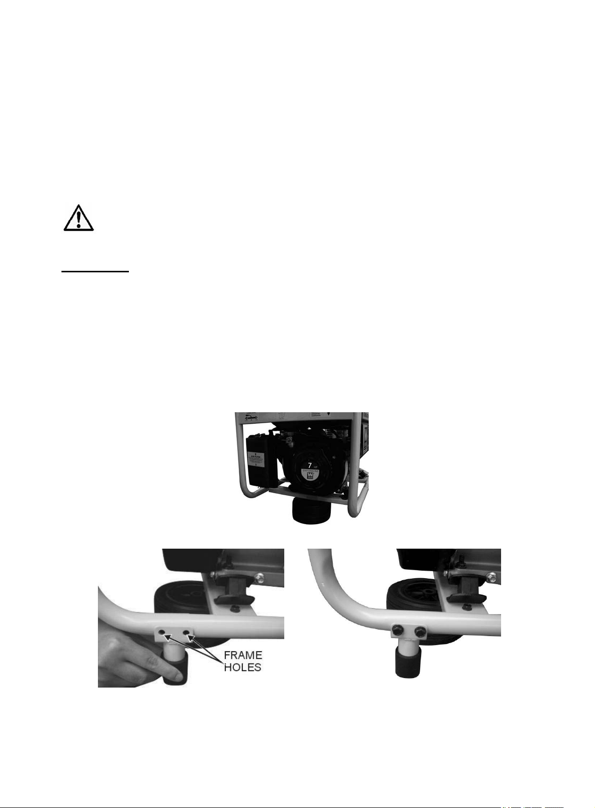
Attach Feet
To attach the feet to the generator, perform the following steps:
1. Stack the two generator wheels on top of each other. Lift the end of the generator that has
the recoil starter onto the stack of wheels (see figure 1). Be careful not to obstruct any
holes on the generator frame.
2. Place one leg onto the frame as shown in figure 2. Line up the holes on the generator
frame with the holes on the bracket portion of the leg. Tighten using two M6x40 bolts, two
M6 nuts, and the included wrench.
3. Repeat step 2 for the other generator leg.
Figure 1- Stacking the wheels
a b
Figure 2- foot assembly
10
Page 15
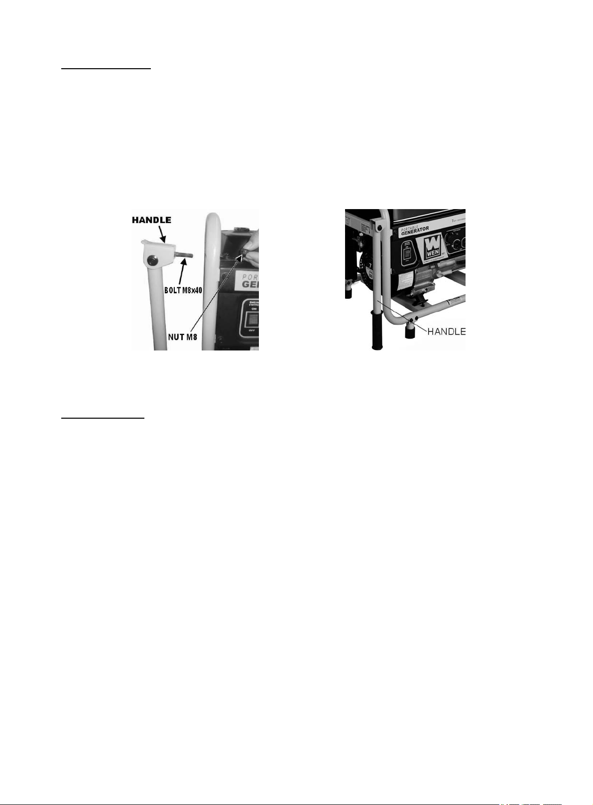
Attach Handles
The handles attach to the same end of the generator as the feet. To attach the handles to the
generator, perform the following steps:
1. Place one handle onto the upper portion of the generator frame as shown in figure 3.
2. Slide handle with M8×40 bolt attached through the hole and secure using an M8 nut.
3. Repeat steps 1 and 2 for the other side.
At this point, gently remove the two wheels from underneath the generator.
a b
Figure 3- handle assembly
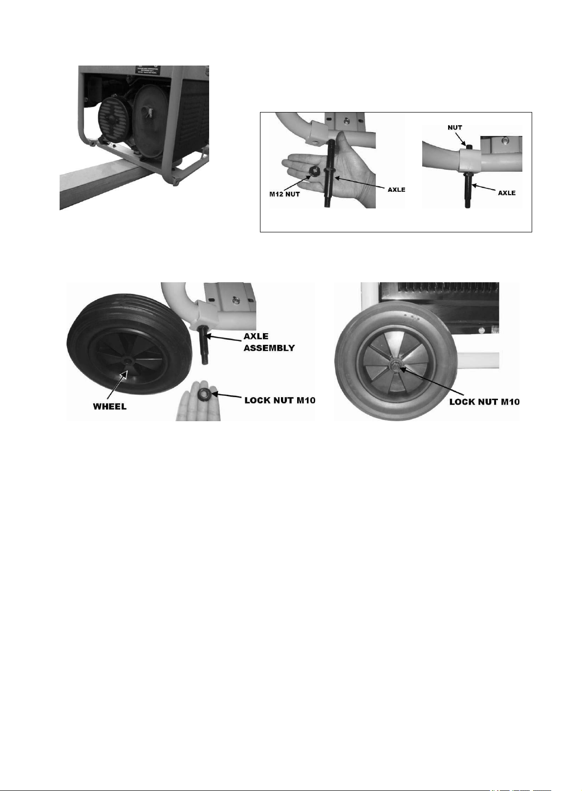
Attach Wheels
To attach the wheels to the generator, perform the following steps:
1. Find a wood block or similar item that is 3 inches thick or greater and rest the exhaust end
of the generator on the block as shown in figure 4.
2. Take one wheel shaft, and one M12 nut as shown. Slide the wheel shaft, with the threaded
part facing inward, through the frame. Secure using an M12 nut and the included wrench as
shown in figure 5.
3. Slide the wheel onto the axle and secure in place using a large cotter pin as shown in figure
6. Spread the pin legs apart slightly to help secure the pin in place.
4. Repeat steps 2 and 3 for the other wheel.
At this point, the generator assembly is complete. Gently remove the generator from the wood
block.
11
Page 16
a b
Figure 4- supporting the generator Figure 5- axle assembly
a b
Figure 6- wheel installation
12
Page 17
GENERATOR PREPARATION
Using the Generator for the First Time
The following section describes steps necessary to prepare the generator for use. If after
reading this section, you are unsure about how to perform any of the steps please call (800)
232-1195 M-F 8-5 CST for customer service. Failure to perform these steps properly can
damage the generator or shorten its life.
Step 1 - Fill Oil
The generator is shipped without oil. User must add the proper amount of oil before operating the
generator for the first time. The oil capacity of the engine crankcase is 20 fluid oz.
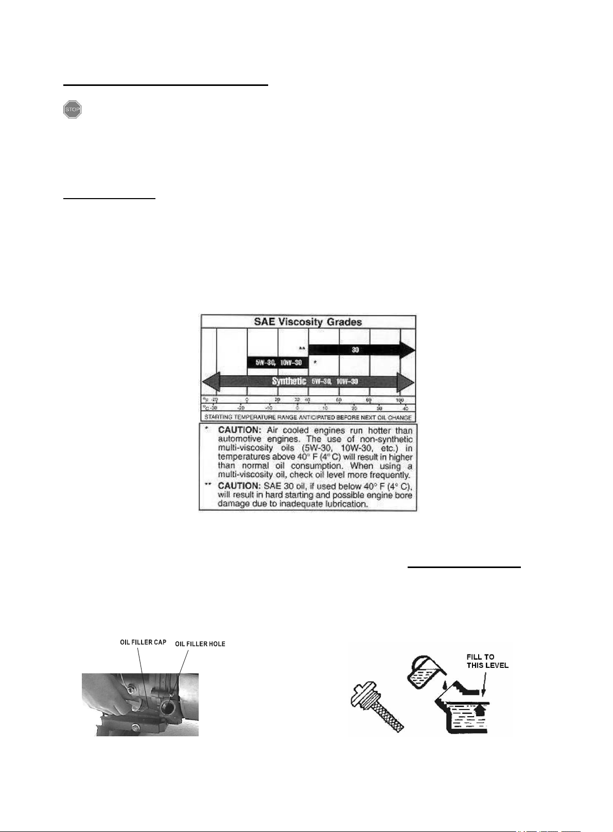
Select good quality detergent oil bearing the American Petroleum Institute (API) service
classifications SJ, SL, or SM. (Synthetic oils may be used.) Use the SAE viscosity grade
of oil from the following chart that matches the starting temperature anticipated before
the next oil changes.
Figure 7- Engine oil recommendations
To fill oil to the crankcase, follow these steps:
1. Make sure the generator is on a level surface. Tilting the generator to assist in filling will
cause oil to flow into engine areas and will cause damage. Keep generator level!
2. Remove the oil filler/dipstick cap from the engine as shown in figure 8.
3. Using a funnel, add the appropriate type and amount of oil into the crankcase. The
crankcase is full when the oil level has reached the second thread from the lip of the
opening (see figure 9).
4. Check for oil leaks. Reinstall oil filler cap before starting engine.
Figure 8- Unscrewing the oil cap Figure 9- filling oil
13
Page 18

Model number
3500
Fuel tank
capacity
15 L (4 gallons)
Step 2- Add Gasoline
WARNING: This generator may emit highly
flammable and explosive gasoline vapors, which can
cause severe burns or even death if ignited. A nearby
open flame can lead to explosion even if not directly in contact with gasoline.
Do not operate near open flame.
Do not smoke near generator.
Always operate on a firm, level surface.
Always turn generator off before refueling. Allow generator to cool for at least 2
minutes before removing fuel cap. Loosen cap slowly to relieve pressure in tank.
Do not overfill fuel tank. Gasoline may expand during operation. Do not fill to the
top of the tank. Allow for expansion.
Always check for spilled fuel before operating. Clean up any spilled fuel before
starting.
Empty fuel tank before storing or transporting the generator.
Before transporting, turn fuel valve to off position and disconnect spark plug wire.
Use fresh (within 30 days from purchase), unleaded gasoline with a minimum 87 octane rating. Do
not use gasoline which contains Methanol. Do not mix oil with gasoline.
To add gasoline, follow these steps:
1. Make sure the generator is on a level surface.
2. Unscrew fuel cap and set aside (NOTE: the fuel cap may be tight and hard to unscrew).
3. Slowly add unleaded gasoline to the fuel tank. Be careful not to overfill. Please refer to the
chart in figure 10 for the fuel capacity. The fuel gauge on the top of the generator indicates
how much gasoline is in the generator fuel tank. NOTE: Do not fill the fuel tank to the
very top. Gasoline will expand and spill over during use even with the fuel cap in place.
4. Reinstall fuel cap and wipe off any spilled gasoline with a dry cloth.
IMPORTANT:
Never use an oil/gasoline mixture.
Never use old gasoline.
Avoid letting dirt or water into the fuel tank.
Gasoline can age in the tank and make it hard to start up the generator in the future. Never
store generator for extended periods of time with fuel in the tank.
14
Figure 10- Fuel Tank Capacity
Page 19
Step 3- Ground the Generator
WARNING: Failure to properly ground the generator can result in
electrocution.
Ground the generator by tightening the grounding nut against a grounding wire (see figure 11). A
generally acceptable grounding wire is a No. 12 AWG (American Wire Gauge) stranded copper
wire. This grounding wire should be connected at the other end to a copper or brass grounding rod
that is driven into the earth. Wire and grounding rod are not included in generator contents.
Grounding codes can vary by location. Please contact a local electrician to check the grounding
regulations for your area.
Figure 11- Grounding nut location
NOTE: After completing the 3-step Generator Preparation, the generator is ready to be
started.
15
Page 20
STARTING THE GENERATOR
Before starting the generator, make sure you have read and performed the steps in the
“Generator Preparation” section of this manual. If you are unsure about how to perform any
of the steps in this manual please call (800) 232-1195 M-F 8-5 CST for customer service.
DANGER: CARBON MONOXIDE. Using a generator indoors CAN KILL
YOU IN MINUTES.
Generator exhaust contains carbon monoxide (CO). This is a poison gas you
cannot see or smell. If you can smell the generator exhaust, you are breathing CO.
But even if you cannot smell the exhaust, you could be breathing CO.
NEVER use a generator inside homes, garages, crawlspaces, or other partly enclosed
areas. Deadly levels of carbon monoxide can build up in these areas. Using a fan or
opening windows and doors does NOT supply enough fresh air.
ONLY use a generator outside and far away from windows, doors, and vents. These
openings can pull in generator exhaust.
Even if you use a generator correctly, CO may leak into the home. ALWAYS use a batterypowered or battery-backup CO alarm in the home.
If you start to feel sick, dizzy, or weak after the generator has been running, move to fresh
air RIGHT AWAY. See a doctor. You may have carbon monoxide poisoning.
WARNING: This generator produces powerful voltage, which can result in
electrocution.
ALWAYS ground the generator before using it (see the “Ground the Generator”
portion of the “GENERATOR PREPARATION” section).
Generator should only be plugged into electrical devices, either directly or with an
extension cord. NEVER connect to a building electrical system without a qualified
electrician. Such connections must comply with local electrical laws and codes.
Failure to comply can create a back-feed, which may result in serious injury or death
to utility workers.
Use a ground fault circuit interrupter (GFCI) in highly conductive areas such as
metal decking or steel work. GFCIs are available in-line with some extension cords.
Do not use in rainy or wet conditions.
Do not touch bare wires or receptacles (outlets).
Do not allow children or non-qualified persons to operate.
CAUTION: Disconnect all electrical loads from the generator before
attempting to start.
16
Page 21
To start your generator, perform the following steps:
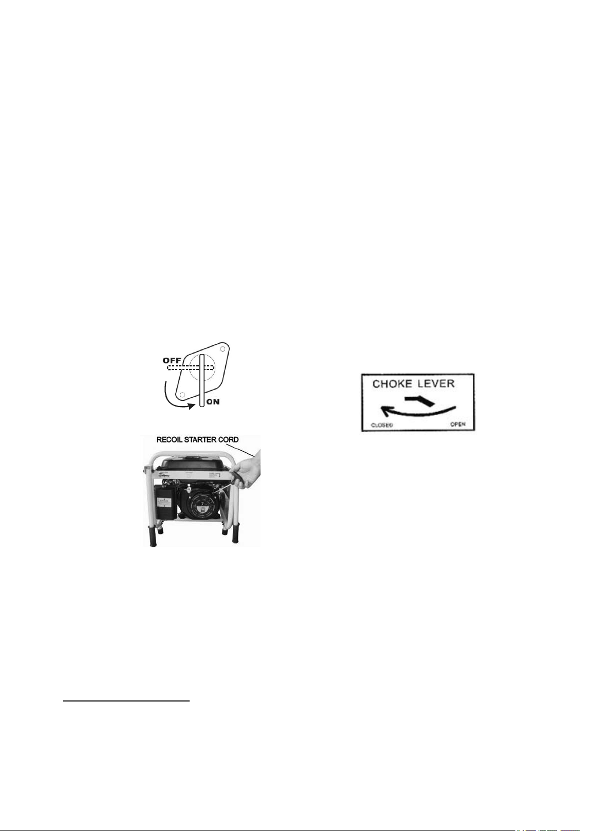
Figure 12- Fuel Valve in the “on” position
Figure 14- Pulling the start cord
Figure 13- Pull choke out for closed position.
Push `in for open position.
1. No electrical devices should be connected to the generator during starting. Devices can
make it difficult for the engine to start.
2. Check that the generator is properly grounded (see “Ground the Generator”).
3. Check the oil and fuel levels.
4. Turn the fuel valve to the “on” position (see figure 12).
5. Move the choke lever to the “closed” position (see figure 13).
6. Set the engine switch to the “on” position.
7. Pull on the recoil starter handle slowly until a slight resistance is felt (see figure 14). Then
pull quickly to start the engine. Return cord gently into the machine. Never allow the cord
to snap back.
8. If engine fails to start, repeat step 7. NOTE: After repeated failed attempts to start the
engine, please consult the troubleshooting guide before attempting again. If problems
persist please call (800) 232-1195 M-F 8-5 CST.
9. Once the engine has started, slowly return the choke lever all the way to the “open”
position.
10. Allow the generator to run for several minutes before attempting to connect any electrical
devices. This allows the generator to stabilize its speed and temperature.
SUBSEQUENT STARTING OF THE GENERATOR
If this is not the first time using the generator, user should take the following steps to prepare it for
operation.
IMPORTANT: At this point the user should be familiar with the procedures described in the
section titled “Using the Generator for the First Time.” If the user has not yet read this
section, go back and read it now.
Step 1- Check the Oil
Oil consumption is normal during generator usage. The generator is equipped with a low-oil
shutoff to protect it from damage. The oil level in the engine should be checked before each use to
ensure that the engine crankcase contains sufficient lubricant.
17
Page 22
To check or add oil, follow these steps:
1. Make sure the generator is on a level surface. Clean around oil fill.
2. Remove the oil filler/dipstick cap and check oil level.
3. If oil level is below the second thread from the lip of the oil fill opening, slowly add oil
until the engine crankcase is filled.
4. Reinstall and tighten oil filler cap before starting the engine. .
Step 2 – Check the Fuel Level
Before starting the generator, check to see that there is sufficient gasoline in the fuel tank. The fuel
gauge on top of the generator will indicate the fuel level in the tank. Add gasoline if necessary but
leave sufficient room in tank for expansion.
WARNING: This generator may emit highly
flammable and explosive gasoline vapors, which can
cause severe burns or even death if ignited. A nearby
open flame can lead to explosion even if not directly in contact with fuel.
Do not operate near open flame.
Do not smoke near generator.
Always operate on a firm, level surface.
Always turn generator off before refueling. Allow generator to cool for at least 2
minutes before removing fuel cap. Loosen cap slowly to relieve pressure in tank.
Do not overfill fuel tank. Gasoline may expand during operation. Do not fill to the
top of the tank. Allow for expansion.
Always check for spilled fuel before operating. Clean up any spilled fuel before
starting.
Empty fuel tank before storing or transporting the generator.
Before transporting, turn fuel valve to off and disconnect spark plug wire.
IMPORTANT:
Use only UNLEADED gasoline with an octane rating of 87 or higher.
Do not use old gasoline.
Never use an oil/gasoline mixture.
Avoid letting dirt or water into the fuel tank.
Step 3- Ground the Generator
WARNING: Failure to properly ground the generator can result in
electrocution.
Ground the generator by tightening the grounding nut on the front control panel against a
grounding wire. (Figure 11) A generally acceptable grounding wire is a No. 12 AWG (American
Wire Gauge) stranded copper wire. This grounding wire should be connected at the other end to a
copper or brass rod that is driven into the earth. Wire and grounding rod are not included in
generator contents.
Grounding codes can vary by location. Contact a local electrician for area codes.
18
Page 23
USING THE GENERATOR
Model Number
Rated(Running) Wattage
Surge Wattage
3500
3000
3500
WARNING: When this generator is used to supply a building wiring system:
Generator must be installed by a qualified electrician and connected to a transfer switch
as a separately derived system in accordance with the National Electrical Code, NFPA 70.
The generator shall be connected to a transfer switch that switches all conductors other than the
equipment grounding conductor. The frame of the generator shall be connected to an approved
grounding electrode.
For power outages, permanently installed stationary generators are better suited for providing
backup power to the home. Even a properly connected portable generator can become overloaded.
This may result in overheating or stressing the generator components, possibly leading to a
generator failure.
Before connecting electrical devices, allow the generator to run for a few minutes to stabilize the
speed and voltage output.
CAUTION: Become familiar with the markings on the panel before connecting electrical devices.
AC Usage
Connect electrical devices running on AC current according to their wattage requirements. The
chart in figure 15 shows the rated and surge wattage of your generator.
NOTE: Although the overall rated wattage of the machine is 3000 Watts, it is not recommended
that you attempt to draw more than 2400 Watts (20 A) from any ONE of the 120 Volt receptacles.
The rated wattage corresponds to the maximum wattage the generator can output on a continuous
basis.
The surge wattage corresponds to the maximum amount of power the generator can output for a
short period of time. Many electrical devices such as refrigerators require short bursts of extra
power, in addition to the rated wattage listed by the device, to stop and start their motors. The
surge wattage ability of the generator covers this extra power requirement.
Figure 15- generator wattage by model number.
The total running wattage requirement of the electrical devices connected to the generator should
not exceed the rated wattage of the generator itself. To calculate the total wattage requirement of
the electrical devices you wish to connect, find the rated (or running) wattage of each device. This
number should be listed somewhere on the device or in its instruction manual. If you cannot find
this wattage, you may calculate it by multiplying the Voltage requirement by the Amperage drawn:
Watts= Volts x Amperes
If these specifications are not available, you may estimate the Watts required by your device using
the chart in figure 16.
19
Page 24

When the rated wattage requirement of each electrical device has been determined, add these
tool or appliance
rated (running) Watts
additional surge Watts
electric water heater (40 gal)
4000
0
hot plate
2500
0
saw- radial arm
2000
2000
electric stove (each element)
1500-2800
0
saw- circular
1500
1500
air compressor (1 HP)
1500
3000
window air conditioner
1200
1800
saw- miter
1200
1200
microwave
1000
0
well water pump
1000
1000
reciprocating saw
960
1040
sump pump
800
1200
refrigerator freezer
800
1200
furnace blower
800
1300
computer
800
0
electric drill
600
900
television
500
0
deep freezer
500
500
garage door opener
480
0
stereo
400
0
box fan
300
600
clock radio
300
0
security system
180
0
DVD player/ VCR
100
0
common light bulb
75
0
numbers to find the total rated wattage needed. If this number exceeds the rated wattage of the
generator, DO NOT connect all these devices. Select a combination of electrical devices, which
has a total rated wattage lower than or equal to the rated wattage of the generator.
CAUTION: The generator can run at its surge wattage capacity for only a short time.
Connect electrical devices requiring a rated (running) wattage equal to or less than the rated
wattage of the generator. Never connect devices requiring a rated wattage equal to the surge
wattage of the generator. This can trip the circuit protectors (circuit breakers).
NOTE: The above wattage figures are estimates. Try to check the wattage listed on your electrical
device before consulting this chart.
Once you have determined what electrical devices you will be powering with the generator,
connect these devices according to the following procedure:
1. Plug in each electrical device with the device turned off. NOTE: Be sure to attach
appliances to the correct receptacles (outlets). Connect standard 120 Volt, single phase, 60
Hz loads only to the 120 Volt receptacles. Connect 240/120 Volt, single phase, 60Hz loads
with a NEMA L14-30 plug only to the 240/120 Volt receptacle See Figure 17 for a
depiction of each of these receptacles.
20
Figure 16- Estimated wattage requirements of common electrical devices.
Page 25
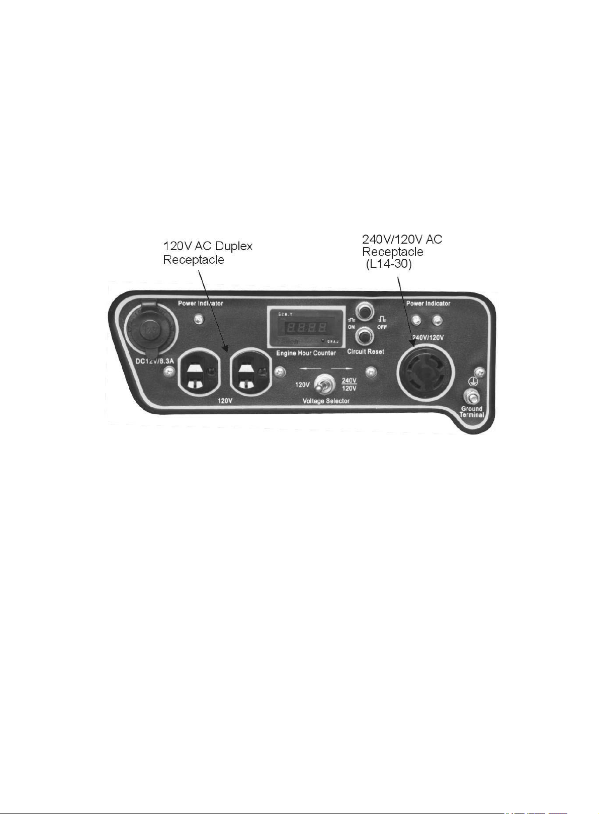
2. Push in the circuit reset buttons to the “on” position (NOTE: They may be pushed in
already).
3. Move the voltage selector to the desired position. Move the switch to the left to use the
standard 120 Volt receptacles. Move the switch to the right to use the 240/120 Volt NEMA
receptacle.
4. The power indicator lights will light accordingly as the Volt Selector is selected. They light
up when the receptacles receive power. In the case of the 240/120 Volt receptacle, both
lights MUST light up for 240/120 Volts of power. If only one light comes on, DO NOT
USE the receptacle. Press the circuit reset buttons and see if both lights come on. If both
lights will still not illuminate, call the customer service number for instructions.
CAUTION: Do not connect 50Hz or 3-phase loads to the generator.
Figure 17- Receptacles available on the generator
CIRCUIT RESET BUTTONS
The circuit reset buttons help to prevent the generator from electrical overload. If your receptacle
short circuits or becomes overloaded by an electrical device or devices with too great a wattage
rating, the circuit protector may shut off power to the receptacle. If this happens, you will see the
voltage indicator light or lights turn off and you will not be able to draw power from the
overloaded receptacle. In the event of such an overload, disconnect all electrical devices from the
generator and press the circuit reset buttons. If power still does not return to the receptacle, call
our customer service line.
SOME NOTES ABOUT POWER CORDS
Long or thin cords can drain the power provided to an electrical device by the generator. When
using such cords, allow for a slightly higher rated wattage requirement by the electrical device.
See Figure 18 for recommended cords based on the power requirement of the electrical device.
21
Page 26

Device Requirements
Max. Cord Length (ft) by Wire Gauge
Amps
Watts (120V)
Watts (240 V)
#8 wire
#10 wire
#12 wire
#14 wire
#16 wire
2.5
300
600
NR
1000
600
375
250
5
600
1200
NR
500
300
200
125
7.5
900
1800
NR
350
200
125
100
10
1200
2400
NR
250
150
100
50
15
1800
3600
NR
150
100
65
NR
20
2400
4800
175
125
75
50
NR
25
3000
6000
150
100
60
NR
NR
30
3600
7200
125
65
NR
NR
NR
40
4800
9600
90
NR
NR
NR
NR
*NR= not recommended
Figure 18- Maximum Extension Cord Lengths by Power Requirement
DC Usage
This Generator is equipped with a cigarette lighter style 12V DC receptacle. The maximum draw
for this DC outlet is 8.3 Amps. The 12V DC receptacle is not intended for use to charge
automotive batteries.
The cigarette lighter style receptacle permits the use of any electrical device designed for use in a
12V DC cigarette style outlet similar to ones found in automobiles. The electrical device has a
power cord with a metal pin on the bottom and two leaf springs on the sides. Some common
automotive type electrical devices are inflators, vacuum cleaners, chargers of various types and
more.
To Use: Simply plug the electrical device power cord into the 12V DC outlet and ensure the power
cord is securely in place. Use the device as instructed. Remove after use by simply pulling the
power cord out of the receptacle. The 12V DC receptacle is protected against overloads by an inline fuse located behind the control panel.
STOPPING THE GENERATOR
To stop the generator:
1. Turn off all electrical devices prior to unplugging them from the generator. Unplugging
running devices can cause damage to the generator.
2. Turn the engine switch to the “OFF” position.
3. Turn the fuel valve to the “OFF” (horizontal) position.
CAUTION: Allowing gasoline to sit in the generator tank for long periods of time without
use can make it difficult to start the generator in the future. Never store generator for
extended periods of time with fuel in the tank.
22
WARNING: Allow the generator to cool for several minutes before touching
areas that become hot during use.
Page 27
MAINTENANCE / CARE
Recommended Maintenance Schedule
each use
first month
then every
20 hrs
every 3
months or
50 hrs
every 6
months or
100 hrs
every year
or 300 hrs
Engine oil
check level
x
replace x
x
Air cleaner
check x
clean x
fuel filter cup
clean x
spark plug
check/ clean
x
fuel tank
check fuel level
x
clean
x
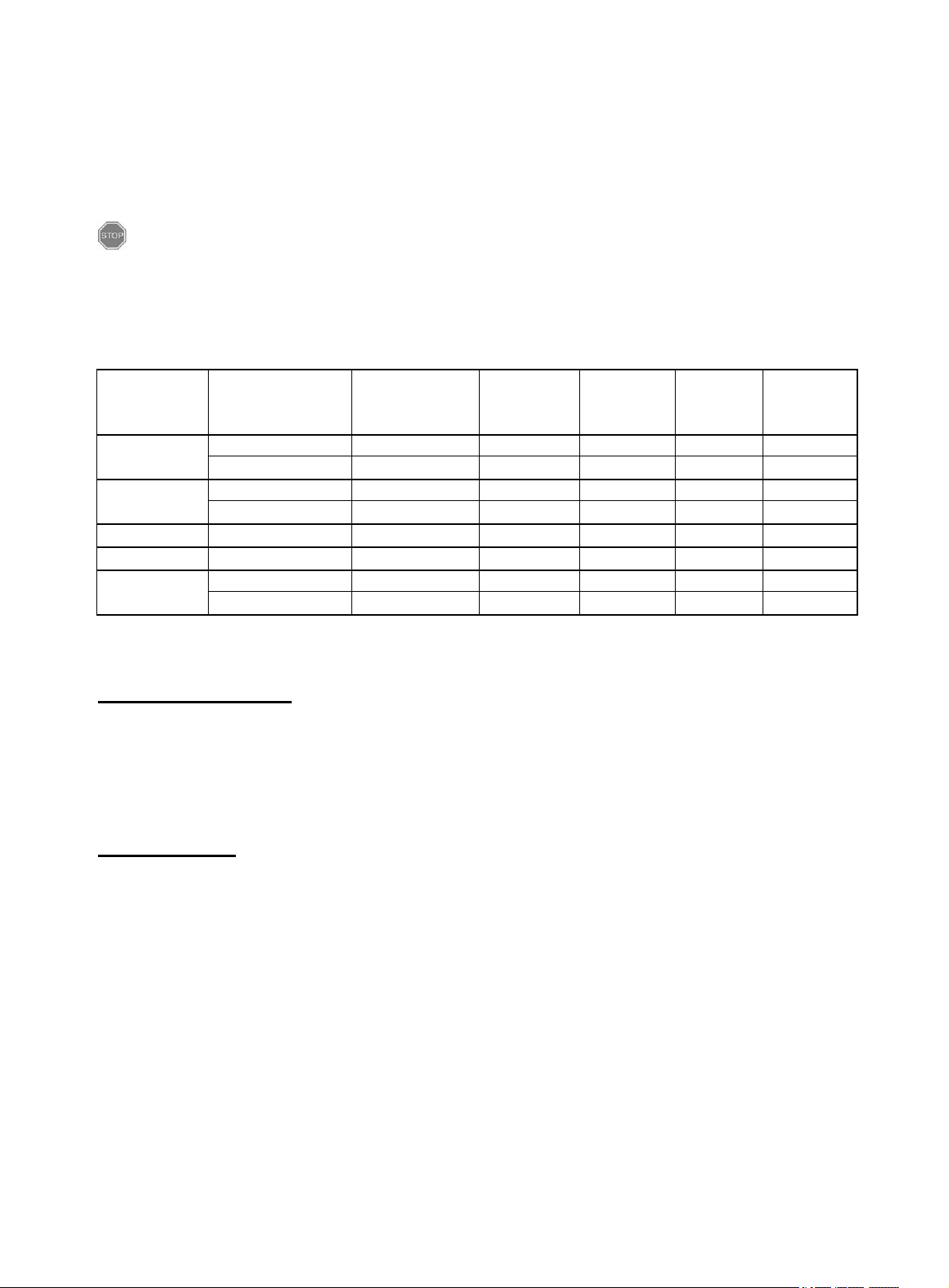
Proper routine maintenance of your generator will help prolong the life of your machine. Please
perform maintenance checks and operations according the schedule in figure 19.
If you have questions about any of the maintenance procedures listed in this manual, please
call (800) 232-1195 M-F 8-5 CST.
CAUTION: Never perform maintenance operations while the generator is running.
Figure 19- Recommended maintenance schedule
Cleaning the Generator
Never clean the generator when it is running! Never clean with a bucket of water or a hose. Water
can get inside the working parts of the generator and cause a short circuit or corrosion.
Always try to use the generator in a cool, dry place. If the generator becomes dirty, clean the
exterior with a damp cloth, a soft brush, vacuum or pressurized air.
Checking the Oil
Check the oil level of the generator according to the Recommended Maintenance Schedule in
Figure 19. The generator is equipped with an automatic shutoff to protect it from running with low
oil pressure. The generator should be checked before each use for proper oil level. This is a
critical step for proper engine starting.
To check or add oil, follow these steps:
1. Make sure the generator is on a level surface. Clean around oil fill.
2. Remove the oil filler/dipstick cap and check oil level.
3. If oil level is below the second thread from the lip of the oil fill opening, slowly add oil
until the engine crankcase is filled.
4. Reinstall and tighten oil filler cap before starting the engine. .
23
Page 28
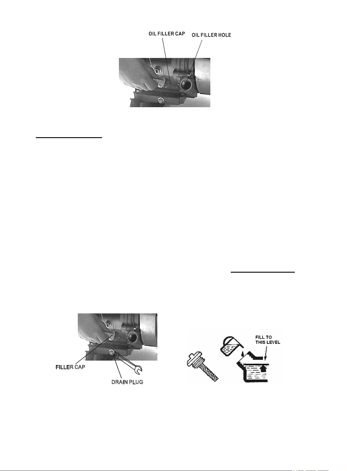
Figure 20- Checking the oil
Changing/ Adding Oil
Change the oil according to the maintenance schedule in figure 19. Change the oil when the
engine is warm. This will allow for complete drainage. Change oil more often if operating under
heavy load or high ambient temperatures. It is also necessary to drain the oil from the crankcase if
it has become contaminated with water or dirt.
The oil capacity of the engine in this generator is 20 fluid oz. Add oil when the oil level is low.
Drain the oil from the generator according to the following steps:
1. Place a container underneath the engine to catch oil as it drains.
2. Using a 10 mm hex wrench, unscrew the oil drain plug (see figure 21). Allow all the oil to
drain from the engine.
3. Reinstall the oil drain plug and tighten with a 10 mm hex wrench.
To fill the crankcase with oil, follow these steps:
1. Make sure the generator is on a level surface. Tilting the generator to assist in filling will
cause oil to flow into engine areas and will cause damage. Keep generator level!
2. Remove the oil filler/dipstick cap from the engine as shown in figure 20 above.
3. Using a funnel, add the appropriate type and amount of oil into the crankcase. The
crankcase is full when the oil level has reached the second thread from the lip of the
opening (see figure 22).
4. Check for oil leaks. Reinstall oil filler cap before starting engine.
NOTE: Never dispose of used motor oil in the trash or down a drain. Please call your local
Figure 21- Draining oil Figure 22- Adding oil
recycling center or auto garage to arrange oil disposal.
24
Page 29
Air Cleaner Maintenance
Routine maintenance of the air cleaner helps maintain proper air flow to the carburetor. Check that
the air cleaner is free of excessive dirt.
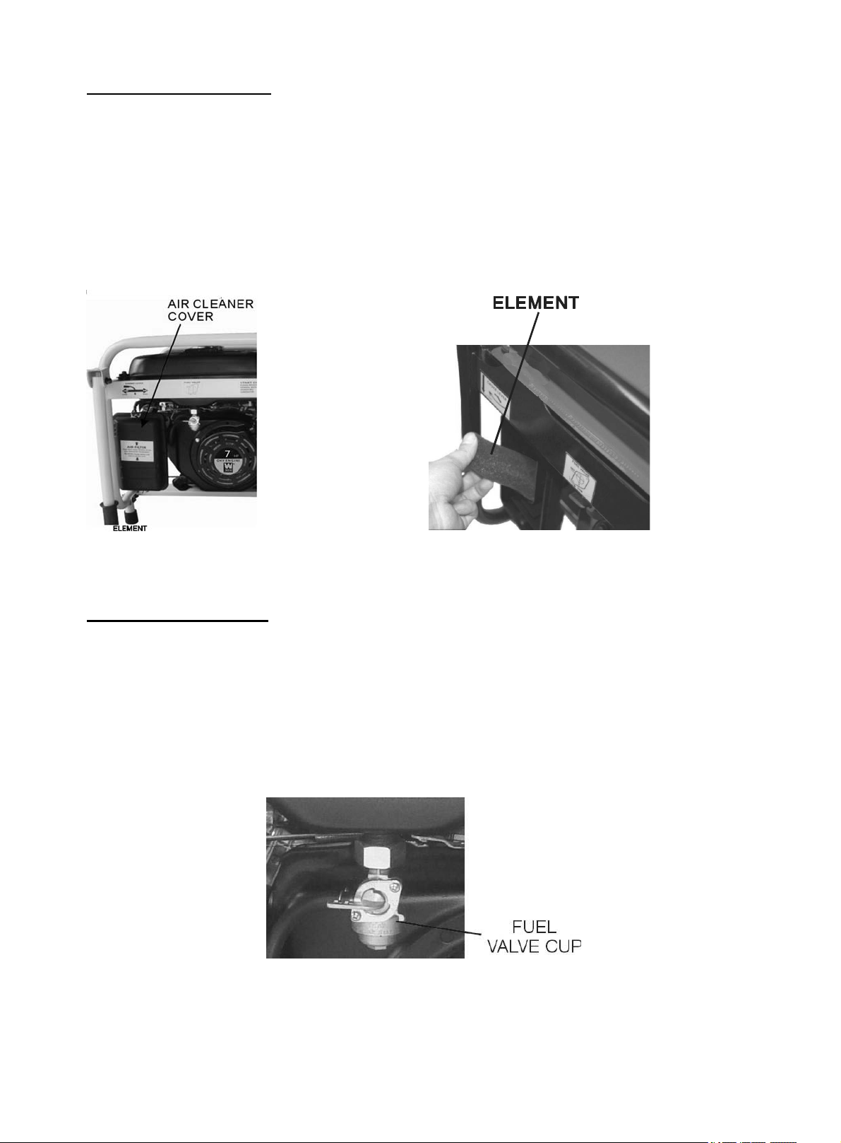
1. Unhinge the clasps at the top and bottom of the air cleaner cover (see figure 23).
2. Remove the sponge-like element from the casing.
3. Wipe the dirt from inside the empty air cleaner casing
4. Wash the sponge-like element in household detergent and warm water. Allow to dry.
5. Reinstall the sponge-like element in the air cleaner casing and reinstall the cover.
Figure 23- Removing the air cleaner casing.
Fuel Filter Cup Cleaning
The fuel filter cup is a small well underneath the fuel valve. It helps to trap dirt and water that may
be in the fuel tank before it can enter the engine. To clean the fuel filter cup:
1. Turn the fuel valve to the “off” position.
2. Unscrew the fuel filter cup from the fuel valve using a wrench. Turn the valve toward you
to unscrew (see figure 24).
3. Clean the cup of all sediment using a rag or brush.
4. Reinstall the fuel filter cup.
Figure 24- Removing the Fuel Filter Cup
25
Page 30
Spark Plug Maintenance
0.7-0.8 mm
(0.028-0.031 in)
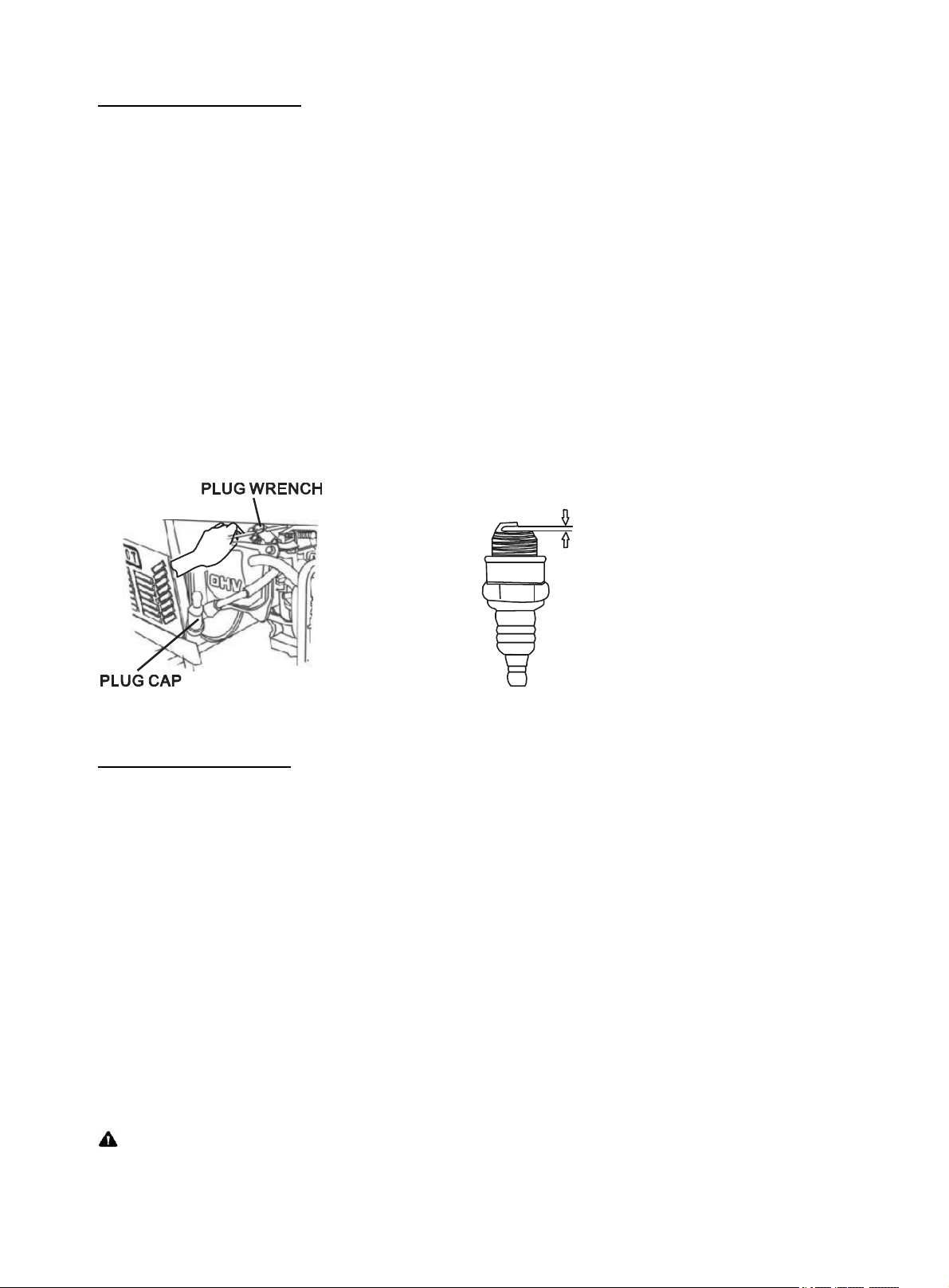
The spark plug is important for proper engine operation. A good spark plug should be intact, free
of deposits, and properly gapped. To inspect the spark plug:
1. Pull on the spark plug cap to remove it.
2. Unscrew the spark plug from the generator using the spark plug wrench included with this
product (see figure 25).
3. Visually inspect the spark plug. If it is cracked or chipped, discard and replace with a new
spark plug.
4. Measure the plug gap with a gauge (see figure 26). The gap should be 0.7-0.8mm (0.028-
0.031in).
5. If you are re-using the spark plug, use a wire brush to clean any dirt from around the spark
plug base and then re-gap the spark plug.
6. Screw the spark plug back into its place on the generator using the spark plug wrench. Do
not over-tighten spark plug. Recommended tightening of spark plug is ½ to ¾ of a turn
after spark plug gasket contacts spark plug hole. Reinstall the spark plug cap.
Figure 25- Removing the spark plug cap Figure 26- Measuring the spark plug gap
Spark plug: NGK BP7ES
Draining the Fuel Tank
Clean fuel tank each year or before storing the generator for extended periods of time. To drain the
fuel tank and carburetor:
1. Turn the fuel valve to the “off” position.
2. Remove the fuel line between the fuel valve and carburetor. Caution: a small amount of
fuel may leak from the hose during removal.
3. Attach a fuel line (not included with the generator) to exposed end of the fuel valve.
4. Position fuel line into an appropriate container and open the fuel valve allowing fuel to
flow into the container.
5. Once fuel is drained, shut off the fuel valve.
6. Start and run the engine until fuel runs out.
7. Remove the fuel filter cup (see “Fuel Filter Cup Cleaning” earlier in this section).
8. Empty the fuel filter cup of any fuel and clean
9. Reinstall the fuel filter cup.
10. Store the emptied gasoline in a suitable place.
CAUTION: Do not store fuel for more than 3 months.
26
Page 31

STORAGE / TRANSPORT PROCEDURES
CAUTION: Never place any type of storage cover on the generator
while it is still hot.
If the generator is being stored for short periods of time (30 – 60 days), add stabilized fuel to the
fuel tank until full. NOTE: Filling the tank reduces the amount of air in the tank and helps reduce
deterioration of fuel. Run the engine for 2 – 3 minutes allowing stabilized fuel mixture to
circulate through the carburetor.
When transporting or storing the generator for extended periods of time:
Drain the fuel tank (see “Draining the Fuel Tank” in the “Maintenance” section).
Disconnect the spark plug cap from the spark plug.
Do not obstruct any ventilation openings.
Keep the generator in a cool dry area.
27
Page 32
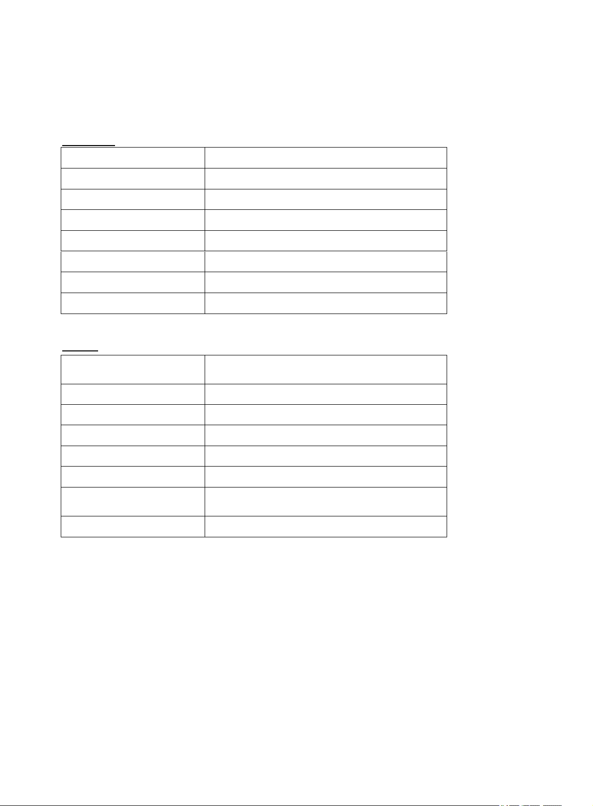
SPECIFICATIONS
Generator
AC Output
Rated Wattage
3000 W
Surge Wattage
3500 W
Rated Voltage
240V/120 V
Rated Amperage
12.5A/25A
Rated Frequency
60 Hz
Phase
Single
Dimensions(in):
length= 24.4 width= 17.7 height= 18.5
Weight
111.2 lbs
Engine
Engine type
4-stroke OHV single cylinder with forced air
cooling system
Ignition system
non-contact transistor
Displacement
208 cc
Fuel tank capacity:
15 L (4 US gal.)
Oil capacity
0.6 L (20 fl oz.)
Run time on 50% load
11 hrs
Noise rating at 22 feet
67 dB idle
74 dB fully loaded
Spark Plug
NGK BP7ES
28
Page 33
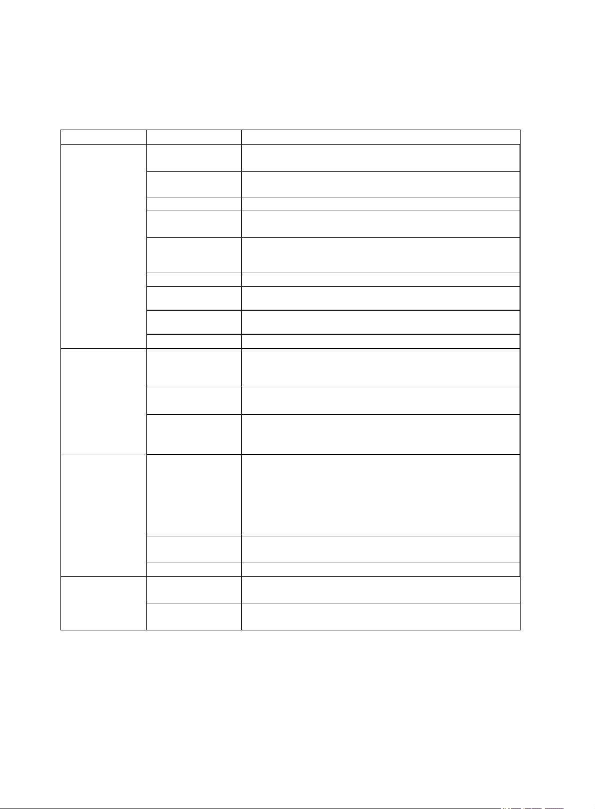
TROUBLESHOOTING
Problem
Cause
Solution
Engine will not
start
Engine switch is set
to "OFF".
Set engine switch to "ON".
Fuel valve is turned
to "OFF".
Turn fuel valve to "ON" position.
Choke is open.
Close the choke
Engine is out of fuel.
Add gasoline.
Engine is filled with
contaminated or old
gasoline.
Change the gasoline in the gas tank.
Spark plug is dirty.
Clean spark plug.
Spark plug is
broken.
Replace spark plug.
Generator is not on
level surface.
Move generator to a level surface to prevent low oil shutdown
from triggering.
Oil is low.
Add or replace oil.
Engine runs but
there is no
electrical output
Circuit reset button
is off.
Wait for 2 minutes and push the circuit reset button to the
"ON" position.
Bad connecting
wires/cables.
If you are using an extension cord, try a different one.
Bad electrical device
connected to
generator.
Try connecting a different device.
Generator runs but
does not support
all electrical
devices
connected.
Generator is
overloaded.
Perform these steps:
1. Turn off all electrical devices.
2. Unplug all electrical devices.
3. Turn off generator.
4. Wait several minutes.
5. Restart generator.
6. Try connecting fewer electrical loads to the generator.
Short in one of the
connected devices.
Try disconnecting any faulty or short-circuited electrical loads.
Air cleaner is dirty.
Clean or replace air cleaner.
DC No Power
Power cord plug not
securely in place
Twist and push power cord plug into receptacle until contact is
made with bottom of receptacle.
Protective fuse is
blown
Contact our customer service help line at (800) 232-1195.
IMPORTANT: If trouble persists please call our customer help line at (800) 232-1195 M-F 8-5
Central Time.
29
Page 34
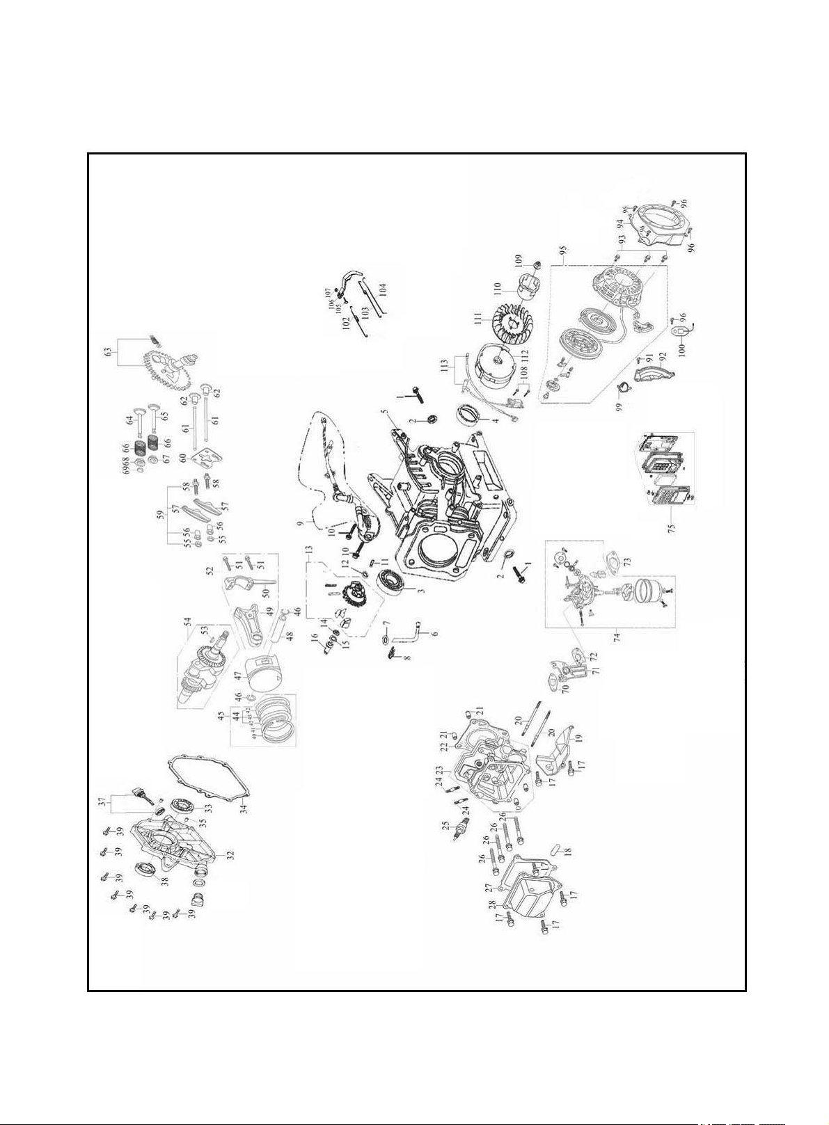
Engine exploded view
EXPLODED VIEW AND PARTS LIST
30
Page 35

Engine parts list
Item
Order #
Qty
Description
Item
Order #
Qty
Description
1
P54000
2
Oil drain plug
53
P54122
1
Woodruff key
2
P54002
2
Washer
54
P54123
1
Crankshaft assembly
3
P54004
1
Bearing 6205
55
P54128
2
Lock nut
4
P54008
1
Crankshaft oil seal
56
P54130
2
Sleeve
5
P54011
1
Crankcase
57
P54132
2
Valve rocker
6
P54014
1
Regulating sway bar
58
P54134
2
Adjusting bolt for valve gap
7
P54016
1
Washer
59
P54136
2
Valve rocker assembly
8
P54018
1
Split pin
60
P54138
1
Pusher guide
9
P54020
1
Oil sensor
61
P54140
2
Pusher
10
P54024
2
M6×14 bolt
62
P54142
2
Tappet
11
P54026
1
Regulating shaft
63
P54146
1
Camshaft assembly
12
P54028
1
Washer
64
P54150
1
Exhaust valve
13
P54031
1
Regulator gear assembly
65
P54152
1
Intake valve
14
P54032
1
Snap ring
66
P54154
2
Valve spring
15
P54034
1
Washer
67
P54156
1
Intake valve spring seat
16
P54036
1
Sleeve
68
P54158
1
Exhaust valve spring seat
17
P54040
6
M6×12 bolt
69
P54160
1
Cap
18
P54043
1
Air duct
70
P54162
1
Inlet gasket
19
P54044
1
Wind cover
71
P54164
1
Connecting block
20
P54047
2
M6×96 bolt
72
P54166
1
Carburetor gasket
21
P54048
2
Set pin 10×16
73
P54168
1
Air cleaner gasket
22
P54051
1
Cylinder head gasket
74
P54178
1
Carburetor assembly
23
P54054
1
Cylinder head Assembly
75
P54175
1
Air cleaner
24
P54058
2
M8×34 bolt
91
P54186
1
M6×22 bolt
25
P54060
1
Spark plug
92
P54596
1
Crankcase side plate assembly
26
P54062
4
Bolt
93
P54598
3
M6×8 bolt
27
P54064
1
Cylinder head cover gasket
94
P54668
1
Fan hood assembly (black)
28
P54066
1
Cylinder head cover assembly
95
P54604
1
Recoil starter (black)
32
P54075
1
Crankcase cover
96
P54040
5
M6×12 bolt
33
P54004
1
Bearing 6205
99
P54610
1
Plastic clip
34
P54080
1
Crankcase gasket
100
P54612
1
Diode
35
P54082
2
Set pin
102
P54616
1
Back spring
37
P54086
1
Oil dipstick assembly
103
P54618
1
Regulating spring
38
P54088
1
Crankshaft oil seal
104
P54620
1
Pulling rod
39
P54092
7
M8×32 bolt
105
P54622
1
Lock bolt
45
P54105
1
Piston ring assembly
106
P54624
1
Regulating arm
46
P54106
2
Piston pin clip
107
P54176
1
M6 nut
47
P54109
1
Piston
108
P54628
2
M6×25 screw
48
P54112
1
Piston pin
109
P54630
1
M14×1.5 nut
49
P54114
1
Connecting rod
110
P54632
1
Starting flange
50
P54116
1
Connecting rod cover
111
P54634
1
Flywheel fan
51
P54118
2
Bolt
112
P54636
1
Flywheel
52
P54121
1
Connecting rod assembly
113
P54638
1
Ignition coil assembly
31
Page 36
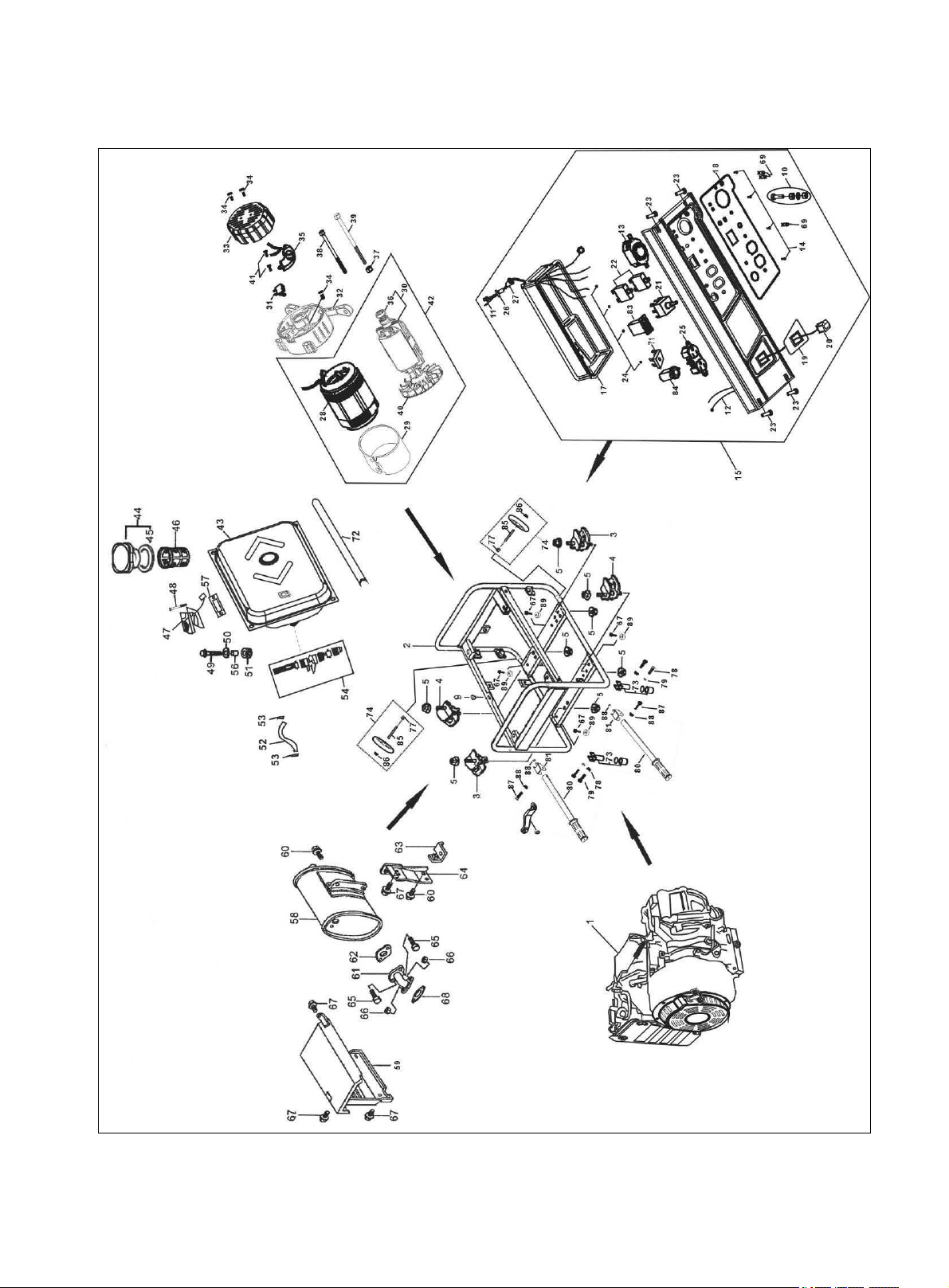
Generator exploded view
32
Page 37

Generator parts list
Item
Order #
Qty
Description
Item
Order #
Qty
Description
1
P54868
1
Gasoline engine
42
P54360
1
Stator &rotor assembly
2
P54237
1
Frame comp
43
P54369
1
Fuel tank (Black)
3
P54242
2
Bottom rubber A
44
P54368
1
Fuel cap
4
P54244
2
Bottom rubber B
46
P54372
1
Fuel filter
5
P54246
8
Flange nut M8
47
P54374
1
Fuel gauge assembly
9
P54258
1
Frame rubber pad
48
P54376
2
Screw M5×10
10
P54262
1
Earth terminal set
49
P54186
4
Flange bolt M6×22
11
P54830
1
Wire harness assembly
50
P54384
4
Washer
12
P54831
1
Switch wire
51
P54386
4
Cushion
13
P54272
1
Receptacle(30A)
52
P54388
1
Outlet pipe φ 9×φ 4.5×130
14
P54276
4
Bolt M4×10
53
P54390
2
Tube clip
15
P54283
1
Control panel assembly
54
P54392
1
Fuel cock
17
P54834
1
Control panel case
56
P54396
4
Fitting brush, fuel tank
18
P54291
1
Panel switch mark, RH
58
P54401
1
Muffler
19
P54293
1
Panel switch mark, LH
59
P54402
1
Muffler guard
20
P54296
1
Ignition switch
60
P54404
3
Flange bolt M8×16
21
P54826
1
Voltage selector
61
P54406
1
Exhaust pipe comp
22
P54838
2
Circuit breaker(13A)
62
P54408
1
Muffler gasket
23
P54304
4
Circuit bolt M6×25
63
P54410
1
Supporting plate
24
P54308
4
Nut M4
64
P54412
1
Muffler stay
25
P54454
1
Duplex receptacle
65
P54414
2
Bolt M8×25
26
P54316
1
AC output wire boot
66
P54246
2
Nut M8
27
P54318
1
Main wire harness boot
67
P54422
10
Flange bolt M6×12
28
P54325
1
Stator assembly
68
P54426
1
Exhaust pipe gasket
29
P54324
1
Stator cover
69
P54828
3
Power indicator
30
P54329
1
Rotor comp
71
P54451
1
Rectifier
31
P54332
1
Brush assembly
72
P54870
1
Decorating stripe, fuel tank
32
P54336
1
Generator stay
73
P54871
2
Rubber foot assembly
33
P54337
1
Generator end cover (Black)
74
P54872
2
Wheel assembly
34
P54340
3
Bolt M5×12
77
P54873
2
Nut
35
P54342
1
Voltage regulator
78
P54874
4
Bolt M6×40
36
P54346
1
Bearing 6202-2RS
79
P54875
4
Nut M6
37
P54348
1
Plain washer
80
P54876
2
Handle assembly
38
P54350
4
Flange bolt M6×160
83
P54877
1
Engine hour counter (E)
39
P54354
1
Bolt M8×210
84
P54878
1
12V Cigarette lighter style DC
receptacle
40
P54358
1
Generator fan
85
P54879
2
Wheel shaft assembly
41
P54360
3
Bolt M5×14
89
P54254
4
Rubber bottom
33
Page 38
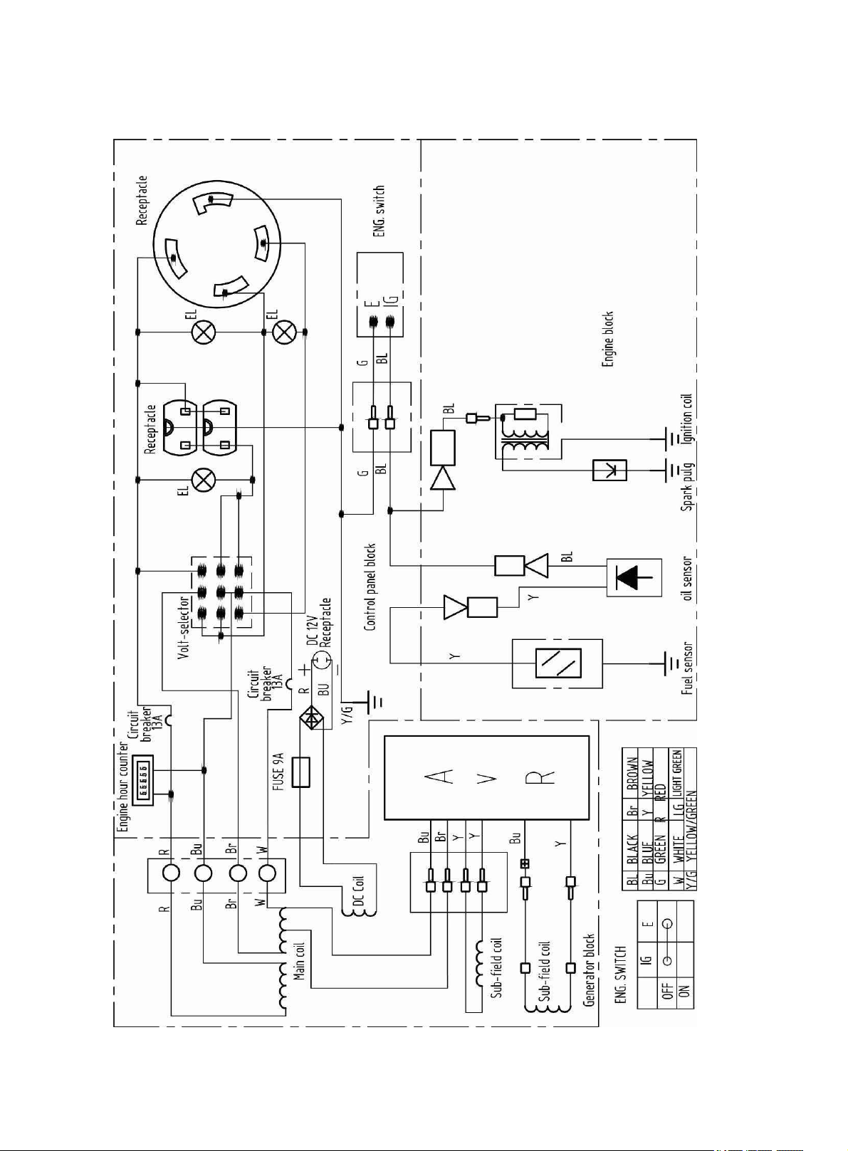
WIRING DIAGRAM
34
Page 39

NOTES:
35
Page 40

WARRANTY STATEMENT
WEN Power™ generators are warranted (to the original purchaser) to be free from defects
in materials and workmanship for a period of two (2) years from the date of original
purchase. Generators used for commercial or for rental have a warranty period of 90 days
from date of original purchase. Please fill out and mail the enclosed warranty card and mail
it to Power Pro Technology along with a copy of the receipt. The information is required to
process warranty claims.
WEN Power™ will repair or replace, at its discretion, any part that is proven to be
defective in materials or workmanship under normal use during the two (2) year warranty
period. Warranty repairs or replacements will be made without charge for parts or labor.
Parts replaced during warranty repairs will be considered as part of the original product
and will have the same warranty period as the original product.
TO EXERCISE WARRANTY COVERAGE:
Do not return to retailer! For warranty and technical support call the toll-free
Customer Service Number: (800) 232-1195 and you will be informed of the nearest
authorized service center. We will prearrange the repair with the center.
WARRANTY COVERAGE:
This warranty is conveyed to the original purchaser and is not transferable.
Generators contain parts that will wear out with usage and parts that need maintenance.
The warranty does not cover wear or maintenance parts. Specifically, the warranty does
not cover replacement of air filter, spark plug, brush and recoil starter rope.
Warranty does not extend to generators damaged or affected by accidents, neglect, misuse,
contaminated fuel, unauthorized alterations, use in applications beyond product design and
any other modification or abuse.
WEN Power™ is not liable for any indirect, incidental or consequential damages from the
sale or use of this product. Any implied warranties are limited to two (2) years as stated in
this written limited warranty. Some states do not allow limitation on the length of an
implied warranty. Some states do not allow the exclusion or limitation of incidental or
consequential damages. This warranty gives you the specific legal right, and you may have
other rights that vary by state.
FOR WEN POWERTM GENERATORS
Wen Power
36
TM
. Elgin, IL 60123. www.wenproducts.com.
 Loading...