

Page 1
2000W INVERTER
GENERATOR
Model # 56200i
bit.ly/WENvideo
IMPORTANT:
Your new tool has been engineered and manufactured to WEN’s highest standards for dependability,
ease of operation, and operator safety. When properly cared for, this product will supply you years
of rugged, trouble-free performance. Pay close attention to the rules for safe operation, warnings,
and cautions. If you use your tool properly and for intended purpose, you will enjoy years of safe,
reliable service.
NEED HELP? CONTACT US!
Have product questions? Need technical support?
Please feel free to contact us at:
800-232-1195
(M-F 8AM-5PM CST)
techsupport@wenproducts.com
WENPRODUCTS.COM
Page 2

TABLE OF CONTENTS
Generator Identification
Service Record
Introduction
Safety Information
General Safety Procedures
Important Safety Instructions
Generator Components
Generator Preperation
Starting the Generator
Stopping the Generator
Subsequent Starting of the Generator
Using the Generator
Maintenance & Care
Storage & Transport
Specifications
Troubleshooting
Exploded View and Parts List
Wiring Diagram
Warranty Statement
3
3
4
4
5
6
7
8
10
12
12
14
16
20
21
22
23
29
30
2
Page 3
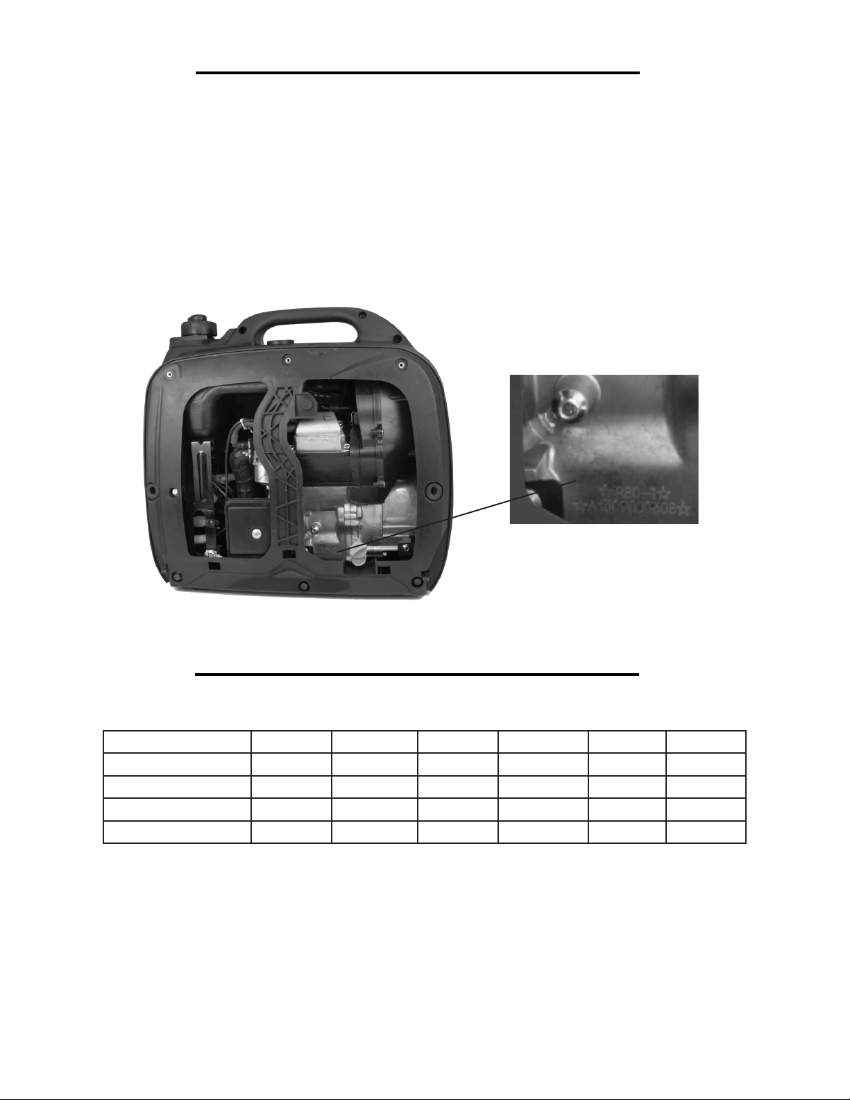
GENERATOR IDENTIFICATION
If assistance for information or service is required, please contact the Customer Service Help Line by calling
800-232-1195; customer will be asked to provide generator information when calling.
Refer to the illustration below for the location of the serial number. Record generator information in the spaces
provided below.
DATE OF PURCHASE: ______________________________________________
PURCHASED FROM: ______________________________________________
GENERATOR MODEL NUMBER: ____________________________________
ENGINE SERIAL NUMBER: _________________________________________
Change Oil
Change Spark Plug
Clean Fuel Tank
Clean Air Cleaner
SERVICE RECORD
Record Service Dates:
Date Date Date Date Date Date
3
Page 4
INTRODUCTION
Thank You for Purchasing a WEN® Product. This manual provides information regarding the safe operation
and maintenance of this product. Every effort has been made to ensure the accuracy of the information in this
manual. WEN® reserves the right to change this product and specifications at any time without prior notice.
Please keep this manual available to all users during the entire life of the generator.
This manual contains special messages to bring attention to potential safety concerns, generator damage as well as helpful operating and servicing information. Please read all the
information carefully to avoid injury and machine damage.
QUESTIONS? PROBLEMS?
In order to answer questions and solve problems in the most efficient and speedy manner, contact Customer
Service at (800) 232-1195, M-F 8-5 CST
NOTICE REGARDING EMISSIONS
Engines that are certified to comply with U.S. EPA emission regulations for SORE (Small Off Road Equipment),
are certified to operate on regular unleaded gasoline, and may include the following emission control systems:
(EM) Engine Modifications and (TWC) Three-Way Catalyst (if so equipped).
SAFETY INFORMATION
Before operating this generator read and observe all warnings, cautions, and instructions on the generator and in
this Owner’s Manual.
NOTE: The following safety information is not meant to cover all possible conditions and situations that may occur. Read the entire Owner’s Manual for safety and operating instructions. Failure to follow instructions and safety
information could result in serious injury or death.
This safety alert symbol is used to identify safety information about hazards that can result in personal injury.
A signal word (DANGER, WARNING, or CAUTION) is used with the alert symbol to indicate the
likelihood and the potential severity of injury. In addition, a hazard symbol may be used to represent
the type of hazard.
DANGER indicates a hazard, which, if not avoided, will result in death or serious injury.
WARNING indicates a hazard, which, if not avoided, could result in death or serious injury.
CAUTION indicates a hazard, which, if not avoided, might result in minor or moderate injury.
CAUTION when used without the alert symbol, indicates a situation that could result in damage to the engine or
generator.
4
Page 5

GENERAL SAFETY PROCEDURES
For any questions regarding the hazard and safety notices listed in this manual or on the product, please call (800)
232-1195 M-F 8-5 CST before using the generator.
DANGER: CARBON MONOXIDE
Using a generator indoors CAN KILL YOU IN MINUTES. Generator exhaust contains carbon monoxide (CO).
This is a poison gas you cannot see or smell. If you can smell the generator exhaust, you are breathing CO. But
even if you cannot smell the exhaust, you could be breathing CO.
NEVER use a generator inside homes, garages, crawlspaces, or other partly enclosed areas. Deadly levels
of carbon monoxide can build up in these areas. Using a fan or opening windows and doors does NOT
supply enough fresh air. ONLY use a generator outside and far away from windows, doors, and vents. These openings can pull in generator exhaust.
Even if you use a generator correctly, CO may leak into the home. ALWAYS use a battery-powered or batterybackup CO alarm in the home. If you start to feel sick, dizzy, or weak after the generator has been running, move
to fresh air RIGHT AWAY. See a doctor. You may have carbon monoxide poisoning.
WARNING: The exhaust from this product contains chemicals known to the State of California to cause
cancer, birth defects, or other reproductive harm.
WARNING: This generator may emit highly flammable and explosive gasoline vapors, which can cause
severe burns or even death if ignited. A nearby open flame can lead to explosion even if it isn’t directly in
contact with gasoline.
• Do not operate near open flame.
• Do not smoke near generator.
• Always operate on a firm, level surface.
• Always turn generator off before refueling. Allow generator to cool for at least 2 minutes before removing
fuel cap. Loosen cap slowly to relieve pressure in tank.
• Do not overfill fuel tank. Gasoline may expand during operation. Do not fill to the top of the tank. Allow
for expansion.
• Always check for spilled fuel before operating.
• Empty fuel tank before storing or transporting the generator.
WARNING: This generator produces powerful voltage, which can result in electrocution.
• ALWAYS ground the generator before using it (see the “Ground the Generator” portion of the
“GENERATOR PREPARATION” section).
• Generator should only be plugged into electrical devices, either directly or with an extension cord.
NEVER connect to a building electrical system without a qualified electrician. Such connections must
comply with local electrical laws and codes. Failure to comply can create a back-feed, which may result
in serious injury or death to utility workers.
• Use a ground fault circuit interrupter (GFCI) in highly conductive areas such as metal decking or steel
work. GFCIs are available in-line with some extension cords.
• Do not use in rainy conditions.
• Do not touch bare wires or receptacles (outlets).
• Do not allow children or non-qualified persons to operate.
5
Page 6

GENERAL SAFETY PROCEDURES
WARNING: This generator produces heat when running. Temperatures near exhaust can exceed 1500
F (650 C).
Do not touch hot surfaces. Pay attention to warning labels on the generator identifying hot parts of the
machine.
Allow generator to cool down after use before touching engine or areas of the generator that become
hot during use.
CAUTION: Misuse of this generator can damage it or shorten its life.
Only use generator for its intended purposes.
Operate only on dry, level surfaces.
Allow generator to run for several minutes before connecting electrical devices.
Shut off and disconnect any malfunctioning devices from generator.
Do not exceed the wattage capacity of the generator by plugging in more electrical devices than the unit can
handle.
Do not turn on electrical devices until after they are connected to the generator.
Turn off all connected electrical devices before stopping the generator.
Turn the engine switch to “OFF” position when the engine is not running.
IMPORTANT SAFETY INSTRUCTIONS
SAVE THESE INSTRUCTIONS – This manual contains important instructions for the WEN® 2000W inverter
generator that should be followed during installation and maintenance of the generator.
Generators vibrate in normal use. During and after the use of the generator, inspect botht he generator as well as
extension and power supply cords for damage resulting from vibration. Have damaged items repaired or replaced
as necessary. Do not use plugs or cords that show signs of damage such as broken or cracked insulation or damaged blades.
For power outages, permanently installed stationary generators are better suited for providing backup power to the
home. Even a properly connected portable generator can become overloaded. This may result in overheating or
stressing of the components, possibly leading to a generator failure.
WARNING: If this generator is used as a supply for a building’s wiring system, the generator must be installed
by a qualified electrician and connected to a transfer switch as a separately derived system in accordance with
the National Electrical Code, NFPA 70. The generator shall be connected to a transfer switch that switches all
conductors excluding the equipment grounding conductor. The frame of the generator shall be connected to an
approved grounding electrode.
6
Page 7
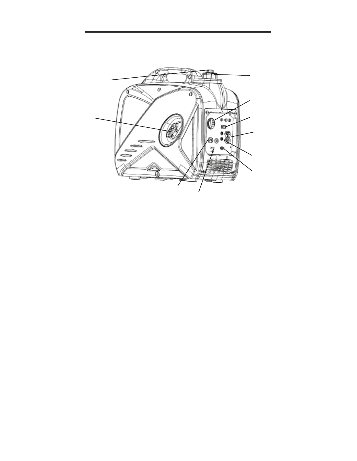
GENERATOR COMPONENTS
Use the illustrations below to become familiar with the locations and functions of the various components and
controls of this generator.
Vacuum Relief Valve
Recoil Starter
Fuel Cap
3-in-1 Switch
Idle Switch
120V Duplex Receptacle
Circuit Breaker
Grounding Nut
12V DC Outlet
USB Charger
7
Page 8
GENERATOR PREPARATION
USING THE GENERATOR FOR THE FIRST TIME
The following section describes steps necessary to prepare the generator for use. If after reading this section, you are unsure about how to perform any of the steps please call (800) 232-1195 M-F 8-5 CST for
customer service. Failure to perform these steps properly can damage the generator or shorten its life.
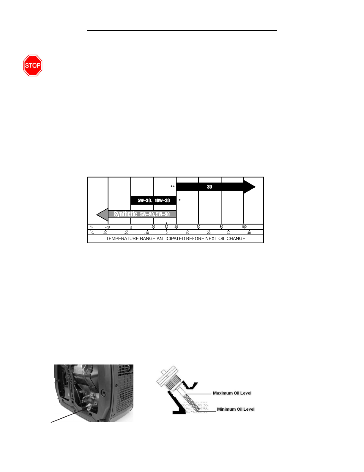
Step 1 - ADD OIL
The generator is shipped without oil. User must add the proper amount of oil before operating the generator for
the first time. The oil capacity of the engine crankcase is 0.37 quarts (0.35 liters). For general use (above 40° F),
we recommend 30W, 4-stroke engine oil.
ENGINE OIL RECOMMENDATIONS
Select good quality detergent oil bearing the American Petroleum Institute (API) service classifications SJ, SL,
or SM. (Synthetic oils may be used.) Use the ASE viscosity grade of oil from the following chart (Figure 1) that
matches the starting temperature anticipated before the next oil changes.
Figure 1 - Engine Oil Replacemendations
To add oil, follow these steps:
1. Make sure the generator is on a level surface. Tilting the generator to assist in filling will cause oil to flow
into engine areas and will cause damage. Keep generator level!
2. Open the access panel. Remove the dipstick from the engine. (Figure 2)
3. Add oil slowly to bring level to full. (Figure 2).
4. To check the oil level: wipe the dipstick with a clean rag. Insert the dipstick into the oil fill opening
without screwing in. Remove the dipstick to check the oil mark.
5. Slowly add more oil and repeat step 4 until the oil mark reaches to the top of the dipstick (Figure 2). Do
not over fill the crankcase. The generator is equipped with a low oil sensor and will not start if the amount
of oil is in sufficient.
6. Check for oil leaks. Tighten dipstick firmly before closing the access panel.
Oil Dipstick Figure 2 - Oil Fill Opening, Dipstick and Oil Level
88
Page 9
GENERATOR PREPARATION
Step 2 - ADD GASOLINE
WARNING: This generator may emit highly ammable and explosive gasoline vapors,
which can cause severe burns or even death if ignited. A nearby open ame can lead to
explosion even if not directly in contact with gasoline.
Use fresh (within 30 days from purchase), lead-free gasoline with a minimum of 87 octane rating. Do not mix oil
with gasoline.
To add gasoline, follow these steps:
1. Make sure the generator is on a level surface.
2. Unscrew fuel cap and set aside. NOTE: The fuel cap may be tight and hard to unscrew.
3. Slowly add unleaded gasoline to the fuel tank. Be careful not to overfill. The capacity of the fuel tank is 1
gallon. NOTE: Do not fill the fuel tank to the very top. Gasoline will expand and spill over during use even
with the fuel cap in place.
4. Reinstall fuel cap and wipe clean any spilled gasoline with a dry cloth.
IMPORTANT:
• Never use an oil/gasoline mixture.
• Never use old gasoline.
• Avoid getting dirt or water into the fuel tank.
• Gasoline can age in the tank and make starting difficult. Never store generator for extended periods of time
with fuel in the tank.
Step 3 - GROUND THE GENERATOR
WARNING: Failure to properly ground the generator
can result in electrocution.
Ground the generator by tightening the grounding nut on the
front control panel against a grounding wire (Figure 3). A generally acceptable grounding wire is a No. 12 AWG (American Wire
Gauge) stranded copper wire. This grounding wire should be
connected at the other end to a copper, brass, or steel-grounding
rod that is driven into the earth. Wire and grounding rods are not
included in generator contents.
Grounding codes can vary by location. Contact a local electrician
to check the area codes.
Figure 3 - Grounding Nut
NOTE: After completing the above preparation, the generator is ready to be started.
9
Page 10

STARTING THE GENERATOR
Before starting the generator, make sure you have read and performed the steps in the “Generator Preperation”
section of this manual. If you are unsure about how to perform any of the steps in this manual please call (800)
232-1195 M-F 8-5 CST for customer service.
DANGER: CARBON MONOXIDE.
Using a generator indoors CAN KILL YOU IN MINUTES.
Generator exhaust contains carbon monoxide (CO). This is a poison gas you cannot see or smell. If you can
smell the generator exhaust, you are breathing CO. Even if you cannot smell the exhaust, you may be breathing CO.
NEVER use a generator inside homes, garages, crawlspaces, or other partly enclosed areas. Deadly levels of
carbon monoxide can build up in these areas. Using a fan or opening windows and doors does NOT supply
enough fresh air.
ONLY use a generator outside and far away from windows, doors, and vents. These openings can pull in
generator exhaust. Even if you use a generator correctly, CO may leak into the home. ALWAYS use a batterypowered or battery-backup CO alarm in the home.
If you start to feel sick, dizzy, or weak after the generator has been running, move to fresh air RIGHT AWAY.
See a doctor. You may have carbon monoxide poisoning.
WARNING: This generator produces powerful voltage, which can result in electrocution.
ALWAYS ground the generator before using it (see the “Ground the Generator” portion of the “Generator
Preperation” section).
- Generator should only be plugged into electrical devices, either directly or with an extension cord. NEVER
connect to a building electrical system without a qualified electrician. Such connections must comply with local
electrical laws and codes. Failure to comply can create a back-feed, which may result in serious injury or death
to utility workers.
- Use a ground fault circuit interrupter (GFCI) in highly conductive areas such as metal decking or steel work.
GFCIs are available in-line with some extension cords.
- Do not use in rainy or wet conditions.
- Do not touch bare wires or receptacles (outlets).
- Do not allow children or non-qualified persons to operate.
CAUTION: Disconnect all electrical loads from the generator before attempting to start.
10
Page 11

STARTING THE GENERATOR
STARTING THE ENGINE
To start the generator, perform the following steps:
1. Unplug all electrical devices from the generator during starting. Otherwise it can be difficult for the engine to
start.
2. Check that the generator is properly grounded (Refer to “Ground the Generator”).
3. Check the oil and fuel levels.
4. Turn the ESC switch to “OFF.”
5. Open vacuum relief valve on top of fuel cap (Figure 4). Rotate clockwise to the “ON” position.
6. Turn the 3-in-1 switch to the “CHOKE” position.
7. Pull on the recoil starter handle slowly until a slight resistance is felt, then pull quickly to start the engine.
Return cord gently into the recoil starter. Never allow the cord to snap back.
8. Once the engine has started, slowly turn the 3-in-1 switch to the “ON” position.
Allow the generator to run for several minutes before attempting to connect any electrical devices. This allows
the generator to stabilize its speed and temperature.
Figure 4 - Fuel Cap & Fuel Valve
11
Page 12

STARTING THE GENERATOR
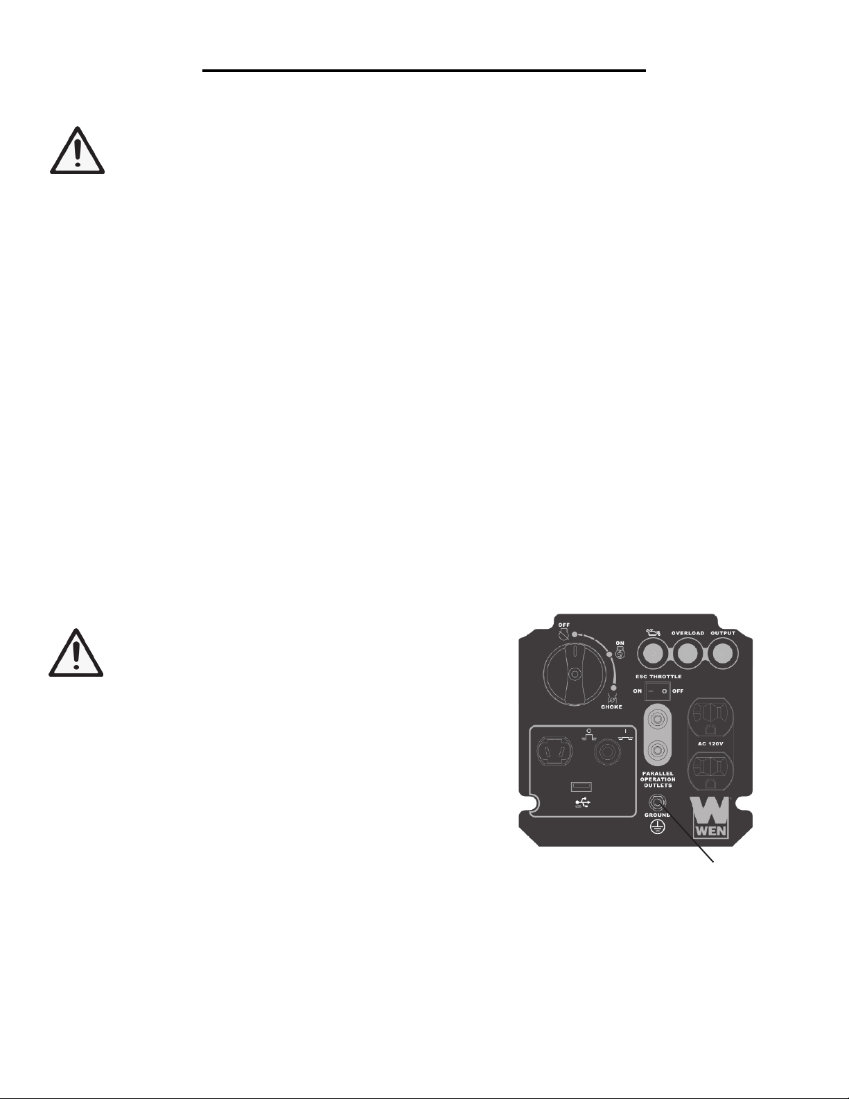
IDLE CONTROL SWITCH (ESC)
This generator is equipped with an Idle Control Switch. Engaging the switch will automatically adjust the engine speed.
When an electrical device comes on line, the generator engine will automatically speed up to supply the power needed
and will slow down as the need decreases. The variable
engine speed can reduce fuel consumption and noise level.
Keep this switch engaged when the power load requirement
is less than 1000W. Do not engage the Idle Control Switch
when the total load is more than 1000W. The generator
engine must run at full speed to supply the required power
for anything over 1000W.
Figure 5 - Control Panel
STOPPING THE GENERATOR
TO STOP THE GENERATOR
1. Turn off all electrical devices prior to unplugging them from the generator. Unplugging running devices
can cause damage to the generator.
2. Turn the 3-in-1 knob to the “OFF” position.
3. Close the vacuum relief valve on top of fuel cap. Rotate counterclockwise to the “OFF” position.
Idle control
switch
WARNING: Allow the generator to cool for several minutes before touching areas that become hot during use.
CAUTION: Allowing gasoline to sit in the fuel tank for long periods of time can make it difficult to start the
generator in the future. Never store the generator for extended periods of time with fuel in the fuel tank. Refer to
Generator Storage Section.
SUBSEQUENT STARTING OF THE GENERATOR
If this is not the first time using the generator, the user should take the following steps to prepare it for operation.
IMPORTANT: At this point the user should be familiar with the procedures described in
the section titled “Using the Generator for the First Time.” If the user has not yet read
this section, go back and read it now.
Step 1 - CHECK THE OIL
Oil consumption is normal during generator use. The generator is equipped with a low oil pressure shutoff to
protect it from damage. The oil level of the engine should be checked before each use to ensure that the engine
crankcase contains sufficient lubricant.
12
Page 13

SUBSEQUENT STARTING OF THE GENERATOR
To check or add oil, follow these steps:
1. Place the generator on a level surface.
2. Open access panel. Clean around oil fill hole. Remove dipstick and wipe the dipstick with a clean rag. Insert the dipstick into the oil fill opening without screwing in. Remove the dipstick to check the oil mark. Add
oil if the oil mark covers less than one half of the dipstick.
3. Slowly add more oil and repeat step 2 until the oil mark reaches to the top of dipstick (Figure 2). Do not
over fill the crankcase.
4. Tighten dipstick firmly then put back access panel before starting the engine.
Step 2 - CHECK THE FUEL LEVEL
Before starting the generator, check to see that there is sufficient gasoline in the fuel tank. Add additional gasoline
as necessary but leave sufficient room in tank for expansion.
WARNING: This generator may emit highly flammable and explosive gasoline vapors, which can cause
severe burns or even death if ignited. A nearby open flame can lead to explosion even if not directly in
contact with fuel.
• Do not operate near open flame.
• Do not smoke near generator.
• Always operate on a firm, level surface.
• Always turn generator off before refueling. Allow generator to cool for at least 2 minutes before removing
fuel cap. Loosen cap slowly to relieve pressure in tank.
• Do not overfill fuel tank. Gasoline may expand during operation. Do not fill to the top of the tank. Allow
for expansion.
• Always check for spilled fuel before operating. Clean up any spilled fuel before starting.
• Empty fuel tank before storing or transporting the generator.
• Before transporting, turn fuel valve to off position.
IMPORTANT:
• Use only UNLEADED gasoline.
• Do not use old gasoline.
• Never use an oil/gasoline mixture.
• Avoid getting dirt or water into the fuel tank.
Step 3 - GROUND THE GENERATOR
WARNING: Failure to properly ground the generator can result in electrocution.
Ground the generator by tightening the grounding nut on the front control panel against a grounding wire (Figure
3). A generally acceptable grounding wire is a No. 12 AWG (American Wire Gauge) stranded copper wire. This
grounding wire should be connected at the other end to a copper, brass, or steel-grounding rod that is driven into
the earth. Wire and grounding rod are not included in generator contents.
Grounding codes can vary by location. Contact a local electrician for area codes.
13
Page 14

USING THE GENERATOR
WARNING: When this generator is used on a building’s wiring system, the generator must be installed by a qualified electrician and connected to a transfer switch as a separately derived system in accordance with the National
Electrical Code, NFPA 70. The generator shall be connected to a transfer switch that switches all conductors
other than the equipment grounding conductor. The frame of the generator shall be connected to an approved
grounding electrode.
For power outages, permanently installed stationary generators are better suited for providing backup power to the
home. Even a properly connected portable generator can become overloaded. This may result in overheating or
stressing the machine’s components, possibly leading to a generator failure.
Before connecting electrical devices, allow the generator to run for a few minutes to stabilize the speed and voltage
output.
CAUTION: Become familiar with the markings on the panel before connecting electrical devices.
Connect electrical devices running on AC current according to their wattage requirements. The chart in Figure 6
shows the rated and surge wattage of the generator.
The rated (running) wattage is the wattage the generator can produce on a continuous basis.
The surge wattage is the maximum amount of power the generator can produce for an extremely short period of
time (seconds). Many electrical devices such as refrigerators require short bursts of extra power in addition to the
rated wattage listed by the device to start their motors. The surge wattage ability of the generator covers this extra
power requirement.
Item Rated (Running) Wattage Surge Wattage
56200i 1600 2000
Figure 6 - Generator Wattage
The total running wattage requirement of the electrical devices connected to the generator should not exceed the
rated wattage of the generator itself. To calculate the total wattage requirement of the electrical devices you plan
to connect, find the rated (or running) wattage of each device. This number should be listed somewhere on the
device or in its instruction manual. If this wattage cannot be found, calculate it by multiplying the Voltage requirement by the Amperage drawn:
Watts = Volts x Amperes
If these specifications are not available, estimate the watts requirement of the device by using the chart in Figure 7.
When the rated wattage requirement of each electrical device has been determined, add these numbers to find
the total rated wattage needed. If this number exceeds the rated wattage of the generator, DO NOT connect all
these devices. Select a combination of electrical devices, which have a total rated wattage lower than or equal to
the rated wattage of the generator.
14
Page 15

USING THE GENERATOR
CAUTION: The generator can run at its surge wattage capacity for only a short time. Connect electrical devices
requiring a rated (running) wattage equal to or less than the rated wattage of the generator. Never connect devices
requiring a rated wattage equal to the surge wattage of the generator. This can trip the circuit protectors (circuit
breakers).
Tool or Appliance Rated (Running) Watts ADDITIONAL SURGE WATTS
Electric water heater (40 Gal) 4000 0
Hot plate 2500 0
Saw - radial arm 2000 2000
Electric stove (each element) 1500-2800 0
Saw - circular 1500 1500
Air compressor (1 HP) 1500 3000
Window air conditioner 1200 1800
Saw - miter 1200 1200
Microwave 1000 0
Well water pump 1000 1000
Saw - reciprocating 960 1040
Sump pump 800 1200
Refrigerator freezer 800 1200
Furnace blower 800 1300
Computer 800 0
Electric drill 600 900
Television 500 0
Deep freezer 500 500
Garage door opener 480 0
Stereo 400 0
Box fan 300 600
Clock radio 300 0
Security system 180 0
DVD player / VCR 100 0
Common light bulb 75 0
Figure 7- Estimated wattage requirements of common electrical devices
Note: The above wattage figures are estimates. Check the wattage listed on the electrical device before consulting
this chart. Once the electrical devices that will be powered by the generator have been determined, connect these
devices according to the following procedure:
1. Plug in each electrical device, making sure that the device is turned off.
2. Check the overload light and power indicator light. If the overload light is on, remove the plugged in load, then
press the power reset button before plugging the loads back in. If the reset button does not reset, wait several minutes and try again. If the power light still does not come on, call the customer service number for further instructions.
15
Page 16

USING THE GENERATOR
CAUTION: Do not connect 50Hz loads to the generator.
SOME NOTES ABOUT POWER CORDS
Long or thin cords can drain the power provided to an electrical device by the generator. When using such cords,
allow for a slightly higher rated wattage requirement by the electrical device. See Figure 8 for recommended
cords based on the power requirement of the electrical device.
Device Requirements
Amps Watts (120V) #8 wire #10 wire #12 wire #14 wire #16 wire
2.5 300 NR NR NR 375 250
5 600 NR NR 300 200 125
7.5 900 NR 350 200 125 100
10 1200 NR 250 150 100 50
15 1800 NR 150 100 65 NR
*NR = Not Recommended Figure 8 - Maximum Extension Cord Lengths by Power Requirement
If an overload occurs, shut down the generator. Unplug all electrical devices and wait five minutes. Then, start the
unit back up again to get power back.
Max. Cord Length (ft) by Wire Gauge
MAINTENANCE/CARE
Proper routine maintenance of the generator will help prolong the life of the machine. Please perform maintenance checks and operations according to the schedule in Figure 9.
If there are any questions about the maintenance procedures listed in this manual, please call (800) 232-1195 M-F
8-5CT.
CAUTION: Never perform maintenance operations while the generator is running.
Recommended
Maintenance Schedule
Engine oil Check
level
Replace x x* x* x
Air
cleaner
cartridge
Spark plug Check/
Fuel tank Check
* Clean/change more often under dusty conditions or operating under heavy load.
Check x x
Clean x
clean
Change x x
level
Clean x
Each 8
hours or
daily
x
x
Figure 9 - Recommended maintenance schedule
First 8
hours
Every 25
hours
Every 3
months or
50 hours
Every 6
months or
100 hours
Every
year
x
As necessary
16
Page 17

MAINTENANCE & CARE
CLEANING THE GENERATOR
Never clean the generator when it is running! Never clean with a bucket of water or a hose. Water can get inside
the working parts of the generator and cause a short circuit or corrosion.
Always try to use the generator in a cool, dry place. If the generator becomes dirty, clean the exterior with a damp
cloth, a soft brush, a vacuum or pressurized air.
CHECKING THE OIL
Check the oil level of the generator according to the Recommended Maintenance
Schedule in Figure 9. The generator is equipped with an automatic shutoff to protect
it from running on low oil. The generator should be checked before each use for
proper oil level. This is a critical step for proper engine starting. To check the oil
level:
1. Make sure the generator is on a level surface.
Oil Dipstick
2. Open access panel. Clean around oil fill. Remove dipstick and wipe the
dipstick with a clean rag. Insert the dipstick into the oil fill opening without
screwing in. Remove the dipstick to check the oil mark. Add oil if the oil
mark covers less than one half of the dipstick.
3. Slowly add more oil and repeat step 2 until the oil mark reaches to the top
of dipstick (Figure 10). Do not over fill the crankcase.
4. Reinstall oil dipstick and access panel.
CHANGING/ADDING OIL
Change the oil according to the Recommended Maintenance Schedule in Figure 9. Change the oil when the engine is warm. This will allow for complete drainage. Change oil more often if operating under heavy load or high
ambient temperatures. It is also necessary to drain the oil from the crankcase if it has become contaminated with
water or dirt. The oil capacity of the generator engine is 0.37 qts. Add oil when the oil level is low. For proper
type and weight of oil refer to “add oil” portion of the “Generator Preparation” section.
Drain the oil from the generator according to the following steps after removing the side panel.
1. Place generator on elevated platform such as table or desk. Put a container next to it to hold the used oil. Turn
the vacuum relief valve to “OFF” position.
2. Unscrew the dipstick from the engine and set aside.
3. Tilt the generator so the used oil flows from the engine into the container. Tilt some more to ensure all oil is
out of the crankcase.
Figure 10 - Oil Fill Opening,
Dipstick and Oil Level
4. Fill the crankcase with fresh oil and reinstall the dipstick. Clean any oil spillage before closing the side panel.
17
Page 18

MAINTENANCE & CARE
To rell the crankcase with oil, follow these steps:
1. Make sure the generator is on a level surface. Tilting the generator to assist in filling will cause oil to flow into
engine areas and will cause damage. Keep generator level!
2. Remove the dipstick from the engine.
3. Using a funnel or appropriate dispenser, add the correct amount of oil into the crankcase. The engine is
equipped with a low oil pressure sensor and will not start if the amount of oil is insufficient.
4. Reinstall dipstick.
NOTE: Never dispose of used motor oil in the trash or down a drain. Please call a local recycling center or auto
garage to arrange oil disposal.
AIR CLEANER MAINTENANCE
Routine maintenance of the air cleaner helps maintain proper airflow to the carburetor. Occasionally check
that the air cleaner is free of excessive dirt. Refer to Recommended Maintenance Schedule in Figure 9. For air
cleaner detail, refer to Figure 11.
1. Remove the side panel.
2. Remove three screws then pull the air cleaner cartridge out in the arrow direction shown in Figure 15.
3. Check and clean the air cleaner element, replace with a new one if the element is damaged. Good element can
be washed in soapy water, dried and reused. There is no need to add oil to the element.
4. Wipe off excessive oil from the air cleaner case. Small amount of oil in the element is normal and necessary for
the engine to work properly.
5. Reinstall the air cleaner element, cartridge and access panel.
CAUTION: running the engine with dirty, damaged or missing air cleaner element will cause the engine to wear
out prematurely.
18
Air Cleaner Cover Air Cleaner Element
Figure 11 - Air Cleaner
Page 19

MAINTENANCE & CARE
SPARK PLUG MAINTENANCE
The spark plug is important for proper engine operation. A good spark plug should be intact, free of deposits,
and properly gapped. Refer to Recommended Maintenance Schedule in Figure 9. To inspect the spark plug:
1. Remove side panel.
2. Remove spark plug boot. Be careful not to tear insulation or wire.
3. Unscrew the spark plug from the engine using the spark plug wrench provided. There is limited space for the
wrench to turn. Use both rows of holes in the spark plug wrench to gain leverage to loosen the plug.
4. Visually inspect the spark plug for cracks or excessive electrode wear. Replace as necessary.
5. Measure the plug gap with a wire gauge. The gap should be 0.6-0.7 mm (0.024-0.028 in).
6. If re-using the spark plug, use a wire brush to clean any dirt from around the spark plug base then re-gap the
spark plug.
7. Screw the spark plug back into the spark plug hole using the spark plug wrench. Do not over-tighten spark
plug. Recommended tightening of spark plug is ½ to ¾ of a turn after spark plug gasket contacts spark plug hole.
Reinstall the spark plug boot and control panel.
Spark Plug
Spark Plug Boot
Figure 12 - Spark Plug Location
19
Page 20

MAINTENANCE & CARE
DRAINING THE FUEL TANK
Clean fuel tank each year or before storing the generator for extended periods of time. To drain the fuel tank and
carburetor:
1. Set idle control switch to “ON” position. Start generator without any device connected to it. Turn the fuel valve
to “off” position while the engine is running until it stops. This burns out the fuel in the carburetor and fuel line.
2. Set the vacuum relief valve on top of the fuel cap to “OFF” position. Drain oil from the crankcase (refer to
“changing/adding oil” section of this manual).
3. Remove the fuel cap; carefully turn the generator over to pour the gasoline in the fuel tank to appropriate con-
tainer.
4. Once fuel is drained, reinstall the fuel cap.
5. Store the emptied gasoline in a suitable place.
CAUTION: Do not store fuel for more than 3 months.
STORAGE & TRANSPORT PROCEDURES
CAUTION: Never place any type of storage cover on the generator while it is still hot.
If the generator is being stored for short periods of time (30 to 60 days), add stabilized fuel to the fuel tank until
full. NOTE: Filling the tank reduces the amount of air in the tank and helps reduce deterioration of fuel. Run
the engine for 2 – 3 minutes allowing stabilized fuel mixture to circulate through the carburetor.
When storing the generator for extended periods of time:
• Drain the fuel tank (see “Draining the Fuel Tank” in the “Maintenance” section).
• Change oil.
• Do not obstruct any ventilation openings.
• Keep the generator in a cool dry area.
When transporting generator:
• Tighten fuel cap and vacuum relief valve. Drain the fuel tank if possible (see “Draining the Fuel Tank” in
the “Maintenance” section).
• Keep the generator upright. Never place the generator side down. Doing so will make it difficult to start.
20
Page 21

SPECIFICATIONS
Rated Voltage 12 VDC
Rated Amperage 8.3 A
Rated Wattage 100 W
USB Charger 5V, 1 A
Rated Wattage 1600 Watts
Surge Wattage 2000 Watts
Rated Voltage 120 V
Rated Amperage 13.3 A
Frequency 60 Hz
Phase Single
Length: 20.50 inches
Dimensions
Weight 48.4 lbs
Width: 11.60 inches
Height: 19.30 inches
DC output
AC output
Engine
Engine type 4 stroke, OHV, single cylinder with forced air cooling system
Spark plug gap 0.6 - o.7 mm (0.024 - 0.028 in)
Spark plug torque 1/2 - 3/4 turn after gasket contacts base or 15 ft.lb
Displacement 79.7 cc
Fuel tank capacity 1 gallon 87 octane minimum
Oil capacity 0.37 quarts (0.35 liters)
Lubrication system Splash lubrication
Run time on 50% load 4 hours
Noise rating 63 dB at 22 feet
Spark plug A5RTC
21
Page 22

TROUBLESHOOTING
IMPORTANT: If trouble persists, please call our customer help line at (800) 232-1195 M-F 8-5 Central Time.
Problem Cause Solution
Engine will not start
Engine stops
exhaust
Generator runs but
does not support all
electrical devices
connected.
Engine switch in “OFF” position Set engine switch to “CHOKE” position.
Engine is filled with
contaminated or old fuel
Not enough oil in crankcase Add or replace oil.
Air cleaner is dirty. Clean or replace air cleaner.
Spark plug is dirty. Clean spark plug.
Spark plug is broken. Replace spark plug.
Generator is not on level surface.
Engine needs maintenance
Generator was tilted when
adding oil, or shipped side-down
Vacuum relief valve in “OFF”
position
Not enough oil in crankcase Add or change oil
Engine is out of fuel Add fuel.
Generator inclined, oil entered
combustion chamber
Too much oil was added to the
crankcase.
Bad connecting wires/cables. If using an extension cord, try a different one.
Bad electrical device connected
to generator.
Generator is overloaded,
Overload light is on
Short in one of the connected
devices.
Change the fuel in the tank.
Move generator to a level surface to prevent low oil
shutdown from triggering.
Get a professional engine tune-up at an authorized small
engine repair shop
Remove spark plugs, turn off engine switch then pull
recoil starter four times to remove oil form the
combustion chamber.
Turn vacuum relief valve to “ON” position
Move generator to a level position Blue smoke in
Drain excessive oil.
Try connecting a different device
Perform these steps: 1. Turn off all electrical devices. 2.
Unplug all electrical devices. 3. Shut down the engine. 4.
Wait several minutes and then start the engine. 5. Try
connecting fewer electrical loads to the generator.
Try disconnecting any faulty or short-circuited electrical
loads.
22
Page 23

EXPLODED VIEW AND PARTS LIST
ITEM # STOCK #
DESCRIPTION
QTY
56200-0101 ENGINE
1
56200-0102 SCREW
5
56200-0103 CAP
1
56200-0105 FUEL TUBE 1
56200-0106 BOLT 1
FIG.1 Engine
ITEM # STOCK # DESCRIPTION QTY
Fig.2-1 56200-0201 FUEL TANK 1
Fig.2-2 56200-0202 FUEL FILTER 1
Fig.2-3 56200-0203 FUEL TANK COVER 1
Fig.2-4 56200-0204 OIL SEAL CLAMP 1
Fig.2-5 56200-0205 FUEL GAUGE 1
Fig.2-6 56200-0206 BUSH 2
Fig.2-7 56200-0207
STRAINER ELEMENT
1
FIG.2 Fuel Tank
ITEM # STOCK # DESCRIPTION QTY
56200-0301
1
56200-0302 WASHER AND SCREW
6
56200-0303 STUD
6
56200-0304
1
56200-0305 SPRING CLIP
5
FIG.3 Muffler side shield
Fig.1-1
Fig.1-2
Fig.1-3
Fig.1-5
Fig.1-6
Fig.3-1
Fig.3-2
Fig.3-3
Fig.3-4
Fig.3-5
MUFFLER SIDE COVER
JOINT RUBBER CUSHION
23
Page 24

EXPLODED VIEW AND PARTS LIST
ITEM # STOCK #
QTY
Fig.4-1
1
Fig.4-2
1
Fig.4-3
1
Fig.4-4
1
Fig.4-5
1
Fig.4-6
9
Fig.4-7
6
Fig.4-8
6
Fig.4-9
4
Fig.4-10
2
Fig.4-11
1
Fig.4-12
1
Fig.4-13
1
Fig.4-14
1
Fig.4-15
1
Fig.4-16
Fig.4-17
Fig.4-20
Fig.4-21
Fig.4-22
FIG.4 DECORATION SHEILD
DESCRIPTION
56200-0401 RIGHT COVER
56200-0402 RIGHT SHELL
56200-0403 LEFT SHELL
56200-0404 LEFT COVER
56200-0405 RIGHT DECORATION COVER
56200-0406 WASHER AND SCREW
56200-0407 BOLT
56200-0408 STUD
56200-0409 FUEL TANK RUBBER SLEEVE
56200-0410 RUBBER WASHER
56200-0411 FILLING OIL HOLE RUBBER SLEEVE
56200-0412 RUBBER JACKET
56200-0413 OIL LEVERLER VIEW OPENING
56200-0414 RUBBER JACKET
56200-0415 LEFT DECORATION COVER
56200-0416 STARTING ROPE GUIDE 1
56200-0417 WASHER AND SCREW 1
56200-0420 STRATER CABLE HANDLE 1
56200-0421 SCREW 1
56200-0422 BOLT 2
24
Page 25

EXPLODED VIEW AND PARTS LIST
ITEM # STOCK #
QTY
56200-0502 BOLT
4
2
2
4
8
4
8
BRACKET, CUSHION RUBBER
BRACKET, CUSHION RUBBER
1
1
1
1
1
1
3
FIG.5 INVERTOR ASSEMBLY
ITEM # STOCK #
QTY
CHOKE CABLE STOPPER BLOCK
FIG.6 CONTROL PANEL
DESCRIPTION
Fig.5-1 56200-0501
Fig.5-2
Fig.5-3 56200-0503 FRAME SEAT
Fig.5-4 56200-0504 FRAME SEAT
Fig.5-5 56200-0505 NUT
Fig.5-6 56200-0506 NUT
Fig.5-7 56200-0507 ENGINE FRAME CUSHION
Fig.5-8 56200-0508 BOLT
Fig.5-9 56200-0509
Fig.5-10 56200-0510
Fig.5-11 56200-0511 INVENTOR SUPPORT
Fig.5-12 56200-0512
Fig.5-13 56200-0513 RECTIFIER BRIDGE
Fig.5-14 56200-0514 SCREW
Fig.5-15 56200-0515
Fig.5-16 56200-0516
Fig.5-17 56200-0517 BOLT
BOTTOM PLATE
BRACKET
BRACKET
INVERTOR
FUEL TANK RUBBER SLEEVE
FUEL TANK RUBBER SLEEVE
DESCRIPTION
Fig.6-1 56200-0601 SCREW 4
Fig.6-2 56200-0602
Fig.6-3 56200-0603 IDEL SWITCH 1
Fig.6-4 56200-0604 GROUNDING TERMINAL 1
1
Fig.6-5 56200-0605 DUPLEX RECEPTACLE 1
Fig.6-6 56200-0606 OVERLOAD INDICATOR 1
Fig.6-7 56200-0607 OUTPUT INDICATOR 2
Fig.6-8 56200-0608 CIRCUIT BREAKER 20 A 1
Fig.6-10 56200-0610 CONTROL PANEL 1
Fig.6-11 56200-0611 CONTROL PANEL ASSEMBLY 1
Fig.6-12 56200-0612 WASHER AND SCREW 4
Fig.6-13 56200-0613 NUT 4
Fig.6-14 56200-0614
1
Fig.6-15 56200-0615 SCREW 4
Fig.6-16 56200-0616 BOLT 1
1
Fig.6-17 56200-0617 CONTROL BOX 1
Fig.6-18 56200-0618 SCREW 1
Fig.6-19 56200-0619
Fig.6-20 56200-0620
Fig.6-21 56200-0621 COVER PLATE 1
Fig.6-22 56200-0622
Fig.6-23 56200-0623
Fig.6-24 56200-0624
Fig.6-26 56200-0626
Fig.6-27 56200-0627 SCREW 2
Fig.6-28 56200-0628
Fig.6-29 56200-0629 NUT 1
Fig.6-30 56200-0630 FUEL TUBE 1
Fig.6-31 56200-0631 FUEL TUBE 1
Fig.6-32 56200-0632 COLLAR 2
Fig.6-33 56200-0633 COLLAR 1
Fig.6-34 56200-0634 COLLAR 1
Fig.6-36 56200-0636 BAND 2
Fig.6-37 56200-0637 RUBBER JACKET 3
Fig.6-38 56200-0638 USB CHARGER 1
Fig.6-39 56200-0639 RECTIFIER REGULATOR 1
DC OUTLET
PANEL SEAT
KNOB
CHOKE HANDLE ASSEMBLY
STEEL BALL
STOPPER ADJUSTING SPRING
FUEL COCK BRACKET
FUEL COCK ASSEMBLY
1
1
1
1
1
1
1
1
1
25
Page 26

ITEM # STOCK #
QTY
Fig.7-1
BOLT 5
1
1
1
BOLT 2
PIN 2
BOLT 2
1
FIG.7 ROTOR/STATOR
ITEM # STOCK #
QTY
CYLINDER HEAD
CYLINDER HEAD
PIN 2
STUD 2
STUD 2
SPARK PLUG 1
CYLINDER HEAD
CYLINDER HEAD
BREATH GROOVE 1
BREATH GROOVE
CYLINDER HEAD
BOLT 4
BOLT 3
BREATHER TUBE 1
FIG.8 CYLINDER HEAD/ SPARK PLUG
Fig.7-2
Fig.7-3
Fig.7-4
Fig.7-5
Fig.7-6
Fig.7-7
Fig.7-8
Fig.7-9
EXPLODED VIEW AND PARTS LIST
DESCRIPTION
56200-0701
56200-0702
56200-0703 STATOR COMP
56200-0704 ROTOR COMP
56200-0705
56200-0706
56200-0707
56200-0708
56200-0709 NUT
MOTOR SHROUD 1
IMPELLER
Fig.8-1 56200-0801
Fig.8-2 56200-0802
Fig.8-3 56200-0803
Fig.8-4 56200-0804
Fig.8-5 56200-0805
Fig.8-6 56200-0806
Fig.8-7 56200-0807
DESCRIPTION
GASKET
ASSEMBLY
BOLT
1
1
4
26
Fig.8-8 56200-0808
Fig.8-9 56200-0809
Fig.8-10 56200-0810
Fig.8-11 56200-0811
Fig.8-12 56200-0812
Fig.8-13 56200-0813
Fig.8-14 56200-0814
COVER GASKET
GASKET
COVER ASSEMBLY
1
1
1
Page 27

EXPLODED VIEW AND PARTS LIST
ITEM # STOCK #
DESCRIPTION
QTY
Fig.10-1 56200-1001 CRANKSHAFT 1
Fig.10-3 56200-1003 CONNECTING ROD 1
Fig.10-4 56200-1004 PISTON 1
Fig.10-5 56200-1005 PISTON PIN CLIP 2
Fig.10-6 56200-1006 PISTON PIN 1
Fig.10-7 56200-1007
PISTON RING
ASSEMBLY
1
FIG.10 PISTON RING SET / CONNECTING ROD
ITEM # STOCK #
QTY
CRANKCASE
CRANKCASE
FIG.9 CRANKCASE/CRANKCASE COVER
ITEM # STOCK #
QTY
RECOIL STARTER
SHROUD SEAL
CYLINDER HEAD
Fig.12FIG.12 RECOIL STARTER
ITEM # STOCK #
QTY
CAMSHAFT
Fig.11-3 56200-1103 VALVE TAPPET 2
Fig.11-4 56200-1104 VALVE 1
VALVE ROCKER
Fig.11-6 56200-1106 VALVE SPRING 2
VALVE SPRING
VALVE ROCKER
Fig.11-13 56200-1113 SEAL GUIDE 1
Fig.11-14 56200-1114 VALVE LIFTER 2
FIG.11 VALE TRAIN / CAMSHAFT ASSEMBLY
DESCRIPTION
Fig.9-1
Fig.9-2
Fig.9-3
Fig.9-4
Fig.9-5
Fig.9-6
Fig.9-7
Fig.9-8
56200-0901
ASSEMBLY
56200-0902 OIL-SEAL 2
56200-0903 BEARING 2
56200-0904
GASKET
56200-0905 PIN 2
56200-0906 OIL DIPSTICK 1
56200-0907 CRANKCASE COVER 1
56200-0908 BOLT 7
1
1
DESCRIPTION
Fig.11-1 56200-1101
Fig.11-5 56200-1105
Fig.11-7 56200-1107
Fig.11-12 56200-1112
ASSEMBLY
ASSEMBLY
SEAT
SHAFT
DESCRIPTION
1
2
2
1
Fig.12-1 56200-1201
Fig.12-2 56200-1202 BOLT 3
Fig.12-3 56200-1203 BOLT 3
Fig.12-4 56200-1204 SHROUD 1
Fig.12-6 56200-1206
Fig.12-8 56200-1208
Fig.12-9 56200-1209 STOP PLATE 1
10
56200-1210 NUT 1
ASSEMBLY
STRIP
SHROUD PLATE
1
1
1
27
Page 28

EXPLODED VIEW AND PARTS LIST
CARBURETOR
CARBURETOR
INSULATOR
CARBURETOR 1
FUEL STRAINER 1
FIG.13 CARBURETOR ASSEMBLY
Fig.14-1 56200-1401 AIR CLEANER 1
AIR CLEANER
AIR CLEANER
Fig.14-4 56200-1404 NUT 2
Fig.14-5 56200-1405 STUD 1
Fig.14-6 56200-1406 STUD 1
FIG.14 AIR CLEANER
MUFFLER SIDE
Fig.15-2 56200-1502 MUFFLER SHROUD 1
Fig.15-3 56200-1503 MUFFLER BODY 1
Fig.15-4 56200-1504 MUFFLER SHIELD 1
EXHAUST OUTLET
Fig.15-6 56200-1506 NUT 2
GASKET, MUFFLER
GASKET, MUFFLER
GASKET, MUFFLER
SHROUD HEAT-
SHIELD HEATFIG.15 MUFFLER ASSEMBLY
ITEM # STOCK #
QTY
Fig.16-1 56200-1601 FLYWHEEL NUT 1
FLYWHEEL
Fig.16-3 56200-1603 BOLT 1
Fig.16-4 56200-1604 IGNITOR 1
ENGINE OIL
Fig.16-6 56200-1606 BOLT 2
Fig.16-7 56200-1607 CLAMP 1
Fig.16-8 56200-1608 BOLT 1
Fig.16-9 56200-1609 IGNITION COIL 1
Fig.16-10 56200-1610 BOLT 2
FIG.16 FLYWHEEL / IMPELLER / STARTER
ITEM # STOCK # DESCRIPTION QTY
Fig.13-1
Fig.13-2
Fig.13-3
56200-1301
56200-1302
56200-1303
GASKET
INSULATOR PLATE
GASKET
1
1
1
Fig.13-4 56200-1304
Fig.13-5 56200-1305
ITEM # STOCK # DESCRIPTION QTY
Fig.15-1 56200-1501
COVER
1
ITEM # STOCK # DESCRIPTION QTY
Fig.14-2 56200-1402
Fig.14-3 56200-1403
GASKET
INTAKE DUCT
1
1
Fig.15-5 56200-1505
Fig.15-7 56200-1507
Fig.15-8 56200-1508
Fig.15-9 56200-1509
Fig.15-10 56200-1510
Fig.15-11 56200-1511
Fig.15-12 56200-1512 HEAT-PROOF PAPER 1
28
GASKET
SHIELD GASKET
SHIELD GASKET
SHIELD GASKET
PROOF PAPER
PROOF PAPER
DESCRIPTION
1
1
2
1
1
1
Fig.16-2 56200-1602
Fig.16-5 56200-1605
ASSEMBLY
SENSOR
1
1
Page 29

WIRING DIAGRAM
Gr Gray
G Green
L Blue
Br Brown
G/Y Green/Yellow
R/W Red/White
R Red
B Black
W White
O Orange
Y Yellow
29
Page 30

WARRANTY STATEMENT
Remember to save the receipt and to accurately fill out and mail the product registration card. Proof of purchase
is required for all warranty work.
WEN® generators are under warranty to be free from defects in materials and workmanship for a period of two
(2) years from date of original purchase. Generators used for Commercial or Rental use have a warranty period of
90 days from date of original purchase. Keep purchase receipt and mail in the product registration card for proof
of purchase.
WEN® will repair or replace, at its discretion, any part that is proven to be defective in materials or workmanship under normal use during the two (2) years warranty period. Warranty repairs or replacements will be made
without charge for parts or labor. Parts replaced during warranty repairs will be considered as part of the original
product and will have the same warranty period as the original product.
To exercise the warranty, DO NOT RETURN TO RETAILER. Instead, call the toll free Customer Service
number at (800) 232-1195 and you will be instructed on where to take the generator for warranty service. Take the
generator and proof of purchase (the receipt) to the repair facility recommended by the Customer Service Representative.
The warranty does not extend to generators damaged or affected by fuel contamination, accidents, neglect, misuse, unauthorized alterations, use in an application for which the product was not designed and any other modifications or abuse.
WEN® is not liable for any indirect, incidental or consequential damages from the sale or use of this product.
Any implied warranties are limited to two (2) years as stated in this written limited warranty. Some states do not allow the exclusion or limitation of incidental or consequential damages. Some states do not allow limitation on the
length of an implied warranty. This warranty gives you specific legal rights, and you may have other rights that vary
from state to state.
30
 Loading...