

Page 1
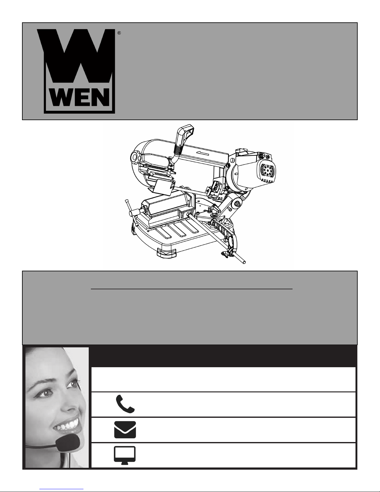
5-INCH PORTABLE
METAL BAND SAW
Model # 3975
bit.ly/wenvideo
IMPORTANT:
Your new tool has been engineered and manufactured to WEN’s highest standards for dependability,
ease of operation, and operator safety. When properly cared for, this product will supply you years
of rugged, trouble-free performance. Pay close attention to the rules for safe operation, warnings,
and cautions. If you use your tool properly and for intended purpose, you will enjoy years of safe,
reliable service.
NEED HELP? CONTACT US!
Have product questions? Need technical support?
Please feel free to contact us at:
800-232-1195
(M-F 8AM-5PM CST)
WENPRODUCTS.COM
Page 2

TABLE OF CONTENTS
Technical Data
General Safety Rules
Specific Safety Rules For Band Saw
Electrical Information
Know Your Band Saw
Assembly
Adjustments
Operation
Maintenance
Troubleshooting
Exploded View & Parts List
Warranty
TECHNICAL DATA
2
3
4
5
6
6
7
9
10
11
12
14
Model Number:
Motor:
Saw Blade:
Cutting Capacity for Square Material:
Cutting Capacity for Circular Material:
Cutting Angle Adjustment:
Blade Speed:
Weight:
2
3975
120 V, 60 Hz, 4.5A, 400W (S6 40%)
56-1/2 x 1/2 in.
5 x 4-7/8 in. (90°)
3-1/8 x 3-15/16 in. (45°)
5 in. diameter (90°)
3-1/8 in. diameter (45°)
0 to 60°
125 to 260 FPM
45 pounds
Page 3
GENERAL SAFETY RULES
Safety is a combination of common sense, staying alert and knowing how your item works. SAVE THESE SAFE-
TY INSTRUCTIONS.
WARNING: To avoid mistakes and serious injury, do not plug in your tool until the following
steps have been read and understood.
1. READ and become familiar with this entire instruction manual. LEARN the tool’s applications, limitations, and
possible hazards.
2. AVOID DANGEROUS CONDITIONS. Do not use power tools in wet or damp areas or expose them to rain.
Keep work areas well lit.
3. DO NOT use power tools in the presence of flammable liquids or gases.
4. ALWAYS keep your work area clean, uncluttered, and well lit. DO NOT work on floor surfaces that are slippery
with sawdust or wax.
5. KEEP BYSTANDERS AT A SAFE DISTANCE from the work area, especially when the tool is operating.
NEVER allow children or pets near the tool.
6. DO NOT FORCE THE TOOL to do a job for which it was not designed.
7. DRESS FOR SAFETY. Do not wear loose clothing, gloves, neckties, or jewelry (rings, watches, etc.) when operating the tool. Inappropriate clothing and items can get caught in moving parts and draw you in. ALWAYS wear
non-slip footwear and tie back long hair.
8. WEAR A FACE MASK OR DUST MASK to fight the dust produced by sawing operations.
WARNING: Dust generated from certain materials can be hazardous to your health. Always
operate the tool in a well-ventilated area and provide for proper dust removal. Use dust collection
systems whenever possible.
9. ALWAYS remove the power cord plug from the electrical outlet when making adjustments, changing parts,
cleaning, or working on the tool.
10. KEEP GUARDS IN PLACE AND IN WORKING ORDER.
11. AVOID ACCIDENTAL START-UPS. Make sure the power switch is in the OFF position before plugging in
the power cord.
12. REMOVE ADJUSTMENT TOOLS. Always make sure all adjustment tools are removed from the saw before
turning it on.
13. NEVER LEAVE A RUNNING TOOL UNATTENDED. Turn the power switch to OFF. Do not leave the
tool until it has come to a complete stop.
14. NEVER STAND ON A TOOL. Serious injury could result if the tool tips or is accidentally hit. DO NOT store
anything above or near the tool.
3
Page 4

GENERAL SAFETY RULES
15. DO NOT OVERREACH. Keep proper footing and balance at all times. Wear oil-resistant rubber-soled footwear. Keep the floor clear of oil, scrap, and other debris.
16. MAINTAIN TOOLS PROPERLY. ALWAYS keep tools clean and in good working order. Follow instructions for lubricating and changing accessories.
17. CHECK FOR DAMAGED PARTS. Check for alignment of moving parts, jamming, breakage, improper
mounting, or any other conditions that may affect the tool’s operation. Any part that is damaged should be properly
repaired or replaced before use.
18. MAKE THE WORKSHOP CHILDPROOF. Use padlocks and master switches and ALWAYS remove starter keys.
19. DO NOT operate the tool if you are under the influence of drugs, alcohol, or medication that may affect your
ability to properly use the tool.
20. USE SAFETY GOGGLES AT ALL TIMES that comply with ANSI Z87.1. Normal safety glasses only have
impact resistant lenses and are not designed for safety. Wear a face or dust mask when working in a dusty environment. Use ear protection such as plugs or muffs during extended periods of operation.
SPECIFIC RULES FOR BAND SAW
1. To avoid injury from unexpected movement, secure the machine to a bench before operating.
2. The machine must be switched off before inserting materials to be cut in the vise or before removing materials
from the vice after cutting operations have been finished.
3. Keep your hands and fingers a safe distance away from the blade at all times.
4. Never attempt to stop the saw blade by hand.
5. Never remove any cutting chips by hand. Use a brush at all times.
6. Never remove any safety guards or safety equipment from the saw.
7. Never leave the machine during operation.
8. Wear eye protection. Do not wear gloves, a necktie, jewelry, or loose clothing during operation.
9. Make sure the saw is on a firm, level surface and properly secured.
10. Use only the recommended accessories.
11. Use extra caution with very large, very small, or awkwardly-shaped workpieces.
12. Keep hands away from blade at all times to prevent accidental injury.
4
Page 5
ELECTRICAL INFORMATION
GROUNDING INSTRUCTIONS
IN THE EVENT OF A MALFUNCTION OR BREAKDOWN, grounding provides the path of least resistance
for an electric current and reduces the risk of electric shock. This tool is equipped with an electric cord that has an
equipment grounding conductor and a grounding plug. The plug MUST be plugged into a matching outlet that is
properly installed and grounded in accordance with ALL local codes and ordinances.
DO NOT MODIFY THE PLUG PROVIDED. If it will not fit the outlet, have the proper outlet installed by a
licensed electrician.
IMPROPER CONNECTION of the equipment grounding conductor can result in electric shock. The conductor with the green insulation (with or without yellow stripes) is the equipment grounding conductor. If repair or
replacement of the electric cord or plug is necessary, DO NOT connect the equipment grounding conductor to a
live terminal.
CHECK with a licensed electrician or service personnel if you do not completely understand the grounding instructions or whether the tool is properly
grounded.
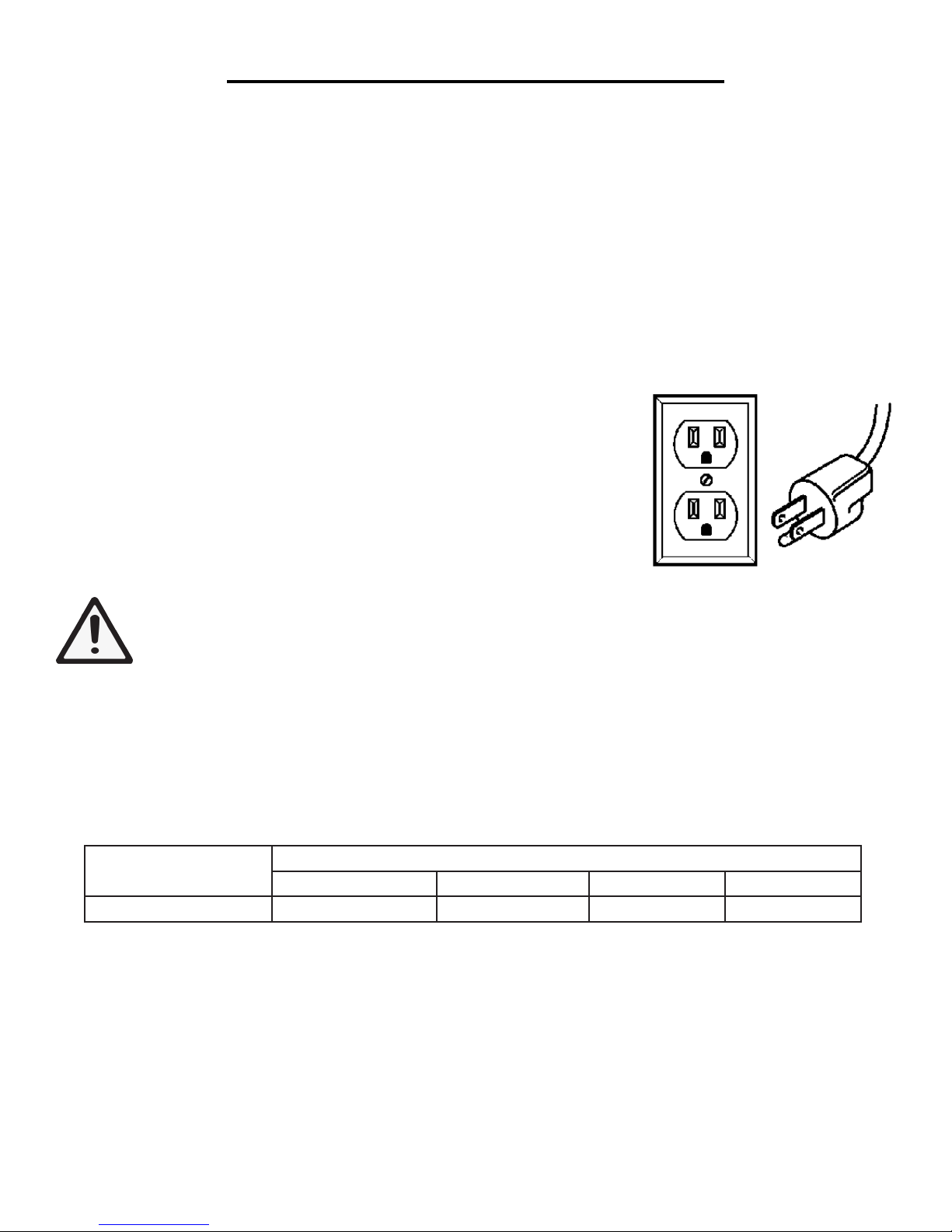
USE ONLY THREE-WIRE EXTENSION CORDS that have three-pronged
plugs and outlets that accept the tool’s plug as shown in Fig. A. Repair or replace a damaged or worn cord immediately.
CAUTION: In all cases, make certain the outlet in question is properly grounded. If you are not sure,
have a licensed electrician check the outlet.
WARNING: This tool is for indoor use only. Do not expose to rain or use in damp locations.
Guidelines for using extension cords
Make sure your extension cord is in good condition. When using an extension cord, be sure to use one heavy
enough to carry the current your product will draw. An undersized cord will cause a drop in line voltage resulting
in loss of power and overheating. The table below shows the correct size to be used according to cord length and
nameplate ampere rating. When in doubt, use a heavier cord. The smaller the gauge number, the heavier the cord.
REQUIRED GAUGE FOR EXTENSION CORDS
AMPERAGE
25 ft. 50 ft. 100 ft. 150 ft.
4.5 A 18 gauge 16 gauge 14 gauge 14 gauge
Make sure your extension cord is properly wired and in good condition. Always replace a damaged extension cord
or have it repaired by a qualified person before using it. Protect your extension cords from sharp objects, excessive
heat and damp/wet areas.
FIGURE A
Use a separate electrical circuit for your tools. This circuit must not be less than a #12 wire and should be protected
with a 15 A time-delayed fuse. Before connecting the motor to the power line, make sure the switch is in the OFF
position and the electric current is rated the same as the current stamped on the motor nameplate. Running at a
lower voltage will damage the motor.
WARNING: This tool must be grounded while in use to protect the operator from electric shock.
5
Page 6
A
C
D
B
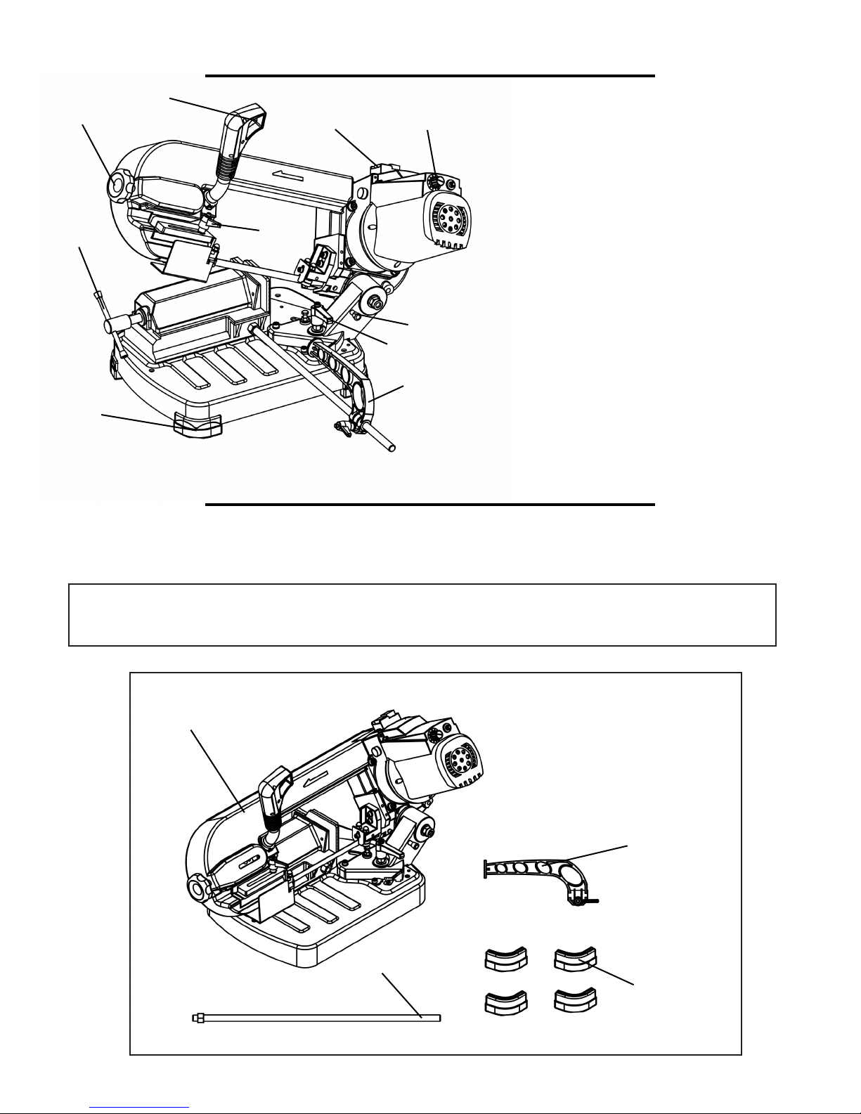
KNOW YOUR BAND SAW
I
J
H
G
F
E
Blade Tension Adjustment Knob
A
Run Switch
B
Vise Adjustment
C
Rubber Feet
D
Work Stop
E
Angle Adjustment Lock
F
Locking Pin
G
Variable Speed Adjustment Knob
H
Power Switch
I
Blade Guide Lock
J
ASSEMBLY
UNPACKING
Carefully unpack the band saw and all its parts, and compare against the list below. Do not discard the carton or
any packaging until the band saw is completely assembled.
WARNING: If any part is missing or damaged, do not
plug in the band saw until the missing or damaged part is replaced.
1
TABLE OF LOOSE PARTS
1. Metal Band Saw
2. Work Stop with Lock Handle
3. Feet (4)
4. Guide Rail with Hex Nut
2
6
4
3
Page 7
ASSEMBLY
ASSEMBLY AND INSTALLATION
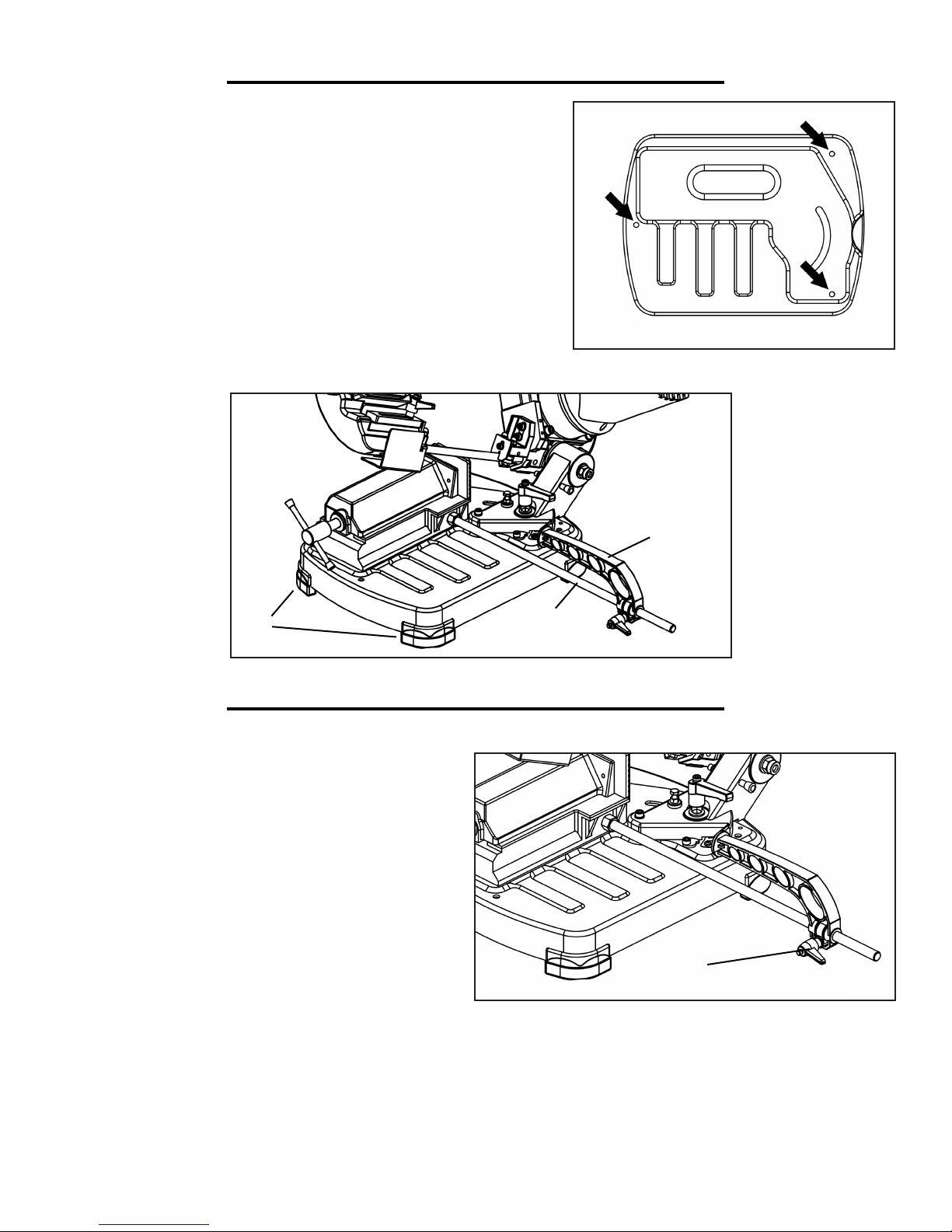
1. Attach the four feet (Fig. B - 1) along each respective corner of
the base.
2. Place the machine onto a work bench and secure it in place by
using the three holes provided in the base (Fig. A).
3. Screw the guide rail to the threaded hole on the vise base.
Tighten the nut to fix it.
4. Attach the work stop (Fig. B - 2) to the guide rail (Fig. B - 3).
Secure it in place by tightening the lock handle.
1
ADJUSTMENTS
POSITIONING THE WORK STOP
Fig. A
2
3
Fig. B
If you have to make a series of cuts with a uniform
length, use the supplied work stop.
1. Loosen the lock handle (Fig. C - 1).
2. Slide the work lock to the desired distance.
3. Tighten the lock handle again.
WARNING: Make sure that the work stop does not
interfere with the downward movement of the blade.
1
Fig. C
7
Page 8
ADJUSTMENTS
CUTTING ANGLE ADJUSTMENT
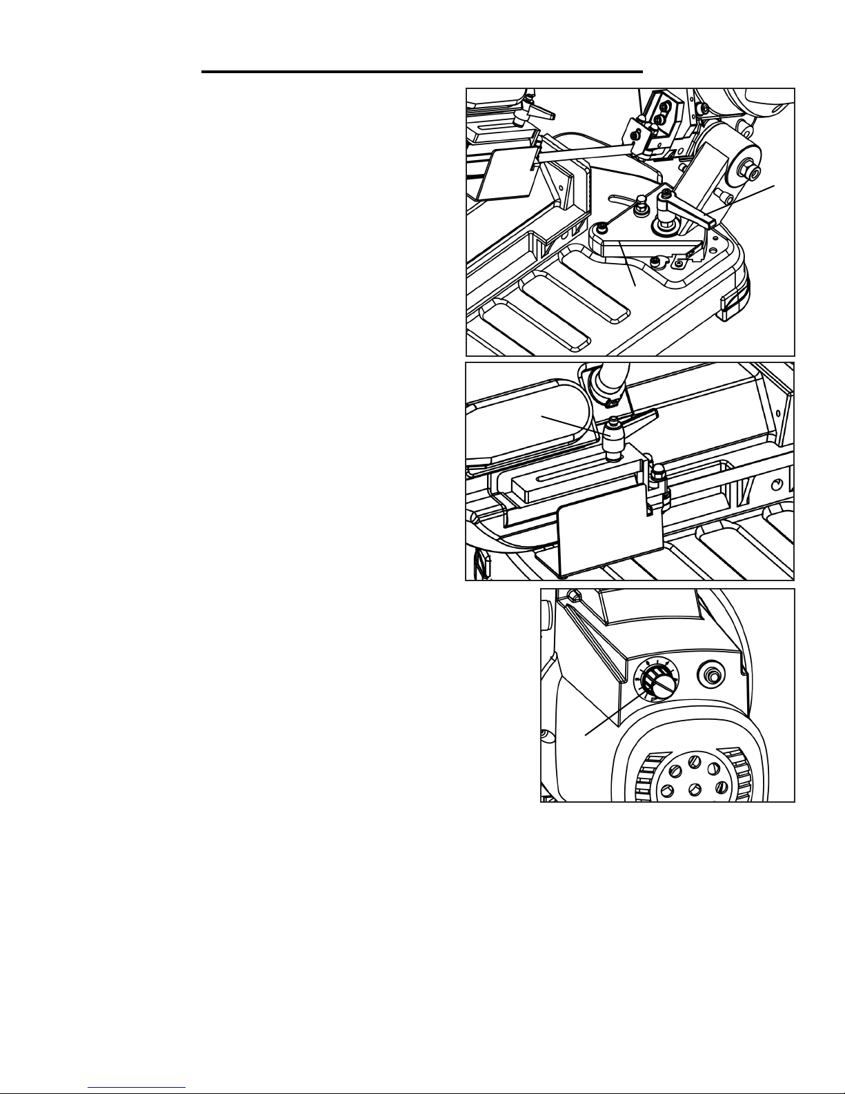
This band saw cuts angles anywhere from 0 to 60 degrees.
To make an adjustment to the cutting angle:
1. Loosen the angle lock handle (Fig. D - 1).
2. Turn the swivel support (Fig. D - 2) until the mark on the
support matches the desired angle on the scale.
3. Lock the angle lock handle.
SLIDING BLADE GUIDE
The sliding blade guide must be adjusted before every cut to
a new workpiece. Without the adjustment, the resulting cut
could be unclean and jagged.
1. Loosen the blade guide lock handle (Fig. E - 1).
2. Slide the blade guide to move it closer to the workpiece.
3. Retighten the blade guide lock handle.
CUTTING SPEED
The cutting speed always depends on the material being cut. To select
the most suitable speed, turn the control knob (Fig. F - 1) to increase
or decrease the speed, with 125 FPM as the lowest setting and 260
FPM the highest.
Fig. E
1
2
Fig. D
1
Fig. F
For common steel, use a speed between 125 and 180 FPM.
For aluminum or alloy, use the maximum speed of 260 FPM.
For pipes, use a speed between 220 and 260 FPM.
88
1
Page 9
OPERATION
1
1
Fig. G Fig. H
Fig. I
1
Fig. J
1
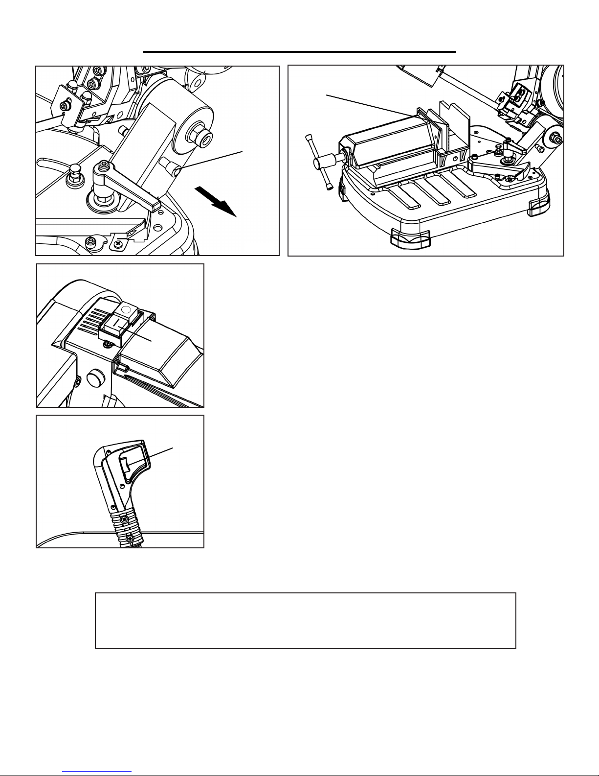
1. Pull out the pin (Fig. G - 1) from the hole in the saw’s body and tilt the
saw to its upper position.
2. Use the vise to secure the workpiece in place (Fig. H - 1). Adjust the cutting speed to the desired rate.
3. Push the green button to turn on the power of the saw (Fig. I - 1). The
blade will not start running until the run button is also activated. Using the
index finger of your right hand, press the run button after turning on the
saw’s power (Fig. J - 1).
4. Once the saw blade has come to full speed, gradually lower the machine’s body downwards until the blade comes into light contact with the
workpiece. Let the saw blade make a small groove along the workpiece to
help ensure a straight cut (particularly with curved or round workpieces).
5. Once initial contact and a groove have been made, apply a small amount
of additional pressure to continue the cut.
NOTE: For optimal performance, cutting should only occur for 40% of the overall run
time. For example, for every 10 minutes the machine is running, only four of those minutes should be under load in order to maximize the performance of the machine
9
Page 10
MAINTENANCE
WARNING: Turn off the machine and disconnect the power supply
before conducting any maintenance work or adjusting any settings.
CHANGING THE SAW BLADE
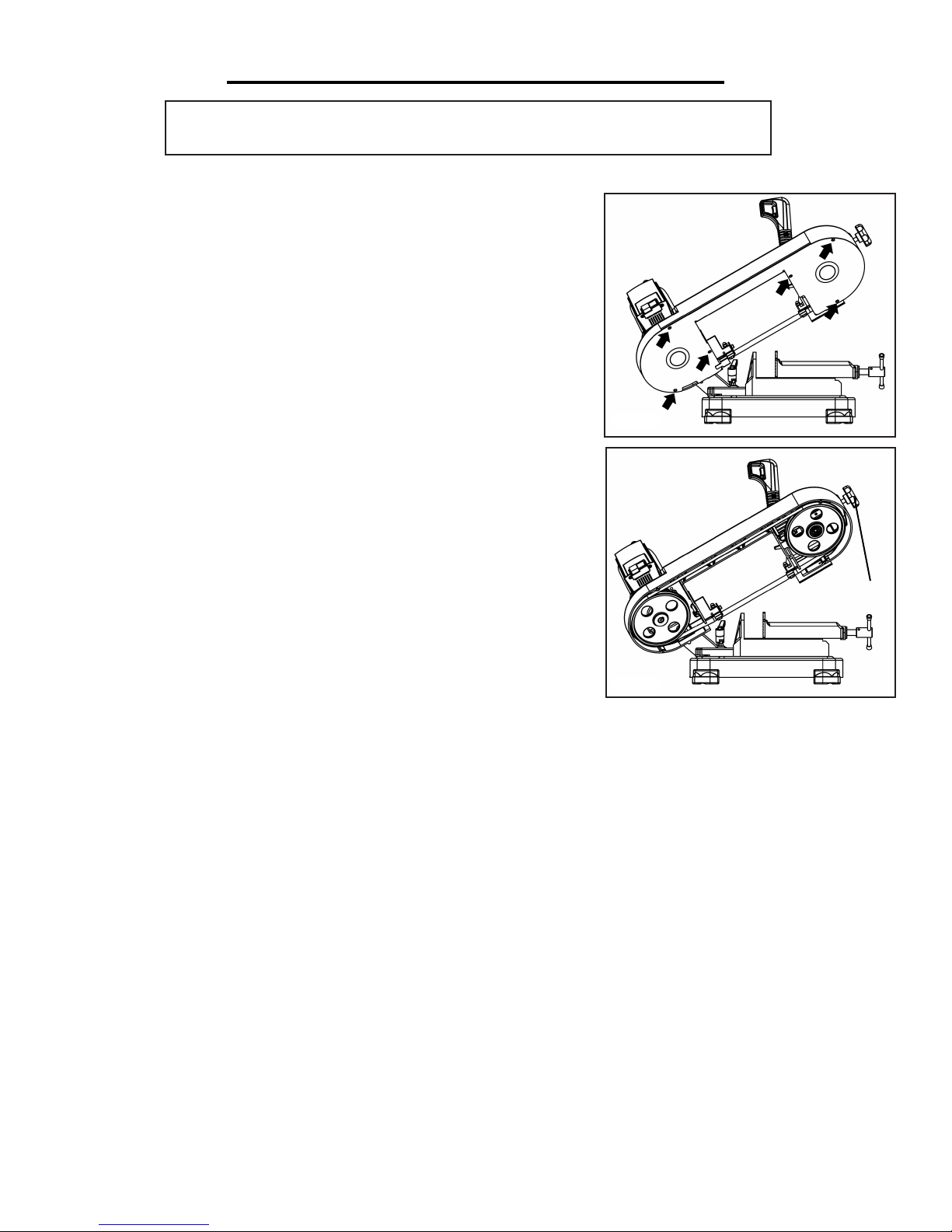
1. Remove the protective casing by unscrewing the six screws shown in
Fig. K.
2. Loosen the blade tension by turning the blade tension adjustment
knob counterclockwise (Fig. L - 1).
3. Carefully remove the blade, first from the guides and then from
around the cast iron pulleys.
4. Insert the new blade, first between the guides and then around the
cast iron pulleys.
5. Turn the blade tension adjustment knob to properly adjust the blade
tension (Fig. L - 1).
6. Replace the protective casing using the six screws in Fig. K.
7. Reposition the blade guides into their correct position for the next cut.
GENERAL MACHINE CARE
• Routinely check the condition of the power supply cords and replace
them if they are broken, worn or if internal wires are showing.
• Use a brush and a shop vacuum to remove chips and other debris from the machine.
• Always keep the machine hand grip clean to prevent accidental slipping during use.
• Remove the processing residues from the cutting area and the blade guides whenever necessary.
Fig. K
Fig. L
1
• If you do not intend to use the sawing machine for a long time, clean it and put it in a dry place if possible. In
these cases, it is advisable to make sure the blade stays slack so that it is not kept under tension during storage for
any reason.
• To ensure effective machine operation, check the condition of the blade daily. Sharpen it as necessary.
10
Page 11

TROUBLESHOOTING
PROBLEM CAUSE SOLUTION
The motor does not work. 1. Defective motor, power cable
or plug.
2. Safety cover is open; interlock
switch does not work.
Overload circuit tripped 1. Motor overload caused by
excessive cutting pressure.
2. Motor breakdown.
Inaccurate cut squaring 1. Excessive cutting pressure.
2. Incorrect blade tooth in relation to the workpiece.
3. Incorrect adjustment of the
sliding blade guide.
4. Incorrect cutting speed in relation to work piece.
5. The workpiece is wrongly positioned in the vise.
6. Poor blade tension.
The blade tends to protrude from
the guide.
1. Excessive blade tension.
2. Incorrect eccentric blade guide
adjustment.
3. The blade slips on the pulleys,
due to the oil or grease required
for cutting operations.
1. Specialized personnel should
check the machine.
2. Close the safety cover.
1. Perform the cut on the piece at
the correct pressure.
2. Specialized personnel should
check the machine.
1. Decrease the cutting pressure.
2. Choose the proper blade for
the given workpiece.
3. Check the blade guide adjustment.
4. Adjust to the correct cutting
speed.
5. Check workpiece positioning
and clamping in the vise.
6. Check the blade tension.
1. Check blade tension.
2. Check eccentric blade guide
adjustment.
3. Never use any type of lubricant or coolant for the cutting
operations; specialized personnel
should check and replace the pulleys if necessary.
11
Page 12
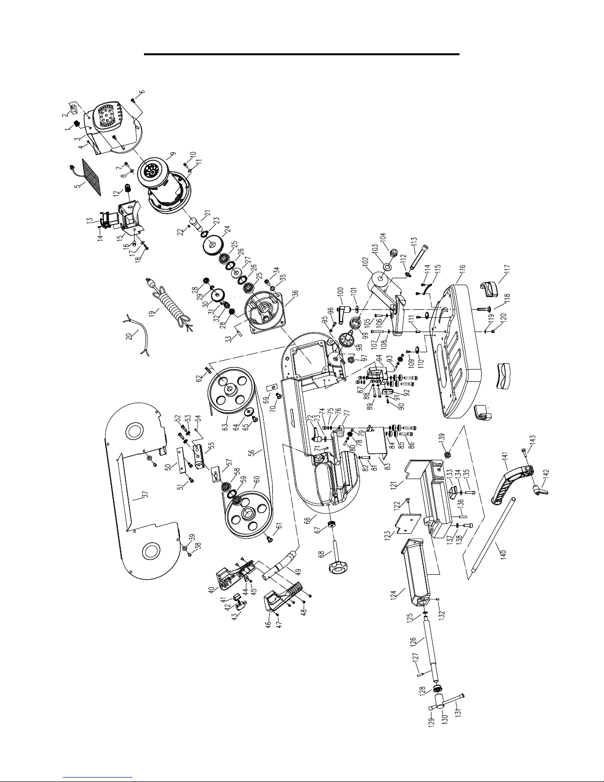
EXPLODED VIEW AND PARTS LIST
12
Page 13
No. Part Description Qty.
49 3975-049 Tube 1
50 3975-050 Guide plate 2
51 3975-051 Socket head screw 4
52 3975-052 Socket head screw 2
53 3975-053 Lock washer 2
54 3975-054 Set screw 1
55 3975-055 Sliding block 1
56 3975-056 Blade 1
57 3975-057 Bevel plate 1
58 3975-058 Ball bearing 2
59 3975-059 Retaining ring 1
60 3975-060 Rear blade wheel 1
61 3975-061 Flat head screw 1
62 3975-062 Key 1
63 3975-063 Front blade wheel 1
64 3975-064 Flat washer 1
65 3975-065 Flat head screw 1
66 3975-066 Frame 1
67 3975-067 Spring washer 8
68 3975-068 Blade tension knob 1
69 3975-069 Cord clamp 2
70 3975-070 Pan head screw 2
71 3975-071 Set screw 1
72 3975-072 Lock handle 1
73 3975-073 Flat washer 1
74 3975-074 Nut 4
75 3975-075 Lock washer 4
76 3975-076 Flat washer 4
77 3975-077 Rear blade guide block 1
78 3975-078 Ball bearing 2
79 3975-079 Flat washer 4
80 3975-080 Pin 1
81 3975-081 Socket head screw 1
82 3975-082 Lock washer 1
83 3975-083 Blade guard 1
84 3975-084 Flat washer 4
85 3975-085 Ball bearing 8
86 3975-086 Shaft 4
87 3975-087 Flat washer 2
88 3975-088 Lock washer 2
89 3975-089 Socket head screw 2
90 3975-090 Socket head screw 1
91 3975-091 Flat washer 1
92 3975-092 Guard plate 1
93 3975-093 Pin 1
94 3975-094 Front blade guide block 1
95 3975-095 Nut 1
96 3975-096 Hex head bolt 1
No. Part Description Qty.
97 3975-097 Nut 1
98 3975-098 Center shaft 1
99 3975-099 Torsion spring 1
100 3975-100 Lock handle 1
101 3975-101 Flat washer 1
102 3975-102 Swivel support 1
103 3975-103 Flat washer 1
104 3975-104 Nut 1
105 3975-105 Hex head bolt 1
106 3975-106 Nut 1
107 3975-107 Socket head screw 1
108 3975-108 Flat washer 1
109 3975-109 Socket head screw 2
110 3975-110 End stop washer 2
111 3975-111 Bushing 1
112 3975-112 Retaining ring 1
113 3975-113 Lock pin 1
114 3975-114 Pan head screw 2
115 3975-115 Angle scale 1
116 3975-116 Base 1
117 3975-117 Foot 4
118 3975-118 Carriage bolt 1
119 3975-119 Flat washer 1
120 3975-120 Nut 1
121 3975-121 Vise base 1
122 3975-122 Flat head screw 2
123 3975-123 Vise jaw 1
124 3975-124 Sliding case 1
125 3975-125 Retaining ring 1
126 3975-126 Screw 1
127 3975-127 Spring pin 1
128 3975-128 Bushing 1
129 3975-129 Handle cap 2
130 3975-130 Socket rod 1
131 3975-131 Handle rod 1
132 3975-132 Set screw 1
133 3975-133 Guide block 1
134 3975-134 Lock washer 1
135 3975-135 Hex head bolt 1
136 3975-136 Spring pin 2
137 3975-137 Lock washer 6
138 3975-138 Socket head screw 6
139 3975-139 Nut 1
140 3975-140 Work stop rod 1
141 3975-141 Work stop 1
142 3975-142 Lock handle 1
143 3975-143 Hex head bolt 1
EXPLODED VIEW AND PARTS LIST
No. Part Description Qty.
1 3975-001 Speed adjusting knob 1
2 3975-002 Circuit breaker 1
3 3975-003 Motor housing 1
4 3975-004 Thread forming screw 2
5 3975-005 Motor driver 1
6 3975-006 Pan head screw 3
7 3975-007 Pan head screw 1
8 3975-008 Serrated washer 1
9 3975-009 Motor assembly 1
10 3975-010 Socket head screw 4
11 3975-011 O ring 4
12 3975-012 Strain relief 1
13 3975-013 Switch 1
14 3975-014 Thread forming screw 2
15 3975-015 Switch box 1
16 3975-016 Indicator light 1
17 3975-017 Flat washer 2
18 3975-018 Thread forming screw 2
19 3975-019 Power cord 1
20 3975-020 Inner line 1
21 3975-021 Front wheel shaft 1
22 3975-022 Key 1
23 3975-023 Retaining ring 1
24 3975-024 50T Gear 1
25 3975-025 Ball bearing 2
26 3975-026 Retaining ring 2
27 3975-027 Oil seal 1
28 3975-028 Ball bearing 2
29 3975-029 Retaining ring 1
30 3975-030 43T Gear 1
31 3975-031 Key 1
32 3975-032 Pinion gear 1
33 3975-033 Spring pin 1
34 3975-034 Socket head screw 4
35 3975-035 Lock washer 4
36 3975-036 Gear box 1
37 3975-037 Frame cover 1
38 3975-038 Pan head screw 6
39 3975-039 Flat washer 6
40 3975-040 Left handle part 1
41 3975-041 Button 1
42 3975-042 Spring 1
43 3975-043 Operating switch 1
44 3975-044 Cord clamp 5
45 3975-045 Pan head screw 5
46 3975-046 Right handle part 1
47 3975-047 Thread forming screw 3
48 3975-048 Flat head screw 4
13
Page 14

LIMITED TWO YEAR WARRANTY
WEN Products is committed to build tools that are dependable for years. Our warranties are consistent with this
commitment and our dedication to quality.
LIMITED WARRANTY OF WEN CONSUMER POWER TOOLS PRODUCTS FOR HOME USE
GREAT LAKES TECHNOLOGIES, LLC (“Seller”) warrants to the original purchaser only, that all WEN consumer power tools will be free from defects in material or workmanship for a period of two (2) years from date of
purchase. Ninety days for all WEN products, if the tool is used for professional use.
SELLER’S SOLE OBLIGATION AND YOUR EXCLUSIVE REMEDY under this Limited Warranty and, to
the extent permitted by law, any warranty or condition implied by law, shall be the repair or replacement of parts,
without charge, which are defective in material or workmanship and which have not been misused, carelessly
handled, or misrepaired by persons other than Seller or Authorized Service Center. To make a claim under this
Limited Warranty, you must make sure to keep a copy of your proof of purchase that clearly defines the Date of
Purchase (month and year) and the Place of Purchase. Place of purchase must be a direct vendor of Great Lakes
Technologies, LLC. Third party vendors such as garage sales, pawn shops, resale shops, or any other secondhand
merchant void the warranty included with this product. Contact [email protected] or 1-800-2321195 to make arrangements for repairs and transportation.
When returning a product for warranty service, the shipping charges must be prepaid by the purchaser. The product must be shipped in its original container (or an equivalent), properly packed to withstand the hazards of shipment. The product must be fully insured with a copy of the warranty card and/or the proof of purchase enclosed.
There must also be a description of the problem in order to help our repairs department diagnose and fix the
issue. Repairs will be made and the product will be returned and shipped back to the purchaser at no charge.
THIS LIMITED WARRANTY DOES NOT APPLY TO ACCESSORY ITEMS THAT WEAR OUT FROM
REGULAR USAGE OVER TIME INCLUDING BELTS, BRUSHES, BLADES, ETC.
ANY IMPLIED WARRANTIES SHALL BE LIMITED IN DURATION TO ONE (1) YEAR FROM DATE
OF PURCHASE. SOME STATES IN THE U.S., SOME CANADIAN PROVINCES DO NOT ALLOW
LIMITATIONS ON HOW LONG AN IMPLIED WARRANTY LASTS, SO THE ABOVE LIMITATION
MAY NOT APPLY TO YOU.
IN NO EVENT SHALL SELLER BE LIABLE FOR ANY INCIDENTAL OR CONSEQUENTIAL DAMAGES (INCLUDING BUT NOT LIMITED TO LIABILITY FOR LOSS OF PROFITS) ARISING FROM
THE SALE OR USE OF THIS PRODUCT. SOME STATES IN THE U.S. AND SOME CANADIAN
PROVINCES DO NOT ALLOW THE EXCLUSION OR LIMITATION OF INCIDENTAL OR CONSEQUENTIAL DAMAGES, SO THE ABOVE LIMITATION OR EXCLUSION MAY NOT APPLY TO
YOU.
THIS LIMITED WARRANTY GIVES YOU SPECIFIC LEGAL RIGHTS, AND YOU MAY ALSO HAVE
OTHER RIGHTS WHICH VARY FROM STATE TO STATE IN THE U.S., PROVINCE TO PROVINCE
IN CANADA AND FROM COUNTRY TO COUNTRY.
THIS LIMITED WARRANTY APPLIES ONLY TO PORTABLE ELECTRIC TOOLS, BENCH POWER TOOLS, OUTDOOR POWER EQUIPMENT AND PNEUMATIC TOOLS SOLD WITHIN THE
UNITED STATES OF AMERICA, CANADA AND THE COMMONWEALTH OF PUERTO RICO. FOR
WARRANTY COVERAGE WITHIN OTHER COUNTRIES, CONTACT THE WEN CUSTOMER SUPPORT LINE.
14
 Loading...