

Page 1
Operating Instructions
WEMPE digital main clock
20097
Page 2

WEMPE digital main clock 20097
Table of contents
2
© Gerhard D. Wempe KG
Division Chronometerwerke
Steinstr. 23
20095 Hamburg - Germany
phone: +49 (0) 40 / 33 44 8 - 899
fax: +49 (0) 40 / 33 44 8 - 676
Kothes!-Dok-ID: 00305
07/2005
V3.0 01/2011
Page 3

WEMPE digital main clock 20097
Table of contents
1 General Information.......................................................................................................... 6
1.1 Information on the operating instructions ...................................................................... 6
1.2 Explanation of the symbols........................................................................................... 6
1.3 Liability and guarantee.................................................................................................. 7
1.4 Copyright protection...................................................................................................... 7
1.5 Transport ...................................................................................................................... 7
1.6 Packaging..................................................................................................................... 8
1.7 Storage......................................................................................................................... 8
1.8 Disposal........................................................................................................................ 8
2 Safety................................................................................................................................. 9
2.1 General information ...................................................................................................... 9
2.2 Intended use................................................................................................................. 9
2.3 Operator’s responsibility ............................................................................................. 10
2.4 Installation and operating staff .................................................................................... 10
3 Technical Data ................................................................................................................ 11
3.1 General Data .............................................................................................................. 11
3.2 Electrical Data ............................................................................................................ 11
4 Design and function ....................................................................................................... 12
4.1 Design ........................................................................................................................ 12
4.1.1 Front view............................................................................................................. 12
4.1.2 System overview .................................................................................................. 13
4.2 Mode of operation....................................................................................................... 14
4.3 Accessories ................................................................................................................ 14
4.3.1 Secondary clocks ................................................................................................. 14
4.3.2 Extension cards.................................................................................................... 14
4.3.3 Accumulator ......................................................................................................... 14
4.3.4 Fuses ................................................................................................................... 15
5 Installation and putting into operation.......................................................................... 16
5.1 Safety ......................................................................................................................... 16
5.2 Requirements on the place of installation ................................................................... 16
5.3 Installation .................................................................................................................. 17
5.3.1 Wall mounting....................................................................................................... 17
5.3.2 Console mounting................................................................................................. 18
5.4 Fitting of cables .......................................................................................................... 18
5.4.1 Fitting of cables at the wall-mounting version ....................................................... 18
V3.0 01/2011
3
Page 4

WEMPE digital main clock 20097
Table of contents
5.4.2 Fitting of cables at the console-mounting version ................................................. 19
5.5 Electrical connection................................................................................................... 19
5.6 Connection of secondary clocks ................................................................................. 20
5.7 Connection of GPS receiver........................................................................................ 20
5.8 Putting into operation.................................................................................................. 21
6 Operation......................................................................................................................... 22
6.1 Make basic settings .................................................................................................... 22
6.1.1 Unlock the keyboard............................................................................................. 22
6.1.2 Select indicated time............................................................................................. 22
6.1.3 Setting of time....................................................................................................... 22
6.1.4 Setting of date ...................................................................................................... 23
6.1.5 Setting of automatic time adjustment.................................................................... 23
6.1.6 Switching on/off and adjusting of display illumination............................................ 23
6.1.7 Lock the keyboard ................................................................................................ 24
6.2 Additional settings....................................................................................................... 24
6.2.1 Remove write protection for additional settings..................................................... 24
6.2.2 Setting of adjustment frequency for analogue secondary clocks........................... 25
6.2.3 Setting of impulse width........................................................................................ 25
6.2.4 Setting of analogue lines....................................................................................... 25
6.2.5 Setting of secondary clocks impulse voltage......................................................... 26
6.2.6 Setting of the internal standard interface............................................................... 27
6.2.7 Programming of relay outputs for error messages ................................................ 27
6.3 Set-up of secondary clocks......................................................................................... 27
6.4 Use of extension cards ............................................................................................... 28
6.4.1 Extension card for digital clocks............................................................................ 28
6.4.2 MOBALine extension cards .................................................................................. 28
6.4.3 Extension card for analogue clocks ......................................................................29
6.4.4 Serial extension card ............................................................................................ 30
6.5 Insertion of GPS receiver............................................................................................ 30
6.5.1 Select GPS receiver ............................................................................................. 30
6.5.2 Setting of baud rate .............................................................................................. 31
6.5.3 Synchronisation of the clock with GPS signal ....................................................... 31
6.5.4 Setting of synchronisation rate.............................................................................. 32
6.6 Programming summary............................................................................................... 33
4
V3.0 01/2011
Page 5

WEMPE digital main clock 20097
Table of contents
7 Trouble shooting............................................................................................................. 34
8 Maintenance.................................................................................................................... 35
9 Annex............................................................................................................................... 37
9.1 Terminal plans ............................................................................................................ 37
9.1.1 Terminal plan for the standard version.................................................................. 37
9.1.2 Terminal board of the extension cards.................................................................. 38
9.2 Block diagram............................................................................................................. 39
9.3 Circuit boards ............................................................................................................. 40
9.3.1 Main board ........................................................................................................... 40
9.3.2 Display and control board..................................................................................... 41
9.3.3 Oscillator board .................................................................................................... 42
9.3.4 Terminal strip board (wall-mounting version) ........................................................ 43
9.3.5 Terminal strip board (console-mounting version) .................................................. 43
9.4 Extension cards .......................................................................................................... 44
9.4.1 SIO Serial interface in-out board (optional) ........................................................... 44
9.4.2 Digital secondary clocks extension card - – out (optional)..................................... 45
9.4.3 Analogue secondary clocks extension card – out (optional).................................. 46
9.4.4 MOBALine secondary clocks extension card – out (optional)................................ 47
9.5 Interface protocols ...................................................................................................... 48
9.5.1 Standard protocol main clock 20097 (terminal 13 / 37) ......................................... 48
9.5.2 Protocol ITRON Interface RS422/485................................................................... 49
9.5.3 Protocol ITRON 2000 Interface RS422/485.......................................................... 50
9.5.4 Protocol NMEA $ZCZDA ...................................................................................... 51
9.5.5 Protocol ECHO..................................................................................................... 52
9.5.6 Protocol IMA51..................................................................................................... 53
9.5.7 Protocol GORGI ................................................................................................... 54
9.5.8 Protocol MITEL..................................................................................................... 55
V3.0 01/2011
5
Page 6

WEMPE digital main clock 20097
General Information
1 General Information
1.1 Information on the operating instructions
These operating instructions describe how to install, operate and maintain the main clock.
In order to use the unit properly it is absolutely necessary to follow the safety instructions and
operating guidelines provided in this document.
The operating instructions are part of the product and need to be kept close to the unit so
that they are at any time within reach of the installation, operation, maintenance and cleaning
staff. If the unit is passed on to a third party, the operating instructions have to be handed
over as well.
1.2 Explanation of the symbols
Important safety and unit-related notices are marked by symbols in these operating
instructions. These instructions need absolutely to be observed to prevent any damage of the
unit.
CAUTION! Risk of injury!
This symbol signalises risks that might cause injury.
You should absolutely follow these operational safety instructions and proceed
with special care.
ATTENTION! Material risk!
This symbol signalises instructions which non-observance might result in
damage, malfunction and/or breakdown of the unit.
NOTICE!
This symbol indicates tips and information, which need to be observed for the efficient
and failure-free operation of the unit.
6
V3.0 01/2011
Page 7

WEMPE digital main clock 20097
General Information
1.3 Liability and guarantee
All information and instructions given in these operating instructions were compiled taking
into account the applicable regulations, the current engineering state-of-the-art as well as our
knowledge and experience of many years.
The translations of the operating instructions were as well produced to the best of our
knowledge. The German version of these operating instructions delivered with the unit is
regarded as authentic text.
The actual scope of delivery may differ from the descriptions and illustrations provided in this
manual in case of modifications made according to buyer’s specifications or if additional
technical features have been ordered.
Should you have any questions, please contact the manufacturer.
NOTICE!
Please read these operating instructions thoroughly before starting to operate and to
use the unit, especially before putting it into operation! The manufacturer does not
assume any liability for any damage or malfunction caused by non-observance of the
operating instructions.
1.4 Copyright protection
The operating instructions have to be kept in confidence. They are only meant for the staff
responsible for the unit or charged with its operation or maintenance. It is not permitted to
pass on the operating instructions to a third party, unless prior written approval. If necessary,
please contact the manufacturer.
NOTICE!
The contents, texts, drawings, pictures and other illustrations are protected by
copyright and other industrial property rights. Any kind of misuse is regarded as an
offence and liable to prosecution.
Any kind of copies, also in extracts, as well as the utilisation and/or publication of the content
is not allowed, unless prior written approval of the manufacturer. Violators will be liable to pay
damages. The manufacturer reserves the right to make further claims.
1.5 Transport
ATTENTION! Material risk!
Move the unit always with outmost care.
Check the consignment immediately upon receipt for completeness and damage during
transport.
Should there be an obvious transport damage, do not accept the consignment for delivery or
only under reservation. Note down the extend of the damage on the forwarder’s transport
documents / the delivery note and make a complaint.
A complaint shall be made immediately if hidden defects are ascertained because
compensation can only be claimed within the valid complaint period.
V3.0 01/2011
7
Page 8

WEMPE digital main clock 20097
General Information
1.6 Packaging
If no arrangements have been made for taking back the packaging, please separate the
materials by kind and size for further use or waste recycling.
NOTICE! Environmental caretaking!
Packaging materials are made of valuable resources and can often be used again or
processed and recycled in a sensible way.
1.7 Storage
Always store the unit in its packaging until installation.
The unit shall be stored as follows:
– Keep it at a dry place. Relative humidity: 60 % at maximum.
– Do not store it outside or in an aggressive atmosphere.
– Protect it from direct sunlight. Storage temperature: 15 to 25 °C (59 to 77 °F)
– Store it dust-free and avoid mechanical shocks or damages.
– Do not store it beneath other items and do not charge it with other items.
– In case of a storage period of more that approx. 3 months, check necessary
mothballing measures.
1.8 Disposal
If no arrangements have been made with the manufacturer for taking back the unit, dismount
it in accordance with applicable safety and environmental protection regulations for disposal
and recycling of suitable components.
• Metal residues to be sent to be scrapped.
• Plastic components to be recycled.
• Separate the remaining components by material and dispose of them.
ATTENTION! Environmental risk!
Electronic components and batteries are hazardous waste and have to be treated
by approved hazardous waste disposal sites!
8
V3.0 01/2011
Page 9

WEMPE digital main clock 20097
Safety
2 Safety
All important safety aspects are summarized in this section for a safe and failure-free
operation of the unit.
The individual chapters contain in addition specific instructions marked by symbols.
Furthermore, the inscriptions on the unit need to be observed and should always be kept in
legible condition.
1.1 General information
The unit is designed and manufactured according to the state-of-the-art of good engineering
practice and is safe to operate.
However, the unit might represent a risk if it is not appropriately operated or not operated in
accordance with the regulations by persons lacking corresponding training.
Every person charged with the operation of the unit, shall read and understand the operating
instructions prior to operate the unit. We recommend the operator to request its staff to
confirm in writing that they are aware of the operating instructions.
Any kind of modification, alteration or extension of the unit is prohibited.
The indicated range of settings and operating conditions shall be kept.
1.2 Intended use
The safe operation is only guaranteed provided that the unit is used for its intended use and
according to the instructions.
The digital main clock 20097 is intended for the central control of secondary clocks and/or
secondary clock systems with impulses of 12V or 24V for the synchronised indication of time
and date.
ATTENTION! Material risk!
Any other use of the unit in excess of the intended use as described above
and/or differing form the intended use is prohibited and is regarded as improper
use.
Any kind of claim against the manufacturer and/or its agent due to loss or
damage resulting from improper use is excluded.
The operator is solely liable for any loss or damage due to improper use.
The proper and intended use also refers to the correct compliance with the instructions for
installation, operation and cleaning.
V3.0 01/2011
9
Page 10

WEMPE digital main clock 20097
Safety
1.3 Operator’s responsibility
These operating instructions shall be kept close to the unit so that they are at any time within
reach of the installation, operation and maintenance staff.
The operator and his authorized staff are responsible for the failure-free operation of the unit
as well as for the unequivocal appointment of responsibilities for installation, operation and
maintenance of the unit.
The unit shall only be used if its condition is faultless and safe to operate.
The instructions given in this operating manual are to be followed in their entity and without
exception.
1.4 Installation and operating staff
The unit shall only be installed and operated by authorized and trained staff or other qualified
personnel.
Any staff member that has been previously informed about the tasks assigned to him or her
as well as the possible risks in case of improper conduct and who has been trained
appropriately if necessary and who as been instructed about the necessary safety
dispositions and measures is regarded as trained staff.
Qualified staff is defined as any person who is able to evaluate the tasks assigned to him/her
and to realize any possible risk due to his/her professional training, knowledge and
experience as well as knowledge of the applicable regulations.
The operating company and the operating staff are equally responsible to make sure that no
non-authorized person operates or handles the unit. The operating staff is obliged to inform
the operating company without delay about any change of the unit, which could affect its
functioning or safety.
10
V3.0 01/2011
Page 11

WEMPE digital main clock 20097
3 Technical Data
1.1 General Data
case material: plastic (RAL 7035)
protection type: IP54
mounting: wall-mounting or console-mounting
version
dimensions wall-mounting case width: 257 mm
(incl. terminal box): height: 217 mm
depth: 125 mm
console-mounting case width: 257 mm
(incl. terminals): height: 156 mm
depth: 142 mm
weight wall-mounting case: 2,7 kg
Technical Data
console-mounting case: 1,7 kg
display alphanumeric LC-display with 20 digits
switch-on/switch-off and dimmable display illumination
control processor-controlled C-MOS technology
oscillator quartz-controlled with temperature compensation
accuracy: 0,05 s/24 h
interfaces serial RS485 interface with standard protocol
GPS input RS422 & PPS input for synchronisation
2 relay outputs for alarm annunciators
further optional interfaces
secondary clocks up to 100 fwd. and 50 fwd. and bwd. adjustable clocks
analogue: all common clocks for 12V or 24V impulses
digital: with suitable extension card (optional)
time adjustment intervals ± 1 min or in preset steps between 1 and 99 min
1.2 Electrical Data
power supply 24 V DC, 300 mA
power reserve main clock 4 h (12 V accumulator with 0,7 Ah)
connections 48-pole terminal strip
cable entry by VG screw connections
impulses to secondary
clocks
relay outputs max. 125 V / 0,5 A
V3.0 01/2011
11
12 V or 24 V
for MOBALine option: 15 V (50 Hz)
Page 12
WEMPE digital main clock 20097
Design and function
4 Design and function
1.1 Design
1.1.1 Front view
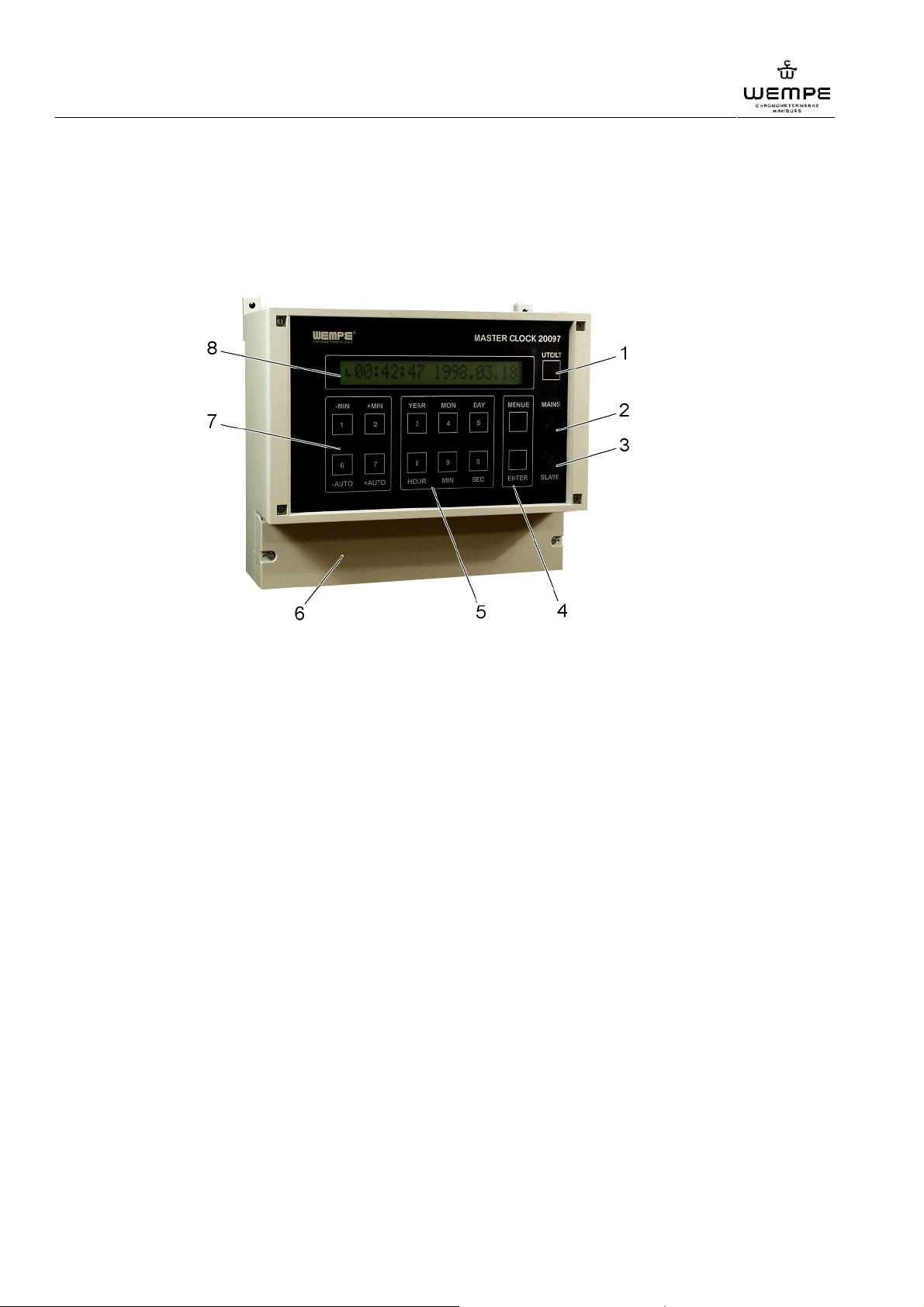
Ill. 1: Front view (wall-mounting case)
1 shift-key coordinated universal time (UTC) / local time (LT)
( see also "operation", "select time display")
2 main fuse ("MAINS") medium blow 1,0 A
for fuse protection of the internal circuit ( see also "accessories")
3 secondary clocks fuse ("SLAVE") medium blow 2,5 A
for fuse protection of the power supply circuit ( see also "accessories")
4 control and confirmation key
to select and confirm menu and setting functions
5 input field for the basic setting
for the basic settings and to adjust the menu and setting functions
6 terminal box
incl. terminal strip and accumulator ( see also "maintenance")
7 input field for setting of time
for gradual setting of time and to adjust the menu and setting functions
8 dimmable display
( see also "operation", "switch on/off, adjust display illumination")
12
V3.0 01/2011
Page 13
24V D
1.1.2 System overview
1
WEMPE digital main clock 20097
Design and function
2
3
C
24V DC 230V AC
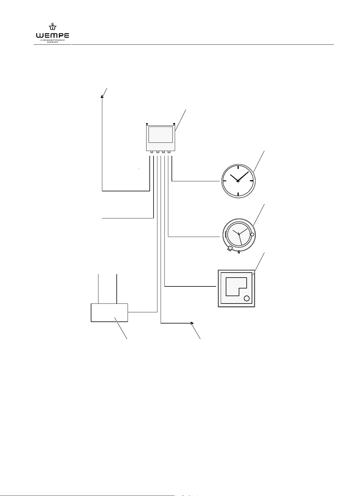
Ill. 2: System overview
1 GPS or DCF77 connection
4
12
39
6
5
30
12
00
67
2 digital main clock 20097
3 analogue secondary clocks
4 analogue secondary clocks with seconds display
5 digital secondary clocks (optional)
6 external interface
7 external mains adaptor
V3.0 01/2011
13
Page 14

WEMPE digital main clock 20097
Design and function
1.2 Mode of operation
The main clock 20097 controls and operates analogue (optionally as well digital) secondary
clocks by impulses.
A highly precise quartz-controlled oscillator with an average accuracy of ± 0,05 s/24 h
provides the control pulse for the main clock’s UTC. Or if a GPS receiver is connected its
receiver signal provides the control pulse.
When travelling through different time zones, the LT of the main clock has to be adjusted
manually. Analogue secondary clocks are readjusted automatically after the preset interval.
MOBALine-secondary clocks set themselves automatically after 3-4 s. Digital secondary
clocks adopt the modified LT without time delay.
1.3 Accessories
1.1.1 Secondary clocks
We offer a wide range of secondary clocks. Please contact us for a presentation of our
assortment.
1.1.2 Extension cards
Depending on the customer’s specification, the following extension cards are included in the
delivery or optionally available ( see also "Appendix", section "Extension cards"):
• digital clocks extension card
for the operation of digital secondary clocks
• MOBALine extension card
for self-adjusting secondary clocks
• analogue clocks extension card
for the operation of more than 100 forwards or 50 forwards and backwards
running analogue secondary clocks.
• serial extension card
for the operation of two different protocols with a differing data frame
1.1.3 Accumulator
The unit is fitted with an accumulator as power reserve. Only when the accumulator is
completely discharged, the clock switches itself off automatically.
The following accumulator types are used:
• pbq VRLA accumulator 0.8-12
• Le Long WP0.8-12
• or comparable accumulators with identical performance
NOTICE!
Do only use these accumulator types or comparable accumulators when replacing the
accumulator (see also section "Maintenance").
14
V3.0 01/2011
Page 15

WEMPE digital main clock 20097
Design and function
1.1.4 Fuses
Main fuse ("MAINS") medium blow 1,0 A (DIN 41571; 5x20 mm)
The main fuse protects the internal processor circuit, the oscillator and the accumulator
charge circuit.
In case of a failure of the main fuse, the main clock switches over to the internal accumulator
power supply. The display shows the error symbol "E" ( see also "troubleshooting").
Secondary clocks fuse ("SLAVE") medium blow 2,5 A (DIN 41571; 5x20 mm)
The secondary clocks fuse protects the external power supply circuit of the digital secondary
clocks, the data outputs of all standard and extension cards as well as the internal interface
and the power supply circuit of the display illumination.
In case of a failure of the secondary clocks fuse, the power supply of the secondary clocks is
interrupted and they stop running. The display shows the error symbol "E" ( see also
"troubleshooting").
V3.0 01/2011
15
Page 16

WEMPE digital main clock 20097
Installation and putting into operation
5 Installation and putting into operation
1.1 Safety
CAUTION! Electric energy hazard!
The improper installation of the electrically operated main clock may cause
injuries or damages of the unit. For that reason:
– The unit shall be installed in accordance with the safety regulations by trained staff
qualified in electrical engineering only!
– Before starting with the installation, make sure it is volt-free and prevent any
1.2 Requirements on the place of installation
possibility of reconnection!
The clock’s construction is shake and shockproof. Nevertheless, the following conditions
apply when choosing an installation place:
– no direct sunlight
– ambient temperature: 0-40 °C
– max. relative humidity 0-90 % without condensation
Special care has to be taken for the wall-mounting version:
ATTENTION! Material risk!
The mounting place has to be chosen so that the main clock does not obstruct
any motion areas of objects (e.g. doors) or people.
16
V3.0 01/2011
Page 17
1.3 Installation
1.1.1 Wall mounting
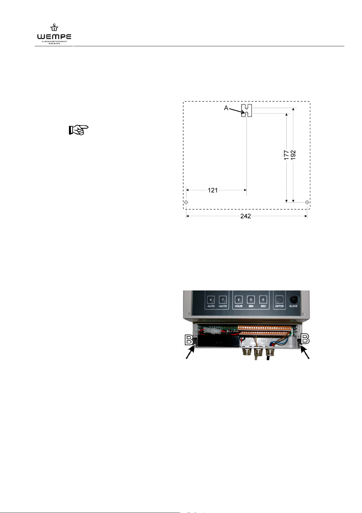
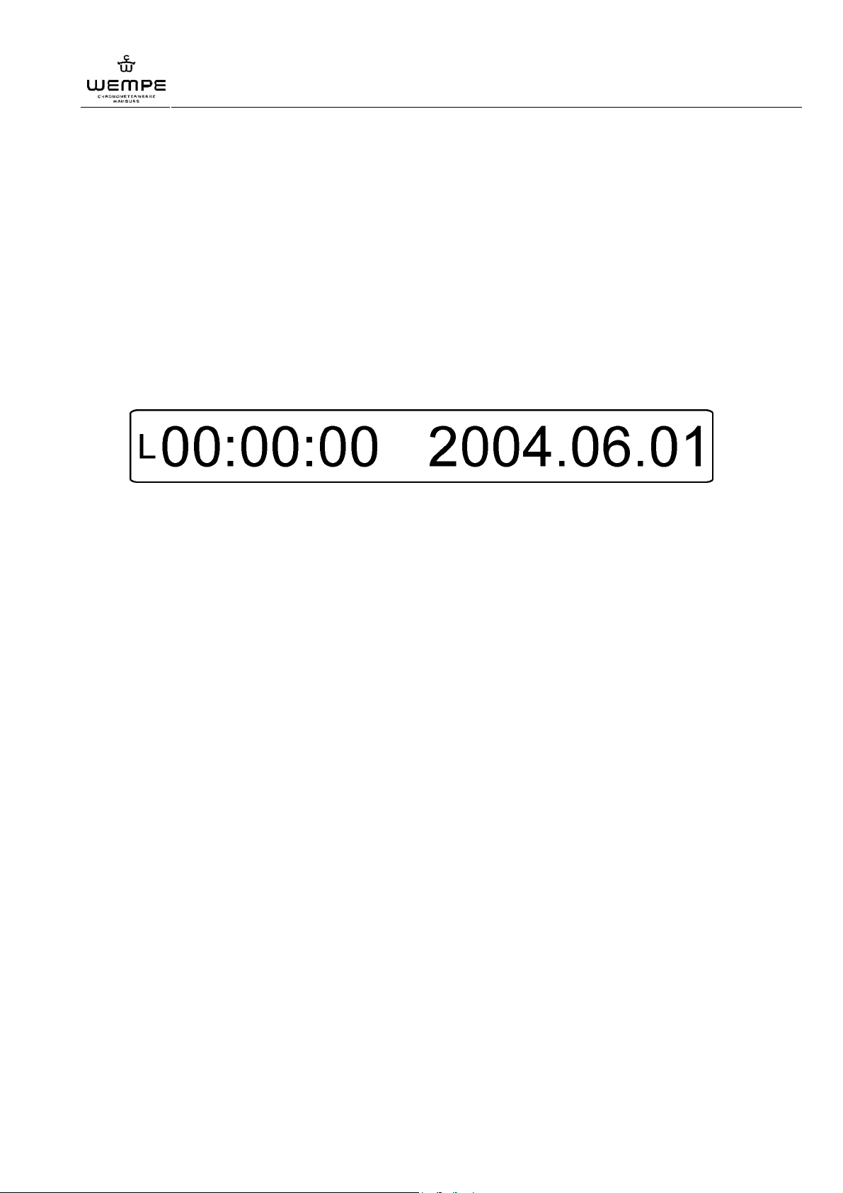
1. Prepare the wall holder according to
the drilling template.
NOTICE!
Size the drill hole diameter for M4
thread screws (e.g. for mounting on
a metal wall) or for 4x30 wood
screws (for mounting on a wooden
wall).
Use the lower drill hole at position
(A) to place the wall hook on the
top, in the middle.
WEMPE digital main clock 20097
Installation and putting into operation
Ill. 3: Drilling template for the wall
holder
2. Fix the wall hook on the wall so that the main clock can be safely fitted at the upper
middle position ( position A).
3. Unscrew both crews of the main clock’s terminal box cover and remove the cover.
4. Fit the main clock on the wall hook. Pay attention that the main clock stays reliably on
the wall, if necessary readjust the wall holder.
5. Insert a thread screw M4 (or a wood
screw 4x30 in case of mounting on a
wooden wall) in the left and right
fitting hole (B).
Ill. 4: Fitting holes (B)
6. Make sure that the main clock hangs safely and reliably on the wall, then place the
cover back on the terminal box and tighten both screws carefully (tightening torque
max. 5 Nm!) until the connection box is securely closed. Ensure protection class IP 54!
V3.0 01/2011
17
Page 18
WEMPE digital main clock 20097
Installation and putting into operation
1.1.2 Console mounting
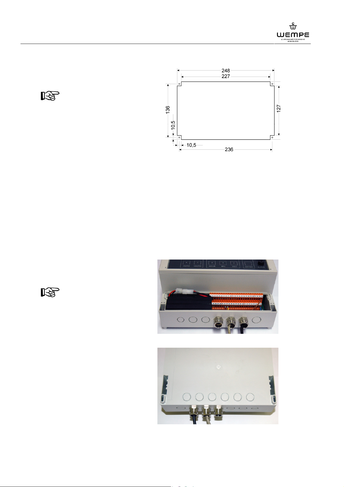
1. Prepare the switchboard cut-out
according to the illustration.
NOTICE!
Size the drill hole diameter for M4
thread screws.
2. Insert the main clock from above into the switchboard cut-out.
3. Place M4 thread screws from above into the edges of the main clock and fit them
tightly from the backside of the switchboard with washers and nuts.
Ill. 5: Switchboard cut-out
4. Make sure that the main clock holds reliably and safely on the console.
1.4 Fitting of cables
1.1.1 Fitting of cables at the wall-mounting version
1. Unscrew both screws of the main clock’s terminal box cover and remove the cover.
2. Pierce a pre-cut hole for the cable
entry from the bottom to the inside.
Clean the cable hole.
NOTICE!
It is also possible to place the cable
entry on the back of the main clock.
For this effect:
a) Dismount the main clock in
reverse order from the wall.
( 1.1.1 Wall mounting).
b) Pierce a pre-cut hole from the
back to the inside.
Ill. 6a: pre-cut holes on the bottom
c) Clean the cable hole. Insert the
cable according to the following
description.
d) Mount the main clock back on the
wall.
18
Ill. 6b: pre-cut holes on the back
V3.0 01/2011
Page 19

WEMPE digital main clock 20097
Installation and putting into operation
3. Set the matching PG screw connection for the cable to be fitted into the cable hole.
4. Insert the cable through the PG screw connection into the terminal box.
Make sure that the hole is tightly closed. Ensure protection class IP 54!
5. Fix the cable leads to the corresponding terminals of the terminal strip.
6. Put the cover back on the terminal box and tighten both screws carefully (tightening
torque max. 5 Nm!) until the connection box is securely closed. Ensure protection class
IP 54!
1.1.2 Fitting of cables at the console-mounting version
Electric cables are connected to the terminal strip on the back of the main clock. The cable
has to be laid and fixed in the console in a way that it does not rip off when the console is
opened or that the cable, the terminal strip and the fasteners are not otherwise damaged.
Make sure that the cables, the terminal strip and the fasteners do not rip off, are not jammed,
squeezed or otherwise damaged when the console is closed. Ensure protection class IP 54!
1.5 Electrical connection
1. Fit the cable for the power supply ( 1.4 Fitting of cables).
2. Connect the +24V lead of the power supply cable and the 0V lead to terminal 48. Make
sure that the polarity of the leads is correct and they are connected firmly to the
terminal.
3. Fix accumulator 12V/0,7Ah
• Wall-mounting version:
Place the accumulator on the bottom, left-hand side of the terminal box.
• Console-mounting version:
Place the accumulator in the holder on the case back.
4. Connect the accumulator via the plug connection or connect the lead of the pluselectrode (+) to terminal 1 and the lead of the minus-electrode (-) to terminal 2. Make
sure that the polarity of the leads is correct and they are connected firmly to the
terminal
5. Close the electrical connections ( 1.4 Fitting of cables). Ensure protection class IP54.
V3.0 01/2011
19
Page 20

WEMPE digital main clock 20097
Installation and putting into operation
1.6 Connection of secondary clocks
The standard version of the main clock can control up to 100 forward and up to 50 forward
and backward adjustable secondary clocks. All common secondary clock systems for 12V or
24V impulses can be connected.
The MOBALine secondary clocks are powered with 15V/50Hz AC-voltage by the main clock
via a 2-wire conductor. At the same time the current time is transmitted by means of
amplitudes/frequency modulation. Time adjustments effected on the main clock, are
automatically recognized by the secondary clocks and reproduced.
If several secondary clocks are to be connected, they have to be connected in parallel first
via a power distribution system. The power distribution system is then connected to the main
clock via a supply line.
1. Fit the cables for the secondary clocks supply line. ( 1.4 Fitting of cables)
2. Fix the leads of the secondary clock’s supply line to the corresponding terminals (either
to terminals 7 and 9 or terminals 32 and 33, for MOBALine extension additionally
terminals 20 and 44) according to the terminal plan ( annex). Make sure that the
leads are connected firmly to the terminals.
3. Close the electrical connections ( 1.4 Fitting of cables). Ensure protection class IP54.
1.7 Connection of GPS receiver
The main clock can adopt the time signal of a GPS receiver.
All types of GPS receivers supporting the "NMEA 0183 Version 2.0" standard are included in
the basic configuration (for example: MAGNAFOX and LEICA).
Receiver types from other manufacturers can be installed. The description of the output
protocol of the corresponding GPS receiver is needed for this purpose.
1. Fit the cables for the GPS receiver supply line ( 1.4 Fitting of cables)
2. Fix the leads of the GPS receiver supply line according to the terminal plan to the
terminals 15 and 16 as well as to the terminals 40 and 41. Make sure that the leads are
connected firmly to the terminals.
3. Close the electrical connections ( 1.4 Fitting of cables). Ensure protection class IP54.
20
V3.0 01/2011
Page 21
WEMPE digital main clock 20097
Installation and putting into operation
1.8 Putting into operation
When delivered, the main clock is equipped, pre-set and pre-installed according to the basic
configuration that was ordered. Once the connections are fitted, the main clock is ready for
operation.
Future modifications of the main clock and the secondary clock system are carried out by
means of the menu functions.
Putting into operation the main clock:
1. Make sure that the polarity of all cable connections is correct, that the connection is
tight with a reliable contact.
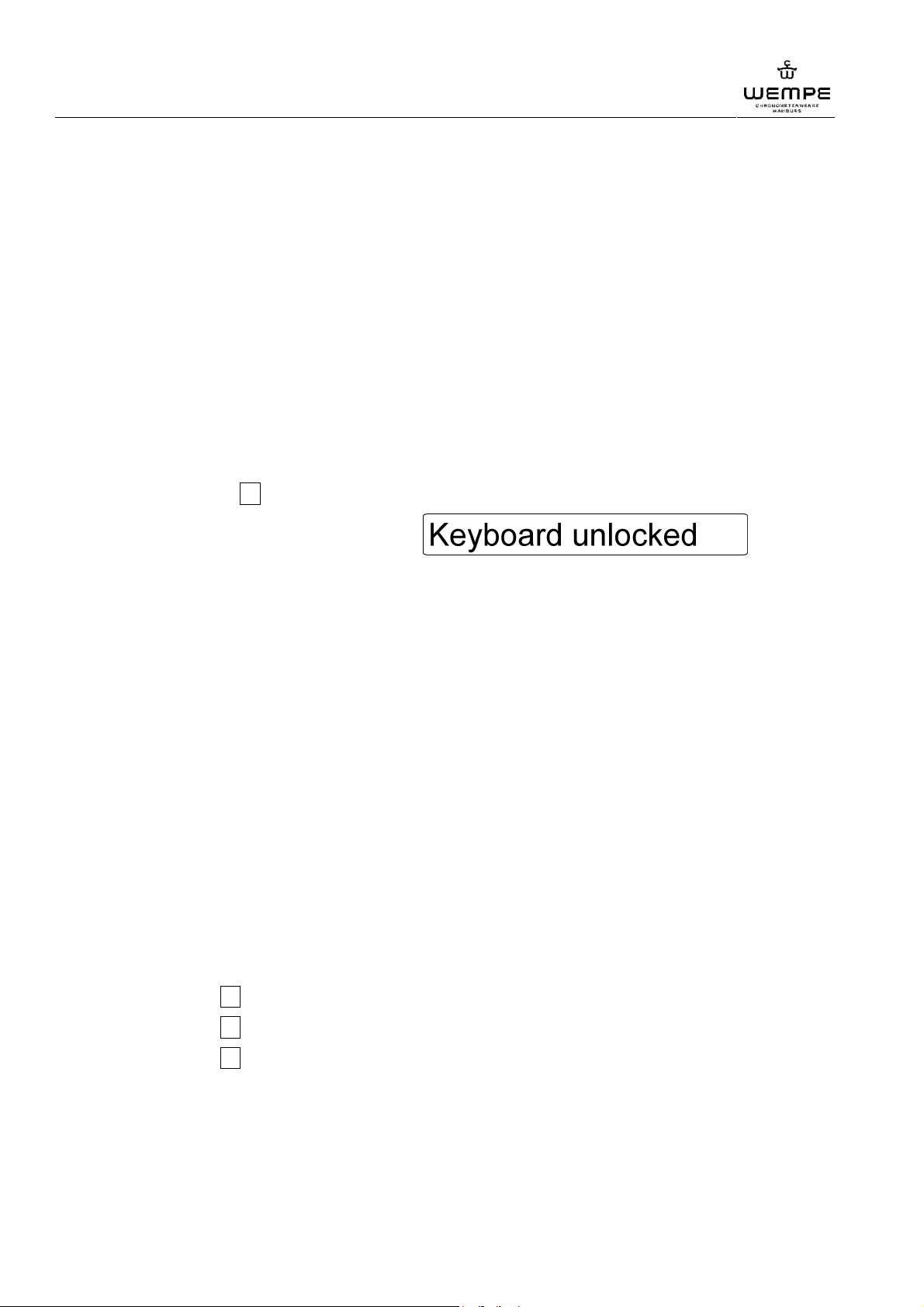
2. Switch on the power supply. The following line appears on the display:
Ill. 7: Start display
L Indication of the selected time.
After switch-on, the main clock is set to Local Time.
00:00:00 Indication of time.
After switch-on, the main clocks starts to run at 0 o’clock.
2004.06.01 Indication of date.
After switch-on, the creation date of the software is indicated.
V3.0 01/2011
21
Page 22
WEMPE digital main clock 20097
Operation
6 Operation
1.1 Make basic settings
After having switched on the power supply, the main clock starts running immediately and
the start display appears ( "Putting into operation").
In order to use the further functions of the main clock, it is necessary to enter the current data
(coordinated universal time/ local time / date) first.
1.1.1 Unlock the keyboard
The keyboard is locked to prevent maloperation.
1. Press the MENUE key for at least 4 seconds until the version number appears on the
display.
2. Press the key 2 once.
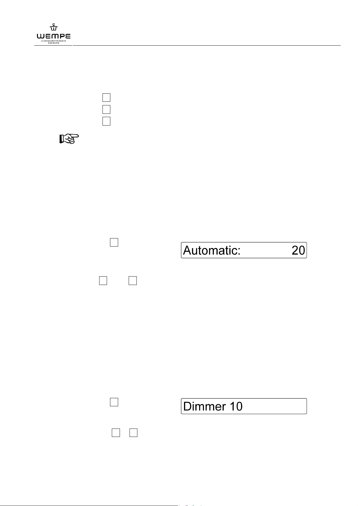
3. Press the ENTER key until the
message on the right appears :
The keyboard is now unlocked.
4. Press the MENUE key to return to the time display.
1.1.2 Select indicated time
The first symbol on the display shows which time is selected for indication.
"L" = indication of the local time
"U" = indication of the coordinated universal time
With the key UTC/LT on the right, next to the display you can switch from LT (Local Time) to
UTC (Coordinated Universal Time) and vice versa.
1.1.3 Setting of time
In the following the setting of the main clock time is described.
1. Select the indicated time ( 1.1.2)
2. Press at the same time the ENTER key and one of the following number keys:
• ENTER + 8 to set the hour
• ENTER + 9 to set the minute
• ENTER + 0 to set the second
Setting of the secondary clocks see 1.3.
22
V3.0 01/2011
Page 23
WEMPE digital main clock 20097
Operation
1.1.4 Setting of date
1. Select the indicated time ( 1.1.2)
2. Press at the same time the ENTER key and one of the following number keys:
• ENTER + 3 to set the year
• ENTER + 4 to set the month
• ENTER + 5 to set the day
NOTICE!
The data transmitted by the interface RS422/485 is also based on this settings. UTC as
well as LT and date are transmitted and must thus be set correctly.
1.1.5 Setting of automatic time adjustment
In order to adjust the local time to the current position the main clock is equipped with an
automatic time adjustment function that adjusts the time forwards or backwards in preset
intervals of up to 99 minutes. This value is pre-set to 20 minutes upon delivery of the unit.
1. Press the MENUE key for at least 4 seconds until the version number appears on the
display.
2. Press the key 2 several times until
the Automatic setting menu ( Ill.)
appears on the display:
3. Press the ENTER key to confirm the selection. The minutes display is flashing.
4. Press key 1 or key 2 to modify the set value in intervals of 1 minute.
5. Press the ENTER key to confirm the new entry.
6. Press the MENUE key to return to the time display.
1.1.6 Switching on/off and adjusting of display illumination
1. Press the ENTER key and the UTC/LT key at the same time to switch the illumination
on or off.
The brightness of the illumination is pre-set by the manufacturer to the highest value (10).
Change the brightness of the illumination:
1. Press the MENUE key for at least 4 seconds until the version number appears on the
display.
2. Press the key 1 until the dimmer
menu ( Ill.) appears on the display:
3. Press the ENTER key to confirm the selection. The pre-set value is flashing.
4. Press the key 1 or 2 to modify the value continuously.
5. Press the ENTER key to confirm the newly set value.
6. Press the MENUE key to return to the time display.
V3.0 01/2011
23
Page 24
WEMPE digital main clock 20097
Operation
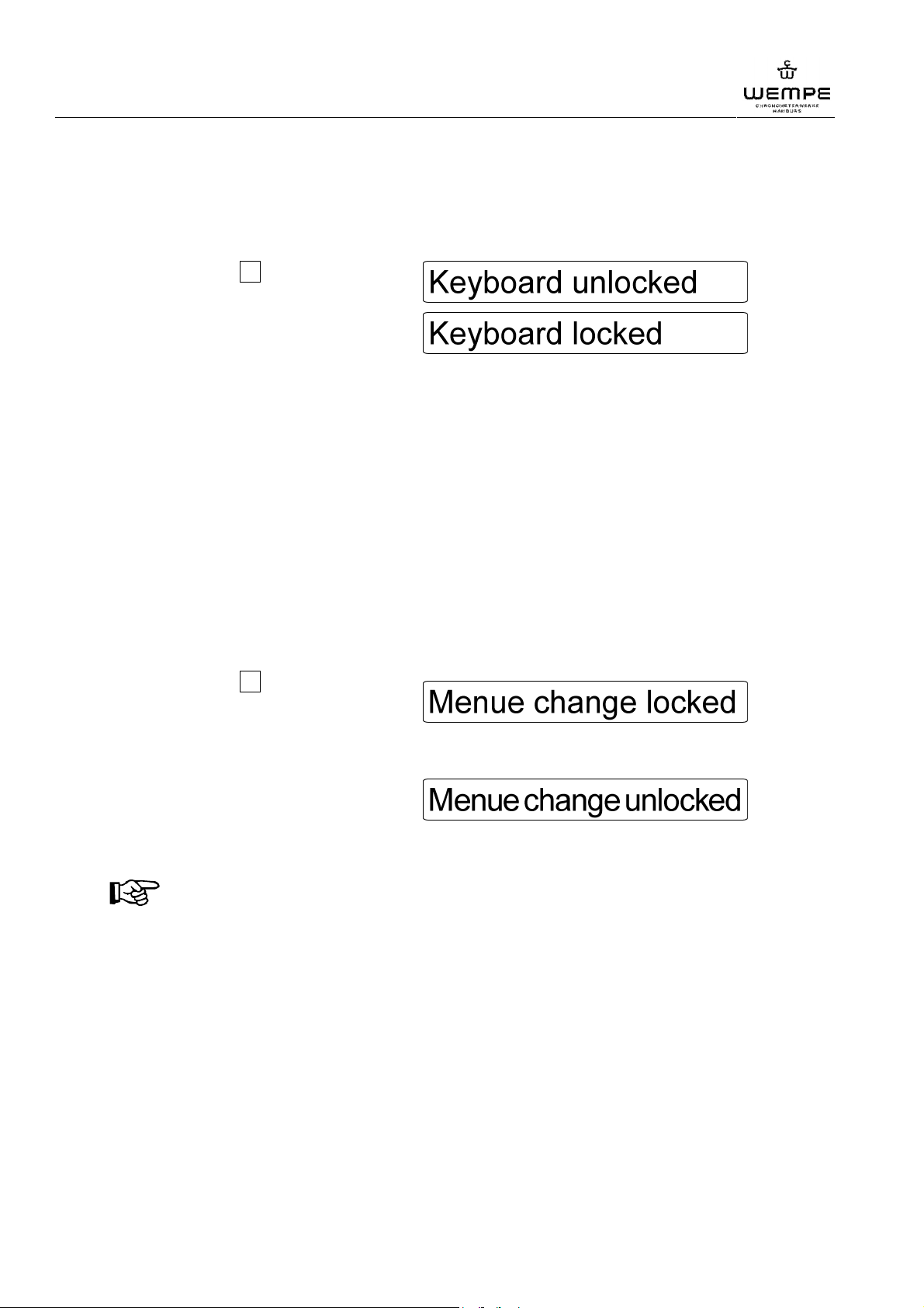
1.1.7 Lock the keyboard
In order to prevent maloperations lock the keyboard after having finished the setting.
1. Press the MENUE key for at least 4 seconds until the version number appears on the
display
2. Press the key 2 . The message on
the right appears:
3. Press the ENTER key. The message
on the right appears:
The keyboard is now locked.
4. Press the MENUE key to return to the time display.
1.2 Additional settings
1.1.1 Remove write protection for additional settings
The additional settings of the main clock are protected by a password.
The password is "345", unless a different password has been stipulated. If a different
password is pre-configured, this is indicated on a sticker on the last page of this manual.
Remove write protection:
1. Press the MENUE key for at least 4s until the version number appears on the display.
2. Press the key 1 several times until
the message on the right appears on
the display:
3. Enter the safety code to remove the write protection.
4. Press the ENTER key for
confirmation. The message on the
right appears on the display :
The write protection for the additional settings is now removed.
NOTICE!
When quitting the setting menu, the write protection is automatically activated again.
24
V3.0 01/2011
Page 25
WEMPE digital main clock 20097
Operation
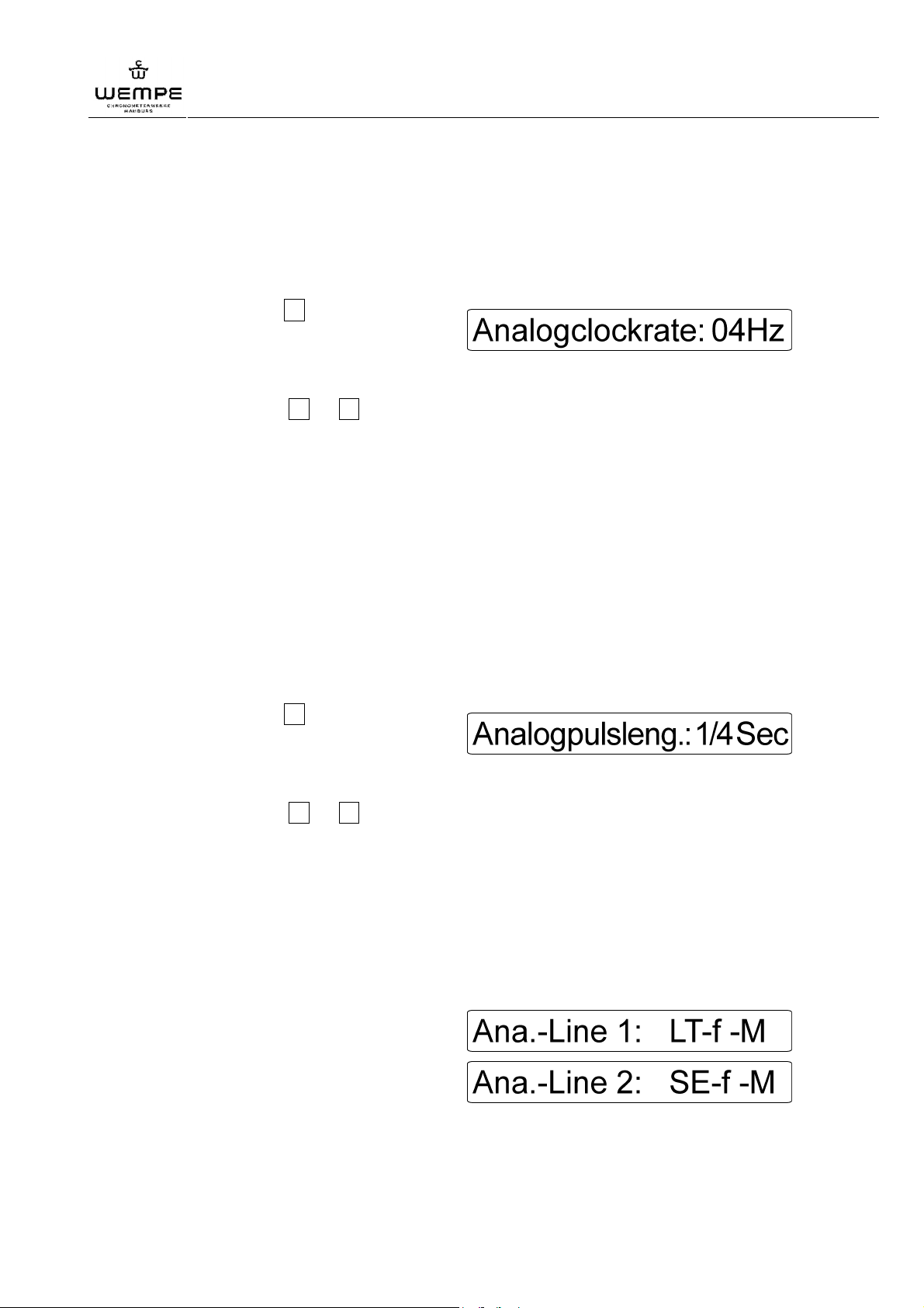
1.1.2 Setting of adjustment frequency for analogue secondary clocks
If the local time is modified, the time of the analogue secondary clocks is automatically
adjusted within short. The standard setting of the main clock is 4Hz (4 impulses per second).
Setting of the adjustment frequency:
1. Remove write protection ( 1.1.1).
2. Press the key 1 several times until
the message on the right appears on
the display:
3. Press the ENTER key for confirmation. The cursor starts flashing.
4. Press the key 1 or 2 to modify the set value gradually.
5. Press the ENTER key to confirm the modification.
To cancel the modification, press the MENUE key twice.
6. Press the MENUE key to return to the time display.
1.1.3 Setting of impulse width
The default setting upon delivery of the impulse width of the analogue lines is ¼ s (pulse
width of the output impulse = 250ms). If a higher adjustment frequency than 1/impulse width
is set, the main clock automatically limits the maximum pulse width.
Setting of the impulse width:
1. Remove write protection ( 1.1.1).
2. Press the key 1 several times until
the message on the right appears on
the display:
3. Press the ENTER key for confirmation. The cursor starts flashing.
4. Press the key 1 or 2 to modify the set value gradually.
5. Press the ENTER key to confirm the modification.
To cancel the modification, press the MENUE key twice.
6. Press the MENUE key to return to the time display.
1.1.4 Setting of analogue lines
Two analogue lines are available:
LT: local time secondary clocks
SE: seconds secondary clocks
UT: UTC secondary clocks
f: forwards running
fb: forwards and backwards running
M: minutes (or seconds) impulses
H: ½ minute (½ second) impulses
G: GORGITIME / 24-hour display
V3.0 01/2011
25
Page 26
WEMPE digital main clock 20097
Operation
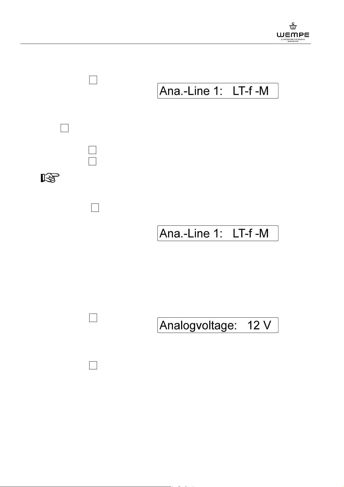
Setting of the analogue line:
1. Remove write protection ( 1.1.1).
2. Press the key 1 several times until
one of the analogue line setting
menus appears on the display, for
example:
3. Press the ENTER key for confirmation. The line number starts flashing.
(The analogue line that needs to be modified, can only be selected once again with the
key 2 if it has not been correctly selected in the main menu).
4. To make the desired settings of the analogue line:
– press the key 3 to set an UT, LT or seconds line.
– press the key 4 to merge two lines to one forwards and backwards running line.
NOTICE!
This setting option is only possible for line 1. After having merged the two lines,
settings for line 2 are no longer indicated in the main menu.
– Press the key 5 to set whether the output impulses are to be transmitted every
minute (second) "M" or every half-minute (second) "H".
Example for a forwards running
secondary clock line (local time) with
minutes impulse:
5. Press the ENTER key to confirm the modification.
To cancel the modifications, press the MENUE key twice.
6. Press the MENUE key to return to the time display.
1.1.5 Setting of secondary clocks impulse voltage
1. Remove write protection ( 1.1.1).
2. Press the key 1 several times until
the message on the right appears on
the display:
(The default setting of the main clock is 12V for the secondary clock impulses.)
3. Press the ENTER key for confirmation. The voltage value starts flashing.
4. Press the key 3 to switch between 12V and 24V.
5. Press the ENTER key to confirm the modification.
To cancel the modifications, press the MENUE key twice.
6. Press the MENUE key twice to return to the time display.
26
V3.0 01/2011
Page 27
WEMPE digital main clock 20097
Operation
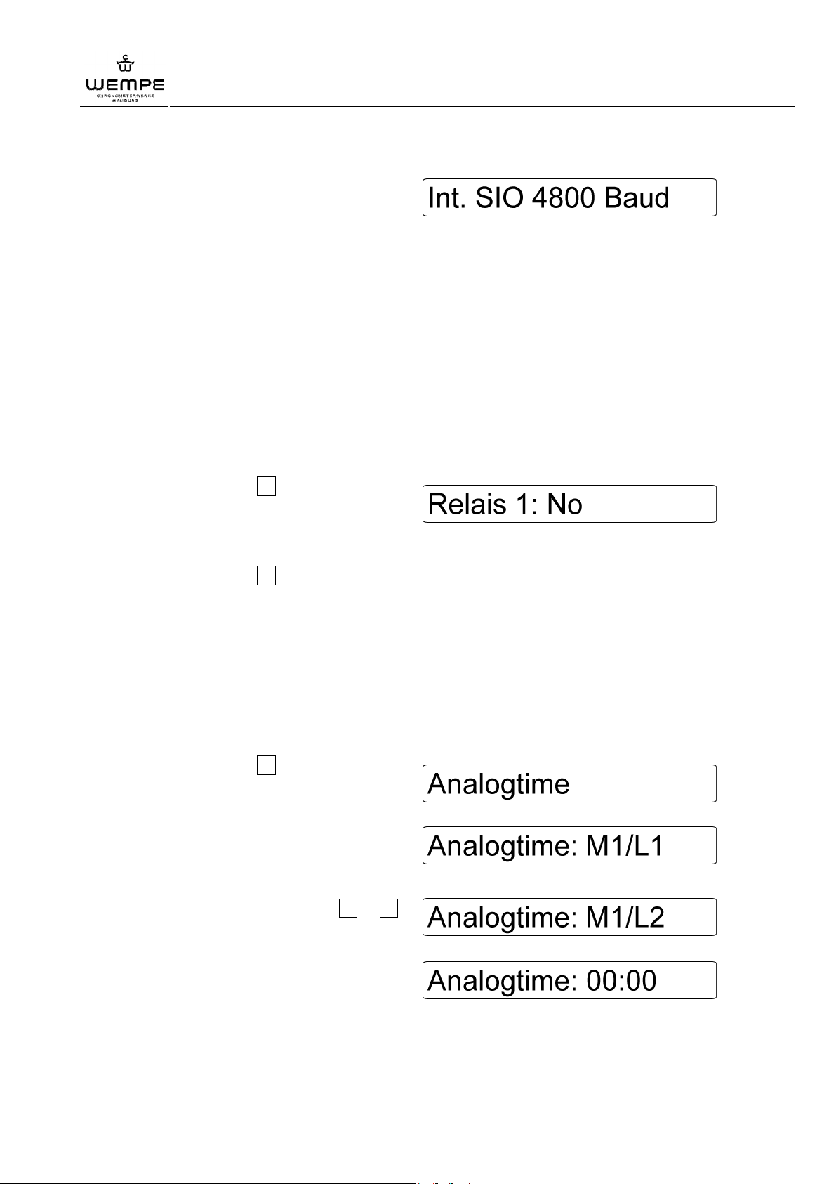
1.1.6 Setting of the internal standard interface
The default setting of the baud rate is
4800. The message on the right is
indicated for information purposes:
1.1.7 Programming of relay outputs for error messages
The main clock is fitted with 2 relay outputs that can be programmed for the following error
messages:
Supply: power supply failure (24 V DC)
Ext. Fuse: failure of the secondary clock fuse ("SLAVE")
Int. Fuse: failure of the main fuse ("MAINS")
Low Batt.: accumulator voltage too low
Programming of the relay outputs for the error messages:
1. Remove the write protection ( 1.1.1).
2. Press the key 1 several times until
one of the two relay setting menus
appears on the display, for example:
3. Press the ENTER key for confirmation. The cursor starts flashing.
4. Press the key 2 to select from among the possible errors.
5. Press the ENTER key to confirm the selection.
To cancel the modification, press the MENUE key twice.
6. Press the MENUE key, to return to the date display.
1.3 Set-up of secondary clocks
1. Press the MENUE key for at least 4 s until the version number appears on the display.
2. Press the key 2 several times until
the analogue time setting menu
appears on the display.
3. Press the ENTER key. The following
display appears (for secondary
clocks on the terminals 32 & 33):
For analogue secondary clocks on
the terminals 7 & 8, press 1 or 2
once, until the message on the right
appears on the display:
4. Press the ENTER key. The following
display appears:
5. Set all secondary clockss by hand to a standardised time (e.g. 12:00).
V3.0 01/2011
27
Page 28
WEMPE digital main clock 20097
Operation
6. Set this time in the analogue time setting menu of the main clock with the keys 8 and
9 .
7. Press the ENTER key for confirmation.
8. Press the MENUE key. The secondary clocks are synchronised automatically. The
main clock and the connected secondary clocks are now set to an standardised time.
9. Press the MENUE key again to return to the time display.
1.4 Use of extension cards
The main clock detects automatically that extension cards are inserted in the slots. Inserted
extension cards are automatically initialised and set-up according to their basic functions.
The extension card settings are also protected by the system’s password.
Depending on the used slot, the number 2 – 4 is indicated after the term "Module".
1.1.1 Extension card for digital clocks
An extension card for digital clocks needs to be installed to operate digital secondary clocks.
Both times (UTC and LT) are always transmitted via the BCD code.
The standard display of digital WEMPE secondary clocks is LT. The display can be changed
from LT to UTC manually by means of an internal jumper.
To change from the UTC date transmitted by default setting to the LT date, proceed as
follows:
1. Remove write protection ( 1.1.1).
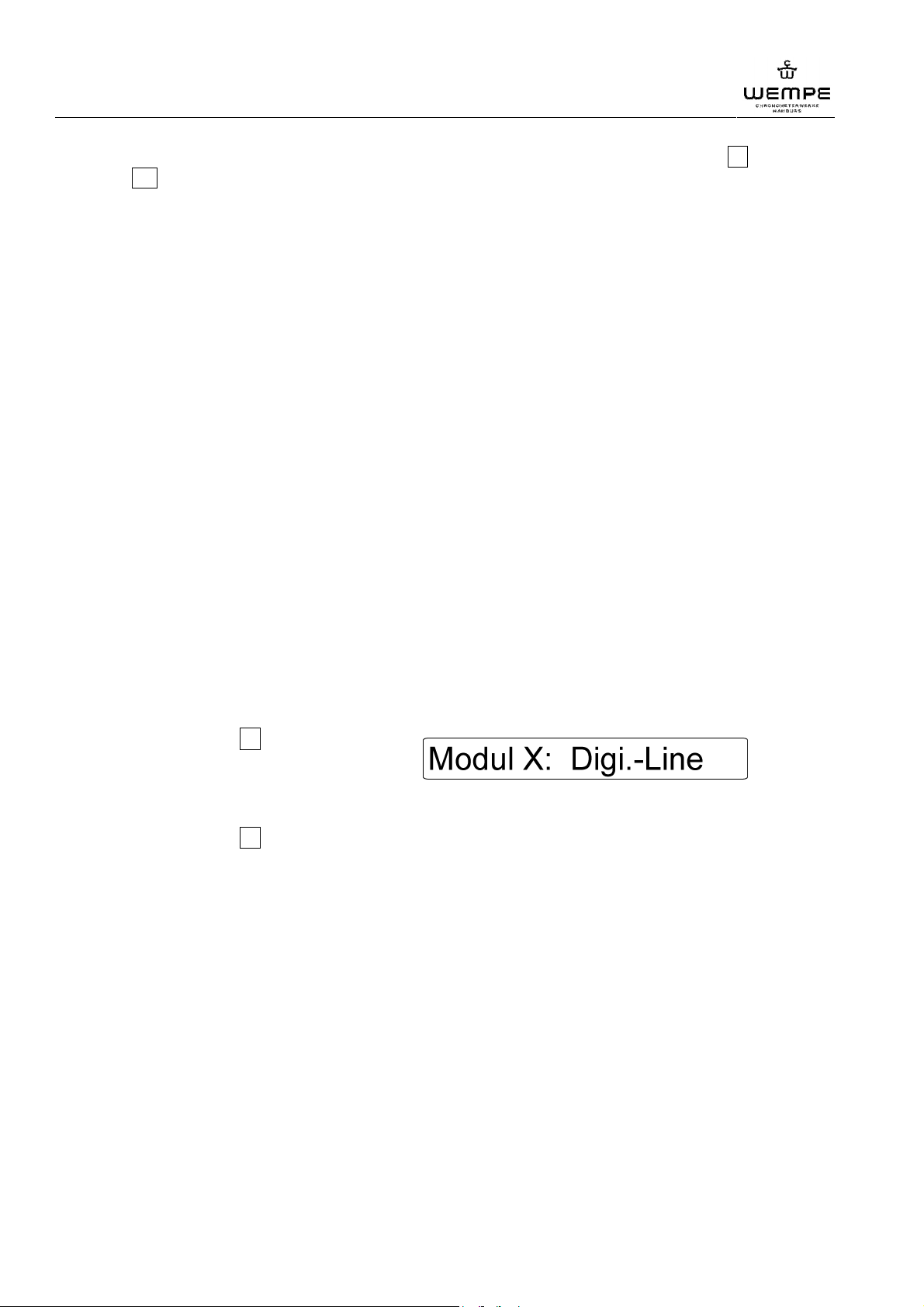
2. Press the key 1 several times until
the message on the right appears on
the display:
3. Press the ENTER key for confirmation. The cursor starts flashing.
4. Press the key 2 to select UTC or LT date.
5. Press the ENTER key to confirm the modification.
To cancel the modification, press the MENUE key twice.
6. Press the MENUE key to return to the time display.
1.1.2 MOBALine extension cards
If a MOBALine extension card for automatically adjusting secondary clocks is installed in the
unit, it is not necessary to carry out any settings for the secondary clocks.
28
V3.0 01/2011
Page 29
WEMPE digital main clock 20097
Operation
1.1.3 Extension card for analogue clocks
If an extension card for analogue clocks is installed in the unit, set the secondary clock line
as follows:
Two analogue lines are available:
LT: local time secondary clocks
SE: seconds secondary clocks
UT: UTC secondary clocks
f: forwards running
fb: forwards and backwards running
M: minutes (or seconds) impulses
H: ½ minute (½ second) impulses
G: GORGITIME / 24-hour display
Setting of the analogue line:
1. Remove write protection ( 1.1.1).
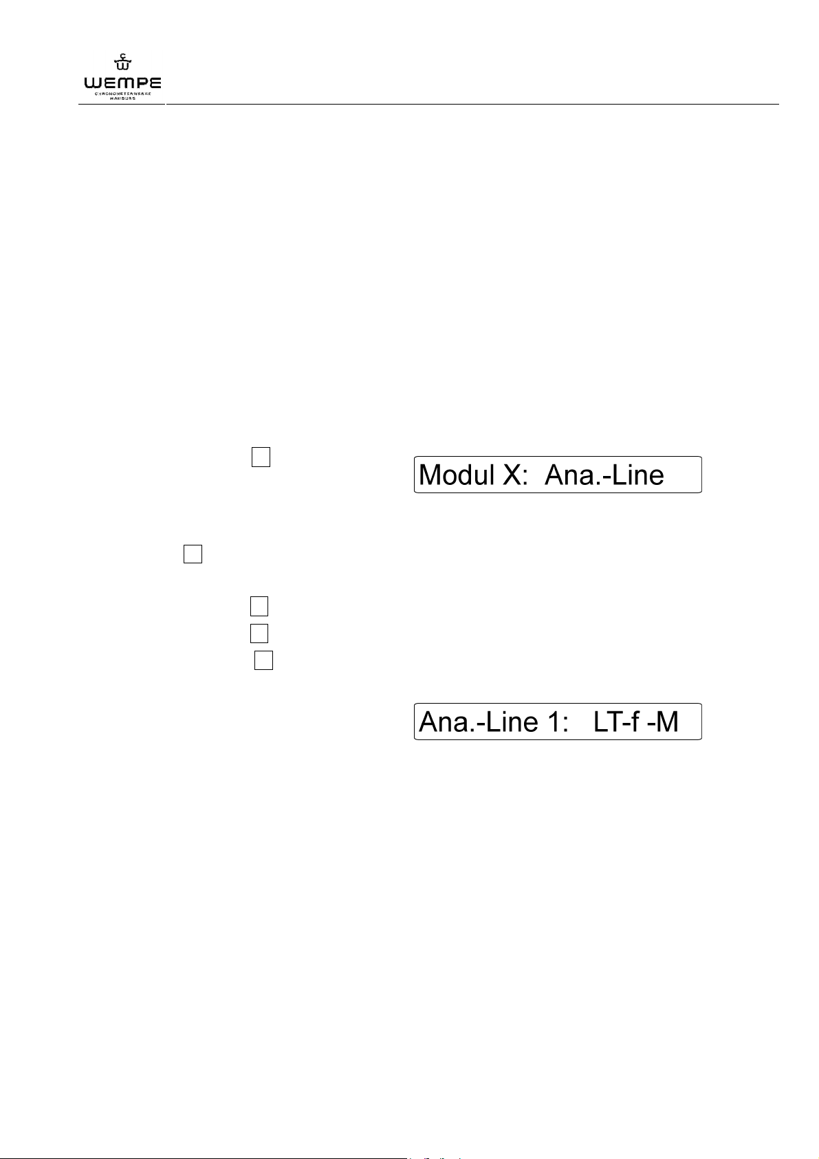
2. Press the key 1 several times until
the following message appears on
the display:
3. Press the ENTER key for confirmation. The line number starts flashing.
(The analogue line that needs to be modified, can only be selected once again with the
key 2 if it has not been correctly selected in the main menu).
4. To make the desired settings of the analogue line:
– press the key 3 to set an UT, LT or seconds line,
– press the key 4 to merge two lines to one forwards and backwards running line,
– press the key 5 to set whether the output impulses are to be transmitted every
minute (second) "M" or every half-minute (second) "H".
Example for a forwards running
secondary clock line (local time) with
minutes impulse:
5. Press the ENTER key to confirm the modification.
To cancel the modifications, press the MENUE key twice.
6. Press the MENUE key to return to the time display.
V3.0 01/2011
29
Page 30
WEMPE digital main clock 20097
Operation
1.1.4 Serial extension card
In case of an installed serial extension card, proceed as follows to set the protocol and
desired data frame:
1. Remove the write protection ( 1.1.1).
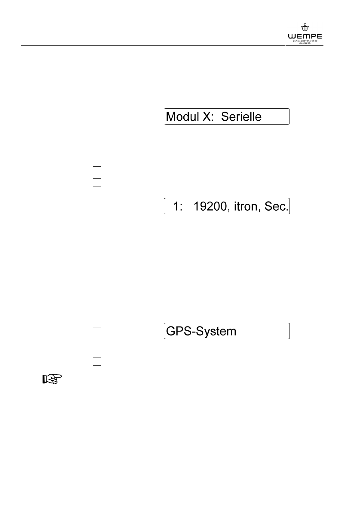
2. Press the key 1 several times until
the message on the right appears on
the display:
3. Press the ENTER key for confirmation. The cursor starts flashing.
4. Press the key 2 to switch between the two interfaces of the serial extension card.
5. Press the key 3 to set the baud rate.
6. Press the key 4 to select the protocol.
7. Press the key 5 to set whether the protocol is to be sent every minute or every
second.
Example for interface 1:
| | | |
interface baud rate protocol impulse
8. Press the ENTER key to confirm the modification.
To cancel the modifications, press the MENUE key twice.
9. Press the MENUE key to return to the time display.
1.5 Insertion of GPS receiver
1.1.1 Select GPS receiver
1. Remove write protection ( 1.1.1).
2. Press the key 1 several times until
the message on the right appears on
the display:
3. Press the ENTER key to confirm. The cursor starts flashing.
4. Press the key 2 to switch between the GPS receivers.
NOTICE!
The types "MAGNAFOX" and "LEICA" as well as other installed GPS systems are
indicated in accordance with the basic configuration.
5. Press the ENTER key to confirm the modification.
To cancel the modifications, press the MENUE key twice.
6. Press the MENUE key to return to the time display.
30
V3.0 01/2011
Page 31
WEMPE digital main clock 20097
1.1.2 Setting of baud rate
1. Refer to the documentation of the GPS receiver for the data to be set.
2. Remove write protection ( 1.1.1).
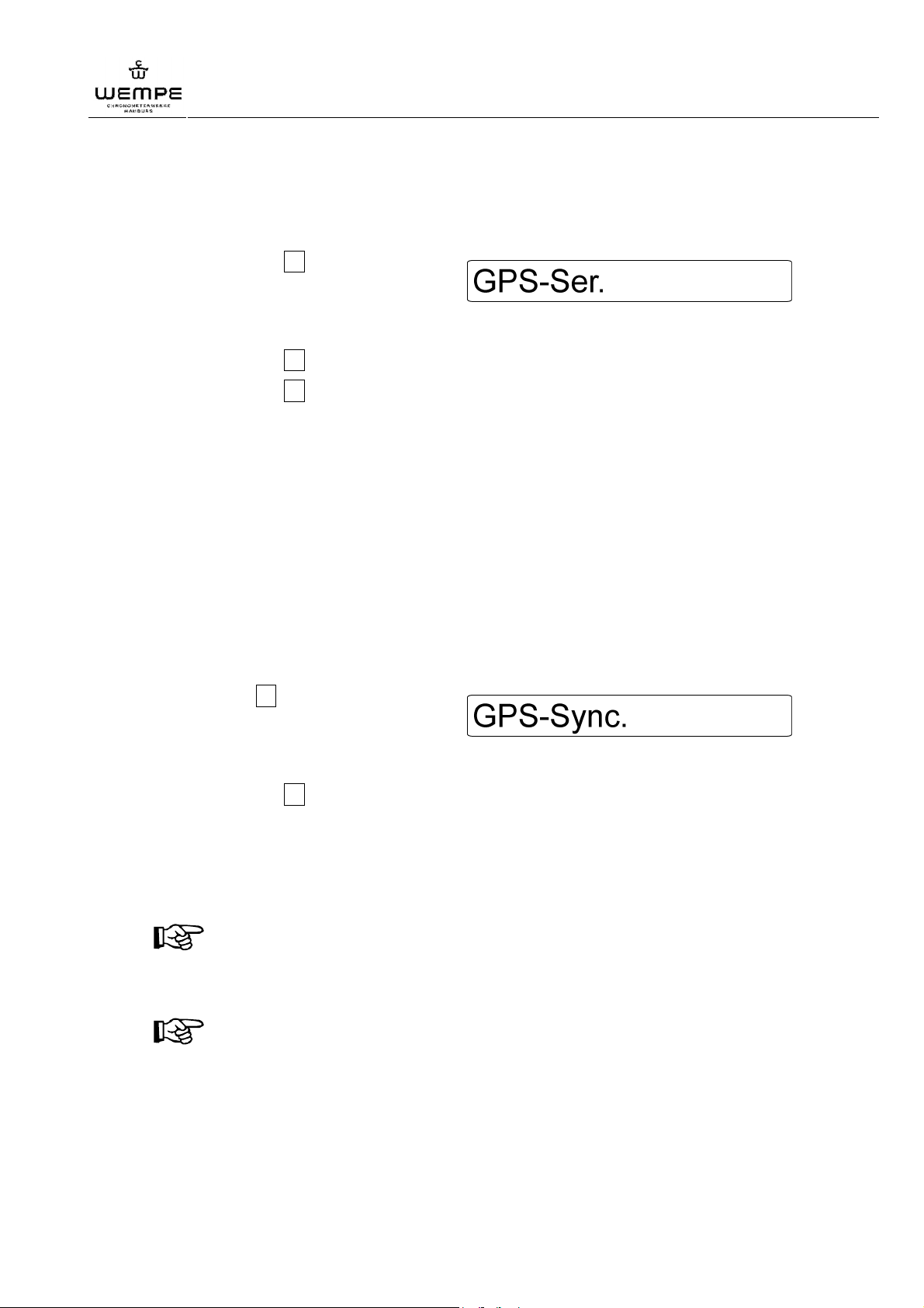
3. Press the key 1 several times until
the message on the right appears on
the display:
4. Press the ENTER key for confirmation. The cursor starts flashing.
5. Press the key 3 to set the baud rate.
6. Press the key 4 to modify the number of stop bits.
7. Press the ENTER key to confirm the modification.
To cancel the modification, press the MENUE key twice.
8. Press the MENUE key to return to the time display.
Operation
1.1.3 Synchronisation of the clock with GPS signal
The PPS signal of the GPS receiver is necessary for the exact synchronisation of the main
clock.
Additionally, a synchronisation without PPS impulse (NO PPS) can be activated for NMEA
receivers.
1. Remove write protection ( 1.1.1).
2. Press key 1 several times until the
message on the right appears on the
display:
3. Press ENTER key for confirmation. The cursor starts flashing.
4. Press the key 2 to select whether the data is to be adopted with the positive flank
(Pos.) or with the negative (Neg.) flank depending on the GPS receiver.
5. Press the ENTER key to confirm the modification.
To cancel the modifications, press the MENUE key twice.
6. Press the MENUE key to return to the time display.
NOTICE!
After having finished the settings, the main clock automatically adopts the UTC and
date. The LTC has possibly to be set by hand.
NOTICE!
In case the receiver signal is interrupted, the main clock keeps running with a high
accuracy thanks to its internal oscillator.
V3.0 01/2011
31
Page 32
WEMPE digital main clock 20097
Operation
1.1.4 Setting of synchronisation rate
The use of GPS receivers without PPS impulse involves a risk in view of the correct
synchronisation of the main clock.
All data frames that correspond to the usual layout are regarded as valid. For GPS receivers
with an up-date rate of more than 1 second, this means for example that the receiver
transmits the same time for up to 5 seconds and then makes a 5-seconds leap forwards.
This results in leaps of the time indicated on the main clock and the secondary clocks and in
some cases even a fast adjustment of the secondary clocks is carried out without interfering
of the user.
In order to eliminate this source of error, modify the synchronisation rate as follows:
1. Remove write protection ( 1.1.1).
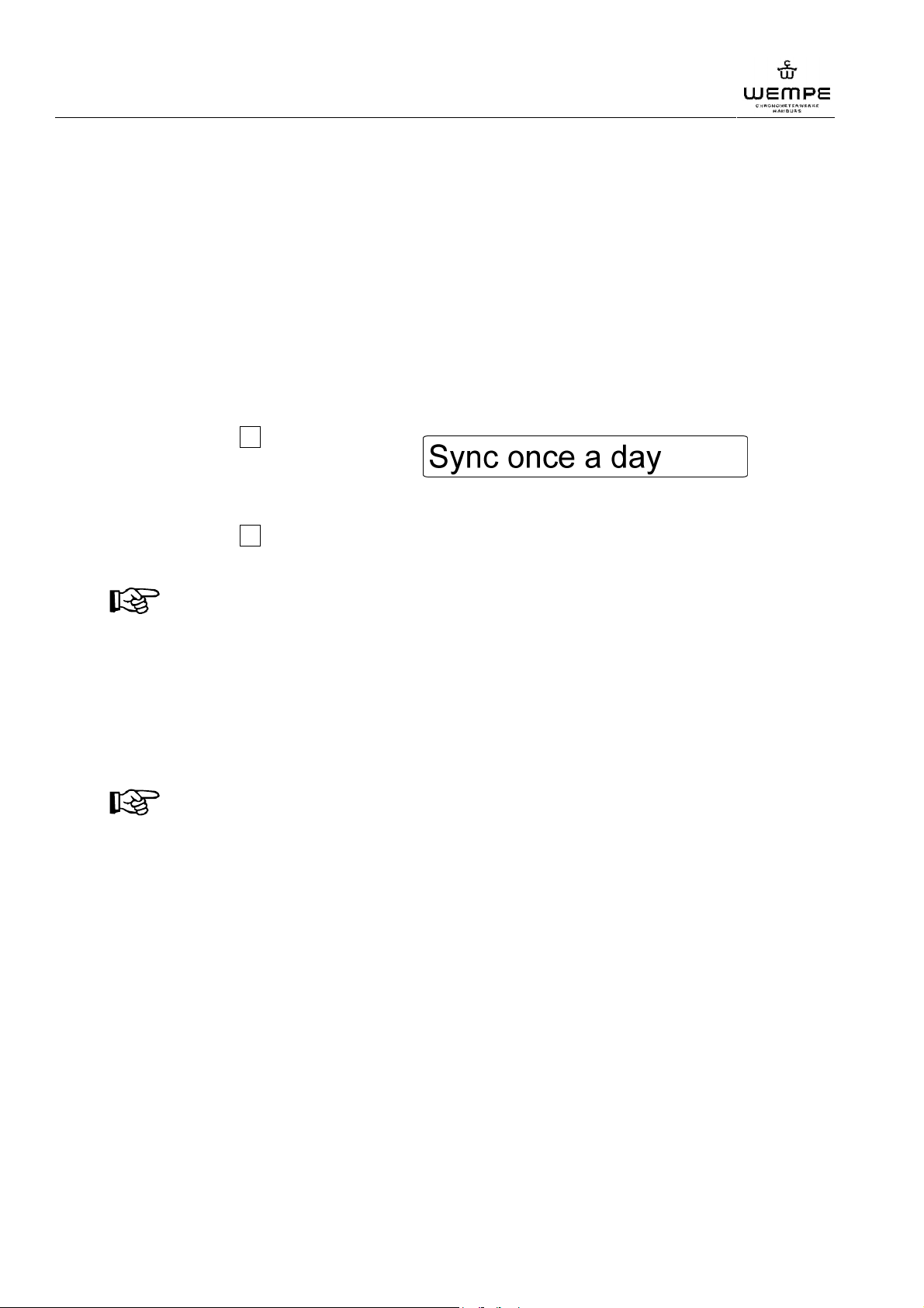
2. Press the key 1 several times until
the message on the right appears on
the display:
3. Press the ENTER key for confirmation. The cursor starts flashing.
4. Press the key 2 to set whether data is to be synchronised once per second, minute,
hour or day.
NOTICE!
During the period in between two synchronisations, the main clock runs with the
accuracy of the internal oscillator.
5. Press the ENTER key to confirm the modification.
To cancel the modifications, press the MENUE key twice.
6. Press the MENUE key to return to the date display.
NOTICE!
Although a "jumping" main clock display and fast adjustment of the secondary clocks
does not occur anymore after having modified the synchronisation rate, it is
nevertheless recommended to refit the PPS standard or to let the manufacturer of the
GPS system activate at least a higher up-date rate.
32
V3.0 01/2011
Page 33

WEMPE digital main clock 20097
1.6 Programming summary
chapter function value date signature
6.1.5 Automatic
6.1.6 Dimmer
6.2.2 Analogue Clock rate
6.2.3 Analogpulsleng.
6.2.4 Ana.-Line 1
6.2.4 Ana.-Line 2
6.2.5 Analogue Voltage
6.2.7 Relay 1
6.2.7 Relay 2
Operation
6.4.1 Module X: Digi.-Line
6.4.2 Module X: MOBALine
6.4.3 Module X: Ana.-Line
6.4.4 Module X: Serial
6.5.1 GPS-System
6.5.2 GPS-Ser.
6.5.3 GPS-Sync.
6.5.4 Sync. once a second
serial number: software version:
V3.0 01/2011
33
Page 34
WEMPE digital main clock 20097
Trouble shooting
7 Trouble shooting
Values as the external supply voltage, the accumulator supply voltage and the fuses are
automatically controlled by the main clock.
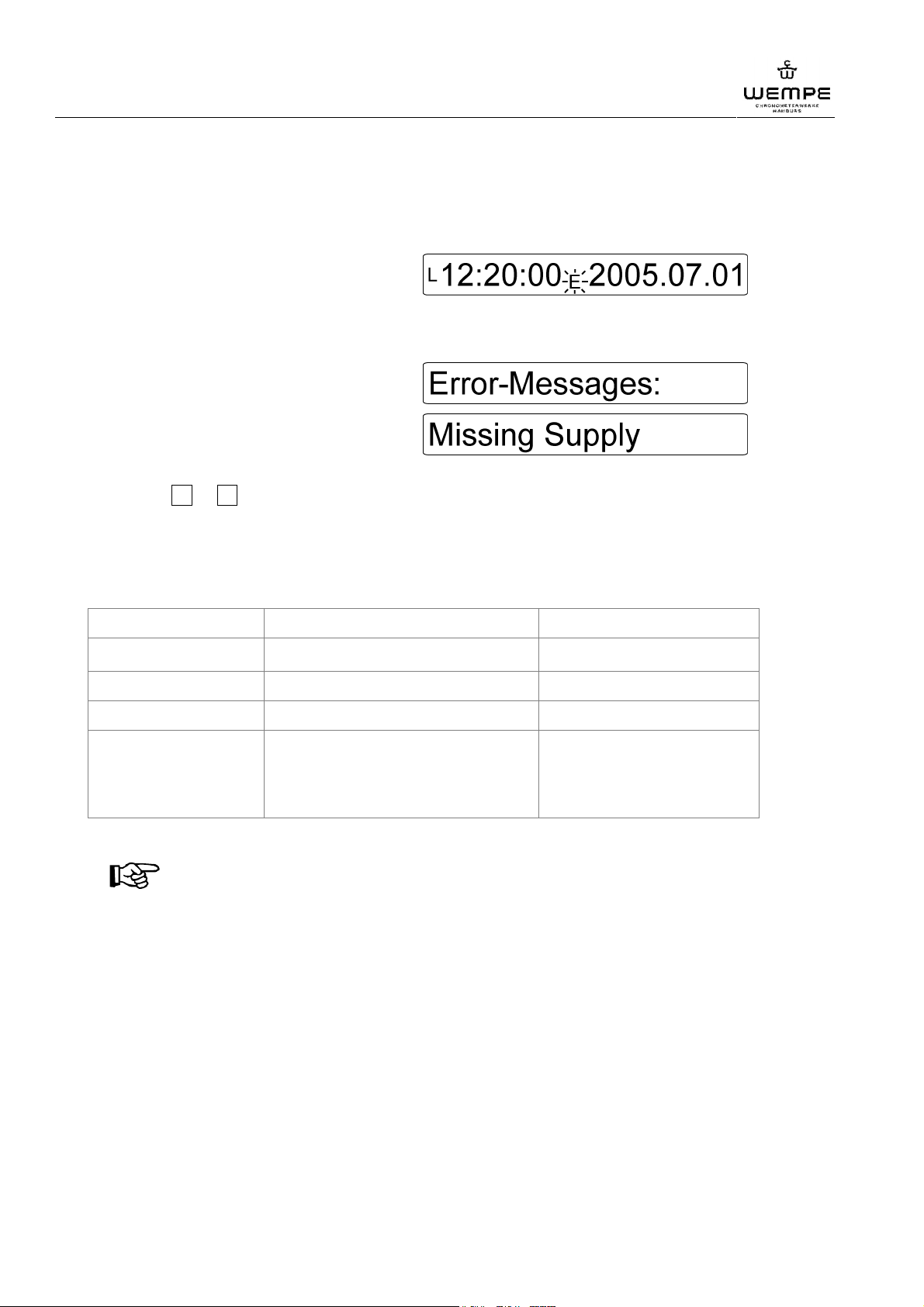
Should there be an error, the error symbol
"E" is flashing in the time display ( Ill.).
In order to have the specific error indicated:
1. Press the ENTER key and keep it pressed down.
2. Press the MENUE key with the
ENTER key pressed down, display:
3. Press the ENTER key once again.
the specific error message appears:
Should there be several error messages, switch between the messages using the
keys 1 or 2 .
4. Press the MENUE key to return to the time display.
The following error messages could be indicated. Fix the error as described in the column
"remedy":
error message* meaning remedy
"Missing Supply" breakdown of the 24 V DC power supply restore the power supply
"Internal Fuse Fault" failure of the main fuse ("MAINS") replace the main fuse
"External Fuse Fault" failure of the sec. clock fuse ("SLAVE") replace the secondary clock fuse.
"Low Batt." insufficient accumulator voltage recharge accumulator by
restoring power supply. Should
the accumulator be low again
after a short time, replace it.
*according to the basic configuration.
NOTICE!
Once the power supply is restored, the secondary clocks are automatically adapted to
the current time.
Should you encounter an error that is not shown in the above error table, please contact one
of the following service addresses :
Gerhard D. Wempe KG
Geschäftsbereich Chronometerwerke
Steinstraße 23
20095 Hamburg - Germany
phone: +49 – 40 – 33 44 8 - 199
fax: +49 – 40 – 33 44 8 – 676
e-mail: [email protected]
Internet: www.chronometerwerke.de
ITRON Elektronik
Willers OHG
Lindenstraße 2
29640 Schneverdingen - Germany
phone: +49 – 51 99 – 94 - 0
fax : +49 – 51 99 – 94 - 22
e-mail: [email protected]
Internet: www.itron.de
34
V3.0 01/2011
Page 35
WEMPE digital main clock 20097
Maintenance
8 Maintenance
The main clock is to a large extent maintenance-free. Nevertheless, it is necessary that the
user carries out the following maintenance work.
Every 3 months:
Clean the main clock with a dry textile cloth.
ATTENTION! Material risk!
Never use any chemical detergents, alcohol or abrasives for the cleaning !
Every 2 years:
Replace the internal accumulator to maintain the emergency operating features of the main
clock.
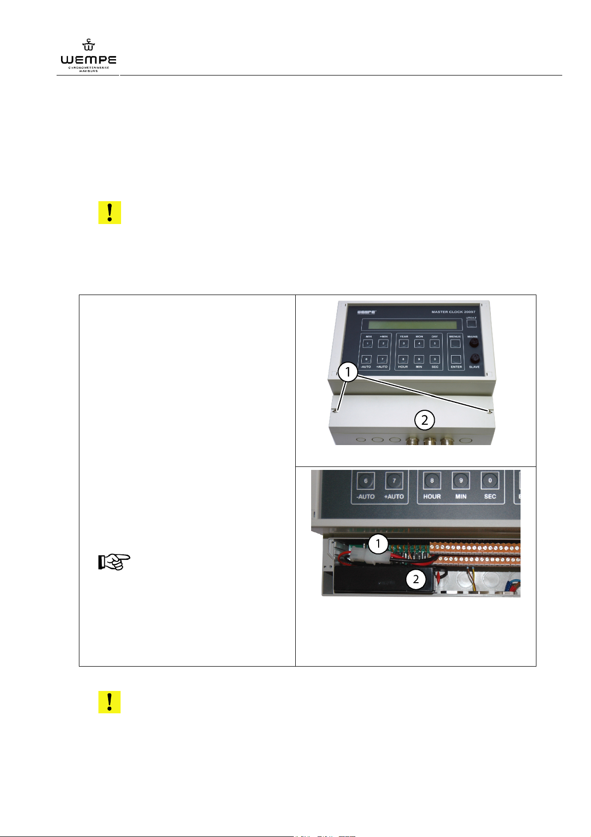
Accumulator replacement at wallmounting version:
1. Unscrew the 2 screws ( Ill. 8/1)
2. Remove the protection cover from
the terminal strip ( Ill. 8/2).
3. Unplug the connector ( Ill. 9/1).
4. Strip off the accumulator ( Ill. 9/2)
from the Velcro tape fixed on the
bottom of the case.
5. Remove the Velcro tape from the
old accumulator and stick it to the
lower part of the new accumulator.
6. Place the new accumulator in its
position and secure it on the Velcro
tape.
7. Plug the connector.
NOTICE!
It is only possible to plug the connector
if the polarity is correct.
8. Replace the cover and screw in the
screws.
Ill. 8: Terminal strip cover
Ill. 9: Accumulator and connector
9. Dispose of the old accumulator in an
environmentally friendly way.
ATTENTION! Environmental risk!
Accumulators are hazardous waste and have to be treated by approved
hazardous waste disposal sites!
V3.0 01/2011
35
Page 36
WEMPE digital main clock 20097
Maintenance
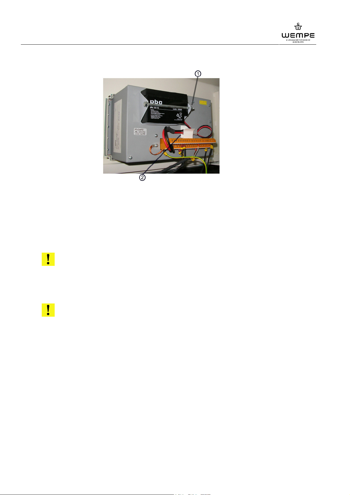
Accumulator replacement at console-mounting version:
Ill. 10 : screw and connector
1. Unscrew the screws (M4 x 110 mm) on the back of the clock.
2. Unplug the connector.
3. Replace the accumulator.
4. Plug the connector.
NOTICE!
It is only possible to plug the connector if the polarity is correct.
5. Tighten the screws.
6. Dispose of the old accumulator in an environmentally friendly way.
ATTENTION! Environmental risk!
Batteries are hazardous waste and have to be treated by approved
hazardous waste disposal sites!
After several years of use:
Give the main clock to a qualified workshop for readjustment of the oscillator. They will
readjust the oscillator by means of trimming capacitors.
36
V3.0 01/2011
Page 37
WEMPE digital main clock 20097
9 Annex
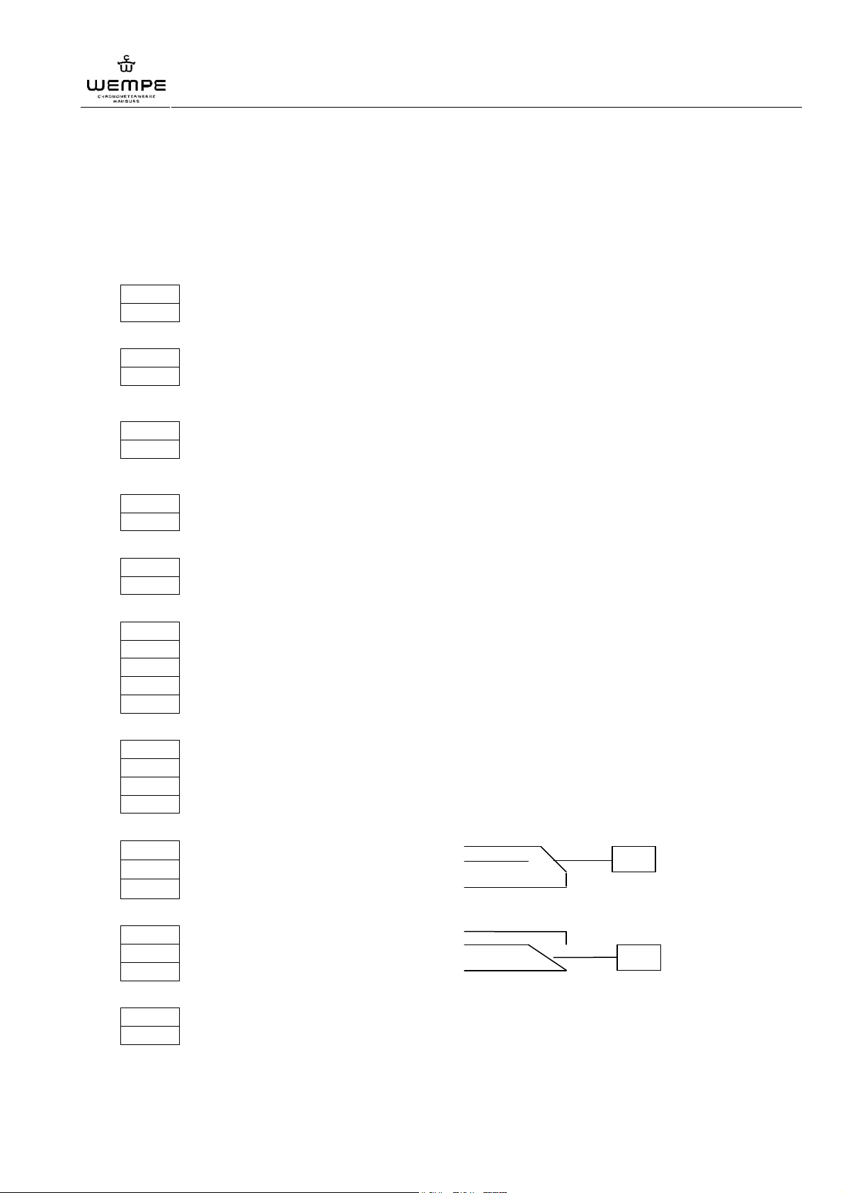
1.1 Terminal plans
1.1.1 Terminal plan for the standard version
Terminal
--- Akkumulator / accumulator + 12V
1
--- Akkumulator / accumulator 0V
2
Interne Stromversorgung
internal power supply
Annex
25
Alternativ / alternative
Alternativ / alternative
32
33
26
27
13
37
14
38
39
15
40
16
41
--- GND
3
--- GND
7
--- Analogline / analogue line 2 Sekundenimpulse Minute rückwärts
8
--- Analogline / analogue line 2 second impulse minute backwards
--- Analogline / analogue line 1 Minutenimpulse Minute vorwärts
--- Analogline / analogue line 1 minute impulse minute forwards
--- GND
--- GND
--- RS485/422 TxD+
--- RS485/422 TxD-
--- PPS+ Output
--- PPS- Output
--- GND
--- GPS-PPS-Pulse
--- GPS-PPS-GND
--- GPS-Data
--- GPS-Data-GND
21
45
46
22
23
47
24
48
V3.0 01/2011
--- Relay 1 common com
--- Relay 1 normal open no
--- Relay 1 normal close no
--- Relay 2 normal open no
--- Relay 2 normal close no
--- Relay 2 common com
--- power supply + 24V DC Stromversorgung + 24V DC
--- power supply 0V Stromversorgung 0V
37
Page 38
WEMPE digital main clock 20097
Annex
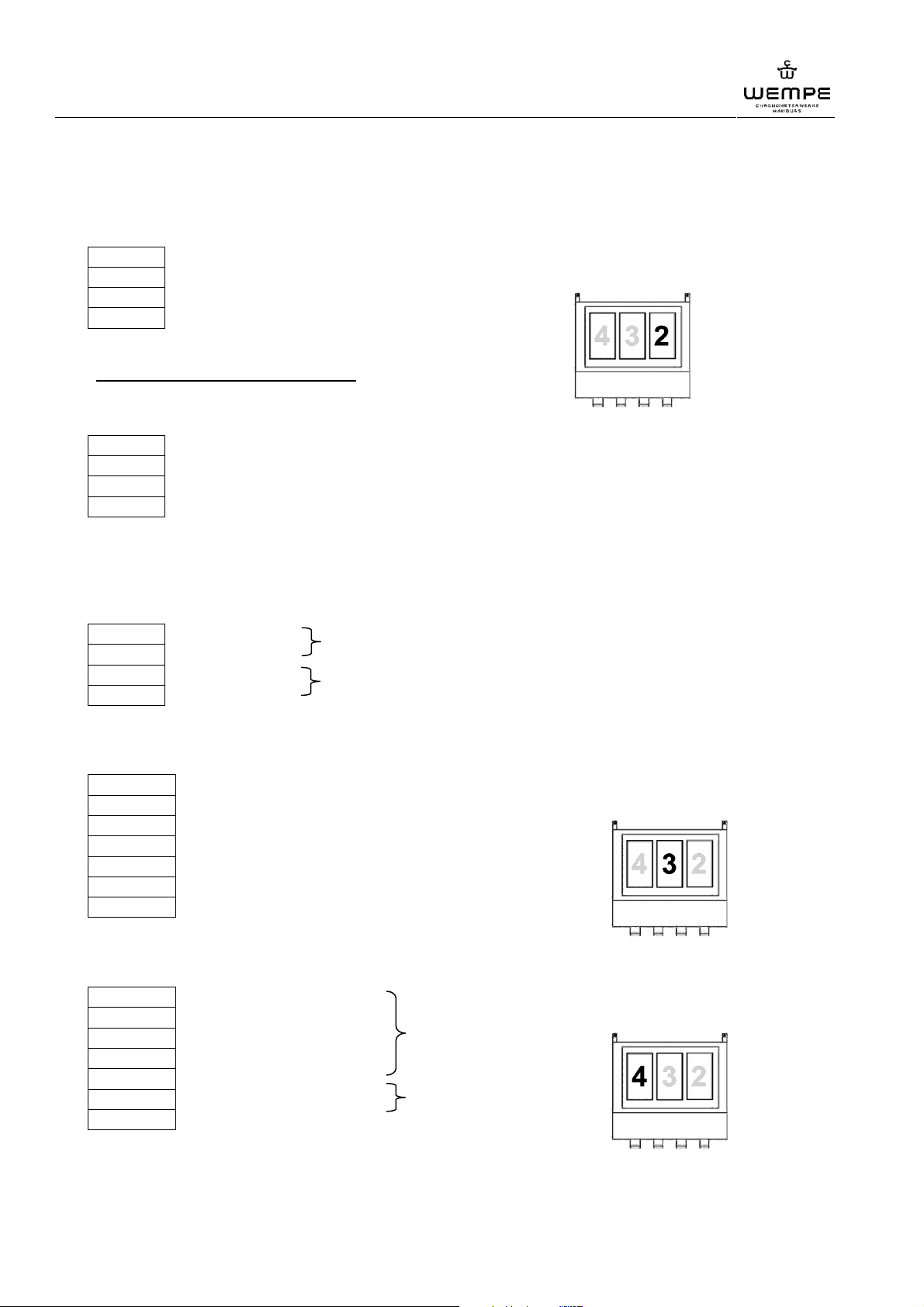
1.1.2 Terminal board of the extension cards
terminal MOBALine secondary clocks – part-no. 605 998 – 2
20
44
19
43
--- Local time line/UTC line depending on settings plug-in socket 2
--- Local time line/UTC line depending on settings
--- not used
--- not used
Alternatives for plug-in socket 2
terminal Analogue-Booster – part-mo. 605 496 - 2
19
20
43
44
--- Analogue-Line 2 – second impulse
--- Analogue-Line 2 – second impulse
--- Analogue-Line 1 – minute impulse
--- Analogue-Line 1 – minute impulse
Klemme Analogue-Booster – part-no. 605 496 - 2
forwards-/backwards running
SEIKO secondary clock systems
19
20
43
44
--- line 1 forwards
--- line 1
--- line 2 backwards
--- line 2
Digital secondary clocks – part-no. 606 198 - 0
11
12
35
36
10
34
9
--- Synchron clock plug-in socket 3
--- GND
--- Data
--- GND
--- + 24V DC
--- + 24V DC
--- 0V DC
Serial interface – part-no. 605 396 - 3
28
29
31
6
4
30
5
--- GND plug-in socket 4
--- interface 1 CTS
---------------- RS 422 + interface 1
---------------- RS 422 -
---------------- RS 232
--- interface 2 CTS interface 2
---------------- RS 232
38
V3.0 01/2011
Page 39
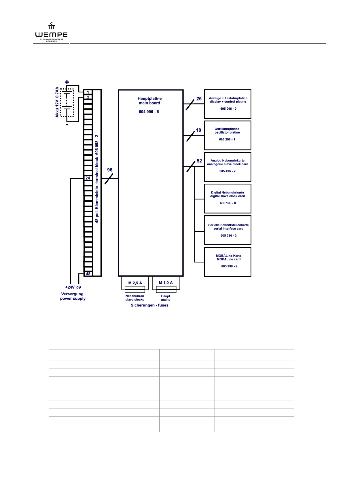
1.2 Block diagram
WEMPE digital main clock 20097
Annex
Ill. 10: Block diagram
Table of components
designation part no. comment
Main board 604 996 - 5
Display + Control board 605 096 - 0
Oscillator board 605 296 - 1
Terminal strip board 606 098 - 2 only wall-mounting version
Terminal strip board 606 098P - 1 only console-mount. vers.
SIO Serial In-OUT board 605 396 - 3 optional
Digital secondary clock out board 606 198 - 0 optional
Analogue slave clock out board 605 496 - 2 optional
MOBALine out board 605 998 - 2 optional
V3.0 01/2011
39
Page 40
WEMPE digital main clock 20097
Annex
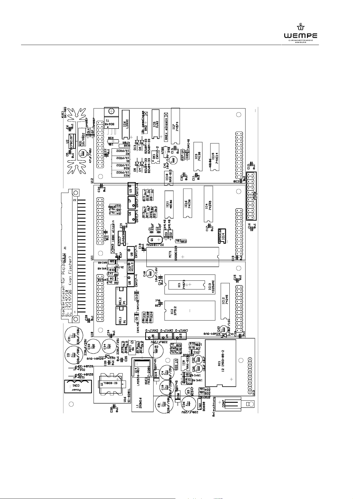
1.3 Circuit boards
1.1.1 Main board
Ill. 11: Main board
40
V3.0 01/2011
Page 41
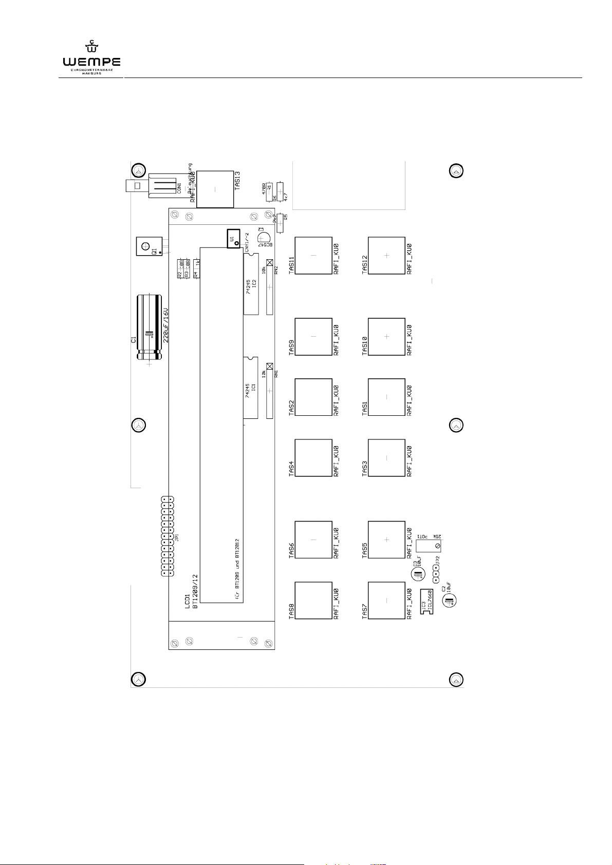
1.1.2 Display and control board
WEMPE digital main clock 20097
Annex
Ill. 12: Display and control board
V3.0 01/2011
41
Page 42
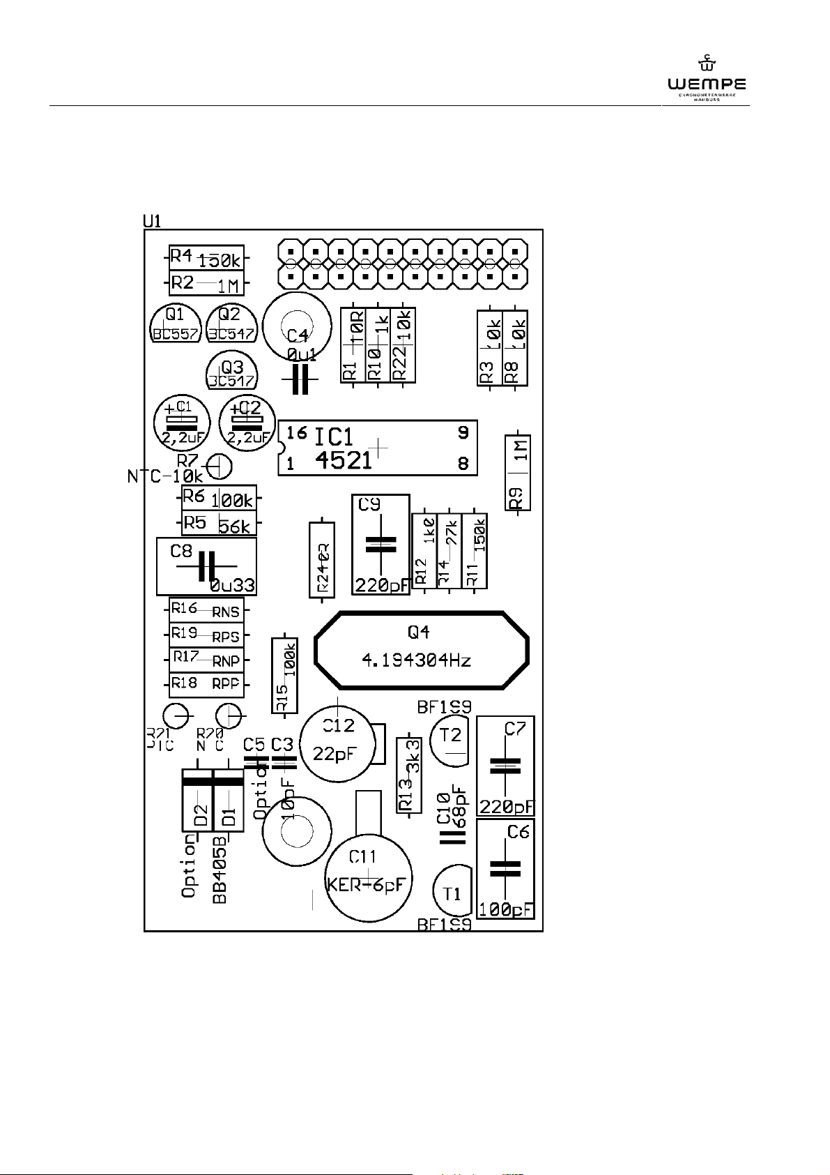
WEMPE digital main clock 20097
Annex
1.1.3 Oscillator board
Ill. 13: Oscillator board
42
V3.0 01/2011
Page 43
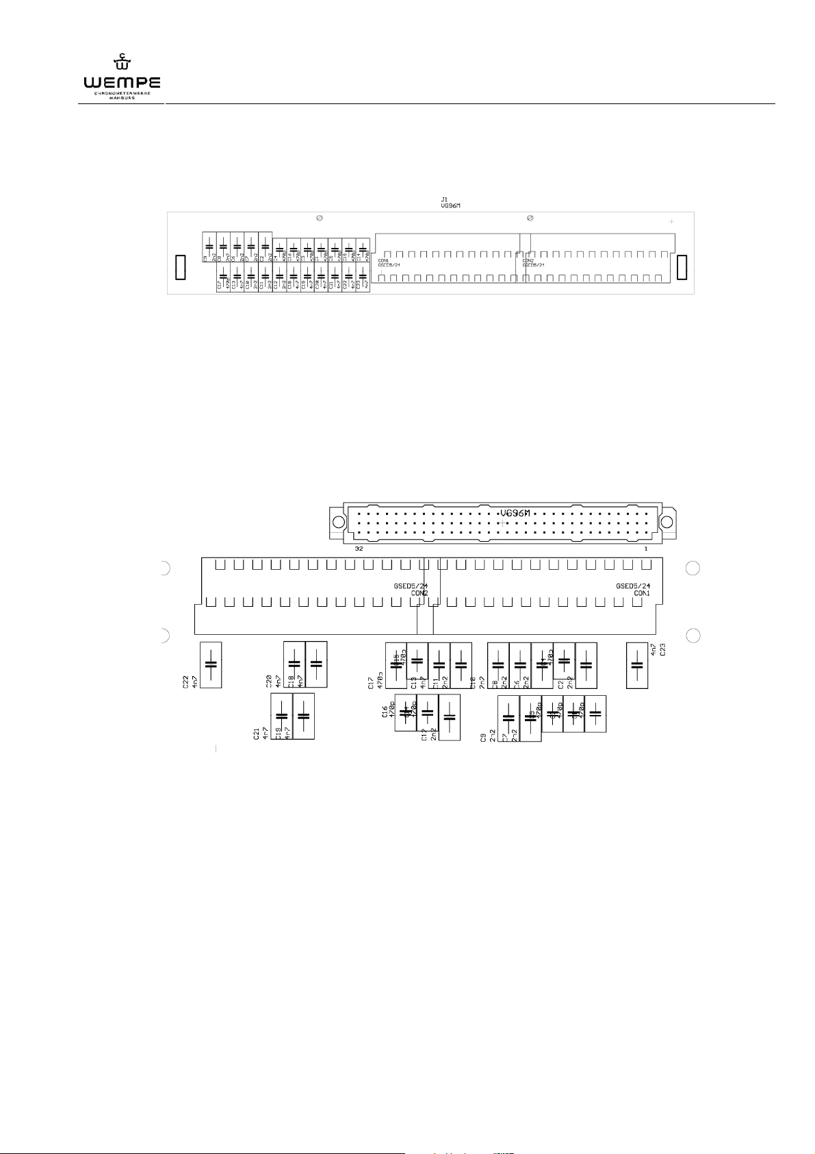
WEMPE digital main clock 20097
1.1.4 Terminal strip board (wall-mounting version)
Ill. 14: Terminal strip board (wall-mounting version)
1.1.5 Terminal strip board (console-mounting version)
Annex
V3.0 01/2011
Ill. 15: Terminal strip board (console-mounting version)
43
Page 44
WEMPE digital main clock 20097
Annex
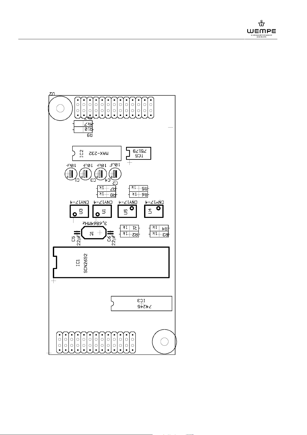
1.4 Extension cards
1.1.1 SIO Serial interface in-out board (optional)
Ill. 16: SIO serial interface in-out board (optional)
44
V3.0 01/2011
Page 45
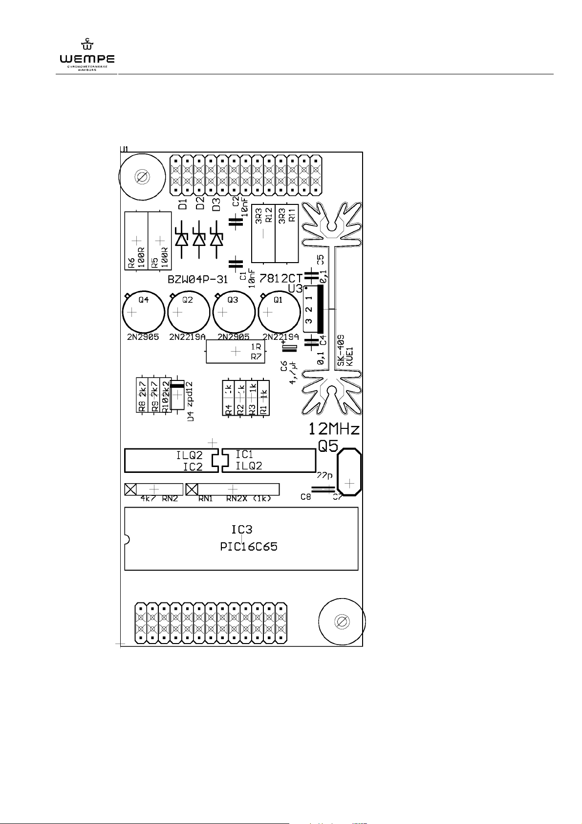
WEMPE digital main clock 20097
1.1.2 Digital secondary clocks extension card - – out (optional)
Annex
Ill. 17: Digital secondary clock out board (optional)
V3.0 01/2011
45
Page 46
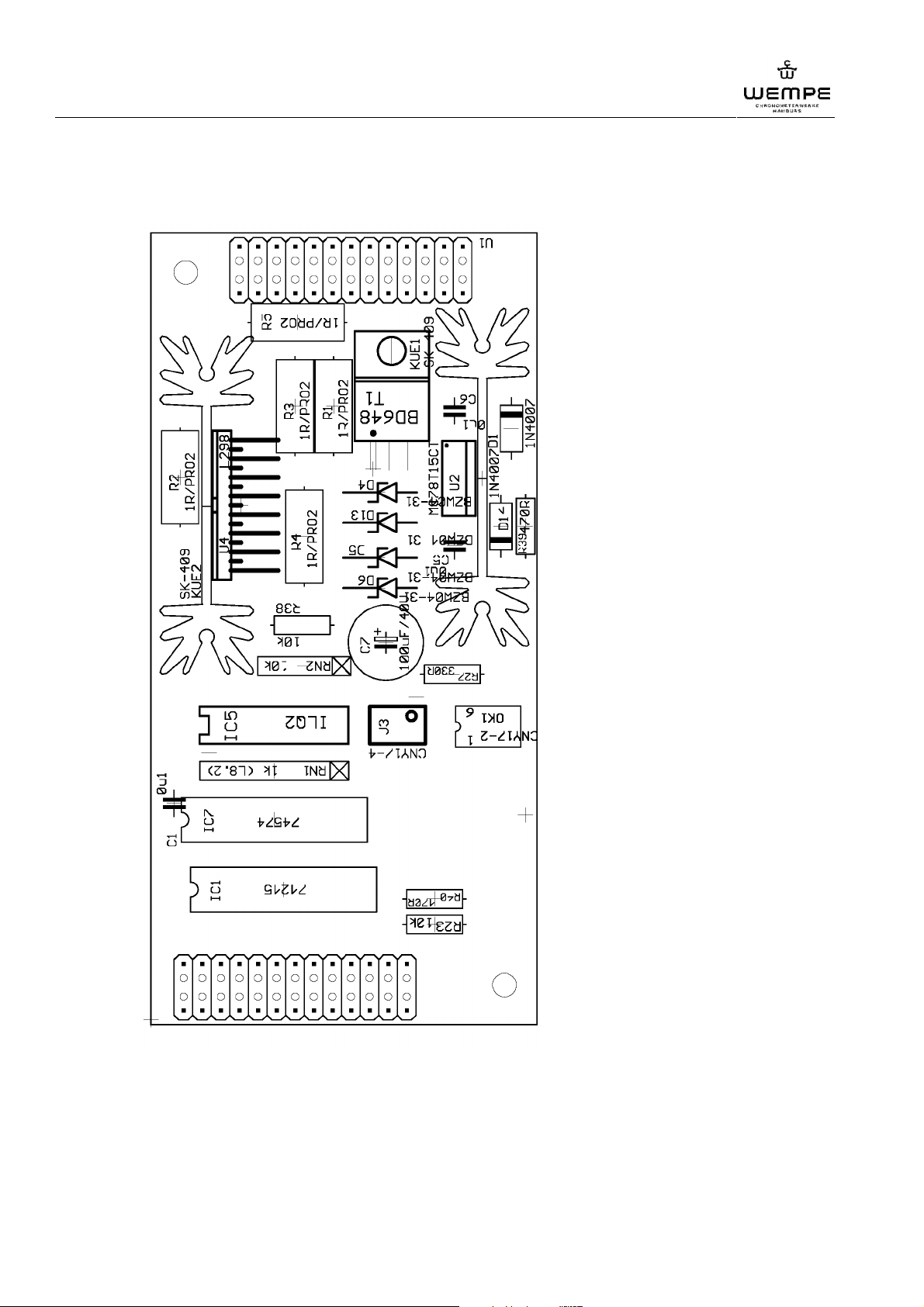
WEMPE digital main clock 20097
Annex
1.1.3 Analogue secondary clocks extension card – out (optional)
Ill. 18: Analogue slave clock out board (optional)
46
V3.0 01/2011
Page 47
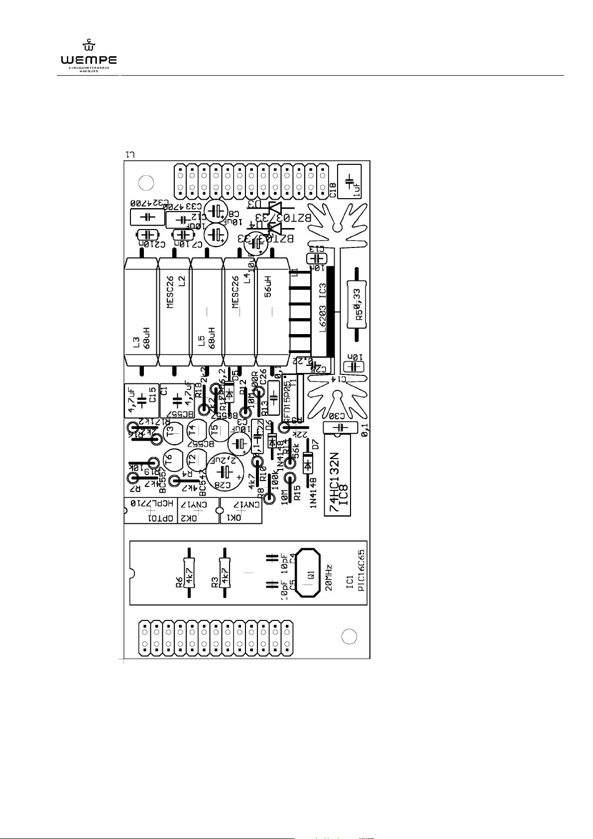
WEMPE digital main clock 20097
1.1.4 MOBALine secondary clocks extension card – out (optional)
Annex
V3.0 01/2011
Ill. 19: MOBALine secondary clock out board (optional)
47
Page 48

WEMPE digital main clock 20097
Annex
1.5 Interface protocols
1.1.1 Standard protocol main clock 20097 (terminal 13 / 37)
Data scope: 1 Start bit
8 Data bit
1 Parity bit (even)
2 Stop bit
4.800 Baud
transmission once a second
Byte Mark Description
1 STX HEX02 Start of text
2 U HEX55 Data transmission of the UTC-time
3 10h Hour ten
4 1h Hour one
5 10m Minute ten
6 1m Minute one
7 10s Second ten
8 1s Second one
9 D HEX44 Data transmission of the UTC-date
10 10d Day ten
11 1d Day one
12 10m Month ten
13 1m Month one
14 1000y Year thousand
15 100y Year hundred
16 10y Year ten
17 1y Year one
18 L HEX4C Data transmission of the LT-time
19 10h Hour ten
20 1h Hour one
21 10m Minute ten
22 1m Minute one
23 10s Second ten
24 1s Second one
25 D HEX44 Data transmission of the LT-date
26 10d Day ten
27 1d Day one
28 10m Month ten
29 1m Month one
30 1000y Year thousand
31 100y Year hundred
32 10y Year ten
33 1y Year one
34 LF HEX0A Line feed
35 CR HEX0D Carriage return
36 ETX HEX03 End of text
48
V3.0 01/2011
Page 49

WEMPE digital main clock 20097
1.1.2 Protocol ITRON Interface RS422/485
Data scope: 1 Start bit
7 Data bit
1 Parity bit (even)
2 Stop bit
4.800 Baud
transmission once a second
Byte Mark Description
1 STX HEX02 Start of text
2 U HEX55 Data transmission of the UTC-time
3 10h Hour ten
4 1h Hour one
5 10m Minute ten
6 1m Minute one
7 10s Second ten
8 1s Second one
9 D HEX44 Data transmission of the UTC-date
10 10d Day ten
11 1d Day one
12 10m Month ten
13 1m Month one
14 10y Year ten
15 1y Year one
16 L HEX4C Data transmission of the LT-time
17 10h Hour ten
18 1h Hour one
19 10m Minute ten
20 1m Minute one
21 10s Second ten
22 1s Second one
23 D HEX44 Data transmission of the LT-date
24 10d Day ten
25 1d Day one
26 10m Month ten
27 1m Month one
28 10y Year ten
29 1y Year one
30 LF HEX0A Line feed
31 CR HEX0D Carriage return
32 ETX HEX03 End of text
Annex
V3.0 01/2011
49
Page 50

WEMPE digital main clock 20097
Annex
1.1.3 Protocol ITRON 2000 Interface RS422/485
Data scope: 1 Start bit
7 Data bit
1 Parity bit (even)
2 Stop bit
4.800 Baud
transmission once a second
Byte Mark Description
1 STX HEX02 Start of text
2 U HEX55 Data transmission of the UTC-time
3 10h Hour ten
4 1h Hour one
5 10m Minute ten
6 1m Minute one
7 10s Second ten
8 1s Second one
9 D HEX44 Data transmission of the UTC-date
10 10d Day ten
11 1d Day one
12 10m Month ten
13 1m Month one
14 1000y Year thousand
15 100y Year hundred
16 10y Year ten
17 1y Year one
18 L HEX4C Data transmission of the LT-time
19 10h Hour ten
20 1h Hour one
21 10m Minute ten
22 1m Minute one
23 10s Second ten
24 1s Second one
25 D HEX44 Data transmission of the LT-date
26 10d Day ten
27 1d Day one
28 10m Month ten
29 1m Month one
30 1000y Year thousand
31 100y Year hundred
32 10y Year ten
33 1y Year one
34 LF HEX0A Line feed
35 CR HEX0D Carriage return
36 ETX HEX03 End of text
50
V3.0 01/2011
Page 51

1.1.4 Protocol NMEA $ZCZDA
Data scope: 1 Start bit
7 Data bit
1 Parity bit (even)
2 Stop bit
4.800 Baud
transmission once a second
Byte Mark Description
1 $ HEX24
2 Z HEX5A
3 C HEX43
4 Z HEX5A
5 D HEX44
6 A HEX41
7 , HEX2C
8 10h Hour ten
9 1h Hour one
10 10m Minute ten
11 1m Minute one
12 10s Second ten
13 1s Second one
14 . HEX2E
15 1/10s Second tenth
16 1/100s Second hundredth
17 , HEX2C
18 10d Day ten
19 1d Day one
20 , HEX2C
21 10m Month ten
22 1m Month one
23 , HEX2C
24 1000y Year thousand
25 100y Year hundred
26 10y Year ten
27 1y Year one
28 , HEX2C
29 Dif. 10h Difference hour ten
30 Dif. 1h Difference hour one
31 , HEX2C
32 Dif. 10m Difference minute ten
33 Dif. 1m Difference minute one
34 * HEX2A
35 CS Z numeral or 30..39
36 CS E letter or 41..46
37 CR HEX0D Carriage return
38 LF HEX0A Line feed
WEMPE digital main clock 20097
Annex
V3.0 01/2011
51
Page 52

WEMPE digital main clock 20097
Annex
1.1.5 Protocol ECHO
Data scope: 1 Start bit
7 Data bit
1 Parity bit (even)
2 Stop bit
4.800 Baud
transmission once a second
Byte Mark Description
1 LF HEX0A Line feed
2 LF HEX0A Line feed
3 NUL
4 NUL
5 NUL
6 NUL
7 NUL
8 NUL
9 NUL
10 NUL
11 NUL
12 NUL
13 G HEX47 Data transmission of the UTC-time
14 10h Hour ten
15 1h Hour one
16 10m Minute ten
17 1m Minute one
18 10s Second ten
19 1s Second one
20 L HEX4C Data transmission of the LT-time
21 10h Hour ten
22 1h Hour one
23 10m Minute ten
24 1m Minute one
25 10s Second ten
26 1s Second one
27 D HEX44 Data transmission of the UTC-date
28 10d Day ten
29 1d Day one
30 10m Month ten
31 1m Month one
32 10y Year ten
33 1y Year one
34 CR HEX0D Carriage return
52
V3.0 01/2011
Page 53

1.1.6 Protocol IMA51
Data scope: 1 Start bit
7 Data bit
1 Parity bit (even)
2 Stop bit
4.800 Baud
transmission once a second
Byte Mark Description
1 STX HEX02 Start of text
2 10h Hour ten LT
3 1h Hour one LT
4 10m Minute ten LT
5 1m Minute one LT
6 10s Second ten LT
7 1s Second one LT
8 10h Hour ten UTC
9 1h Hour one UTC
10 10m Minute ten UTC
11 1m Minute one UTC
12 10d Day ten
13 1d Day one
14 10m Month ten
15 1m Month one
16 10y Year ten
17 1y Year one
18 CR HEX0D Carriage return
19 LF HEX0A Line feed
WEMPE digital main clock 20097
Annex
V3.0 01/2011
53
Page 54

WEMPE digital main clock 20097
Annex
1.1.7 Protocol GORGI
Data scope: 1 Start bit
7 Data bit
1 Parity bit (even)
2 Stop bit
4.800 Baud
transmission once a second
Byte Mark Description
1 STX HEX02 Start of text
2 weekday
3 weekday
4 weekday
5 SPACE HEX20
6 10d Day ten
7 1d Day one
8 / HEX2F
9 10m Month ten
10 1m Month one
11 / HEX2F
12 10y Year ten
13 1y Year one
14 SPACE HEX20
15 SPACE HEX20
16 10h Hour ten
17 1h Hour one
18 : HEX3A
19 10m Minute ten
20 1m Minute one
21 : HEX3A
22 10s Second ten
23 1s Second one
24 CR HEX0D Carriage return
25 NUL HEX00
54
V3.0 01/2011
Page 55

1.1.8 Protocol MITEL
Data scope: 1 Start bit
7 Data bit
1 Parity bit (even)
2 Stop bit
4.800 Baud
transmission only if time is set up anew
Byte Mark Description
1 ESC HEX1B
2 1
3 M
4 A
5 I
6 N
7 T
8 1
9 CR HEX0D Carriage return
10 S
11 X
12 2
13 0
14 0
15 0
16 CR HEX0D Carriage return
17 ESC HEX1B
18 6
19 T
20 I
21 M
22 E
23 SPACE HEX20
24 10h Hour ten LT
25 1h Hour one LT
26 : HEX3A
27 10m Minute ten LT
28 1m Minute one LT
29 CR HEX0D Carriage return
30 D HEX44
31 E HEX45
32 S HEX53
33 K HEX4B
34 CR HEX0D Carriage return
35 ESC HEX1B
36 1 HEX1B
WEMPE digital main clock 20097
Annex
V3.0 01/2011
55
Page 56

WEMPE digital main clock 20097
Annex
Modification history
consecutive
modification
number
date modified
page
type of modification
00 01.07.1997 first edition
01 01.07.1999 all revision
02 01.08.2001 15 determination of the baud rate
03 01.03.2004 all complete revision
01.03.2004 28-35 addition of the circuit diagram
01.03.2004 36-43 addition of the interface protocols
04 01.04.2004 13 addition of the adjustment of impulse width
05 01.06.2004 20 addition of the adjustment of synchronisation
rate
06 01.06.2004 45 addition of the programming summary
07 01.07.2005 all complete revision by Messrs. Kothes!
08 31.01.2011 all Software update 3.0
56
V3.0 01/2011
Page 57

WEMPE digital main clock 20097
A
Accessories ...........................................14
Accumulator...........................................14
Accumulator replacement ......................35
Additional circuit boards.........................14
Adjustment frequency for secondary
clocks.................................................25
Adjustment of display illumination ..........23
B
Basic settings ........................................22
Block diagram........................................39
C
Circuit boards ........................................40
Cleaning ................................................35
Connection of GPS receiver...................20
Connection of secondary clocks ............20
Console mounting..................................18
D
Design and function ...............................12
Display illumination on/off ......................23
Disposal...................................................8
E
Electrical connection..............................19
Explanation of the symbols ......................6
Extension cards ......................... 14, 28, 44
F
Fitting of cables......................................18
Front panel ............................................12
Front view..............................................12
Fuses.....................................................15
G
Guarantee................................................7
Annex
I
Insert GPS receiver ............................... 30
Installation....................................... 16, 17
Installation and operating staff............... 10
Intended use ........................................... 9
Interface protocols................................. 48
Interfaces .............................................. 11
L
Liability .................................................... 7
Lock the keyboard................................. 24
M
Maintenance.......................................... 35
O
Operation .............................................. 22
Operator’s responsibility........................ 10
Oscillator ............................................... 11
Oscillator, readjustment......................... 36
P
Packaging ............................................... 8
Power reserve ....................................... 11
Power supply......................................... 11
Programming of relay outputs................ 27
Programming summary ......................... 33
Putting into operation............................. 21
Q
Qualified staff ........................................ 10
R
Remove write protection........................ 24
Requirements on the place of installation
.......................................................... 16
V3.0 01/2011
57
Page 58

WEMPE digital main clock 20097
Annex
S
Safety ..................................................... 9
Select indicated time............................. 22
Service addresses ................................ 34
Setting of analogue lines....................... 25
Setting of automatic time adjustment .... 23
Setting of date....................................... 23
Setting of impulse width ........................ 25
Setting of time....................................... 22
Storage ................................................... 8
System overview................................... 13
T
Technical Data ......................................11
Terminal plans....................................... 37
Trained staff .......................................... 10
Transport................................................. 7
Trouble shooting.................................... 34
U
Unlock the keyboard.............................. 22
Use of extension cards.......................... 28
W
Wall mounting........................................ 17
58
V3.0 01/2011
Page 59

WEMPE digital main clock 20097
Notice
Notice
V3.0 01/2011
59
Page 60

Maritime precision at it’s best!
Gerhard D. Wempe KG
Division Chronometerwerke
Steinstr. 23 20095 Hamburg Germany
P: +49 (0) 40 / 33 44 8 – 899 F: +49 (0) 40 / 33 44 8 - 676
E: [email protected] I: www.chronometerwerke-maritim.de
 Loading...