

Welotec DM500 Quick Start Manual

info@welotec.com
www.welotec.com
Zum Hagenbach 7 • D-48366 Laer
Fon: +49 (0)2554/9130-00
Fax: +49 (0)2554/9130-10
Industrial Wi-Fi Access Point and Client
DM500
Quick Start Guide
Version 1.0
February, 2014
1. There are optional mounting plates and screws
for wall mount. Proceed to place the screws on the
back of the device as shown in (Fig. 1).
2. The screw close to the power terminal block is
used to connect the grounding of the DM500. Although internal grounding has been done, in order
to ensure overall maximum performance and protection it is advised to link this point to the ground
as well. On the terminal block, there is a terminal for
Frame Ground, you can choose whether to connect
it the grounding, you may opt between only one of
these two grounds. (Fig. 2)
3. Fix the antennas to the female RP-SMA connectors deemed to, (Fig. 3). You can then choose whether to place the terminal block at this point or do it
later depending on the actual location of the device
or level of comfort for performing such operation.
4. Now proceed to mount the whole device on a
DIN-Rail as shown in (Fig. 4). To remove it, refer to
Fig. 5.
5. Connect the device to the LAN (switch or PC, depending on the case), take care on using an RJ45
terminal/connector; after this we can then proceed
to the device’s settings.
Installation Overview
• The openings to the sides are for the device’s heat
dissipation and there may be inside hazardous voltages, please never obstruct or cover them with any
objects or try to insert them through it.
• DM500’s factory IP by default is 192.168.2.2 you
can access the device by its Web UI once it is connected to a physical network.
Maintenance and Service
If the device requires servicing of any kind, you may
need to disconnect and remove it from its mounting. The initial installation should be done in a way
that makes this as convenient as possible.
• Voltage/Power lines should be properly insulated
as well as other cables. Be careful when handling
them so as to not trip over.
• Do not under any circumstance insert foreign objects of any kind into the heat dissipation holes located in the different faces of the device. This may
not only harm the internal layout but might cause
harm to you as well.
• Do not under any circumstance open the device
for any reason. Please contact your dealer for any
repair needed or follow the instructions on section
of your User’s manual.
Paket Check List
Box Contents DM500
• 1x Industrial Wi-Fi Access Point DM500
• 1x Terminalblock 3-pin
• 1x DIN Rail Kit (mounted on device)
• 1x Quick Start Guide
• 1x CD (Manual)
Box Contents DM500 Set
• 1x Industrial Wi-Fi Access Point DM500
• 2x 3/5 dBi Antenna
• 1x Power supply
• 1x Terminalblock 3-pin
• 1x DIN Rail Kit (mounted on device)
• 1x Quick Start Guide
• 1x CD (Manual)
Figure 1
Figure 3 Figure 4 Figure 5
Figure 6
Figure 7
Figure 2
• Fig. 6 illustrates not recommended setup for the
DM500; signal will strongly decrease with the antennas on this position. For correct antenna setup,
please refer to Fig. 7.
Name COLOR StatuS DeSCRIPtION
Regular Green
On Enabled
Blinking
Enabled/
no wireless client
Off Disabled
WDS
Bridge
Green
On
Enabled/
all WDS connected
Blinking
Enabled/
not connected
Off Disabled
AP
Client
Green
On
Enabled and connec-
ted to an AP
Blinking
Enabled but not con-
nected to an AP
Off Disabled
5 GHz Red
On
Running on 5 Ghz
band
Off
Running on 2.4 Ghz
band
Locate Red
Blinking Locating
Off Not located
LAN
Orange
On
Connected on
100/1000 Mbps
Blinking
Connected on
10 Mbps
Off Disconnected
Green Blinking Data transmission
WLAN Green
On Enabled
Blinking Enabled and transmitting
Off Disabled
RUN Green
Off
System is not
powered on
Blinking
Rapidly
AP firmware is running
normally
Blinking
Steadily
AP firmware is not
running
LED Indicator
Regular AP
WDS Bridge
AP Client
ANT1
ANT2
LAN
Reset
Locate
RUN
5 Ghz
WLAN
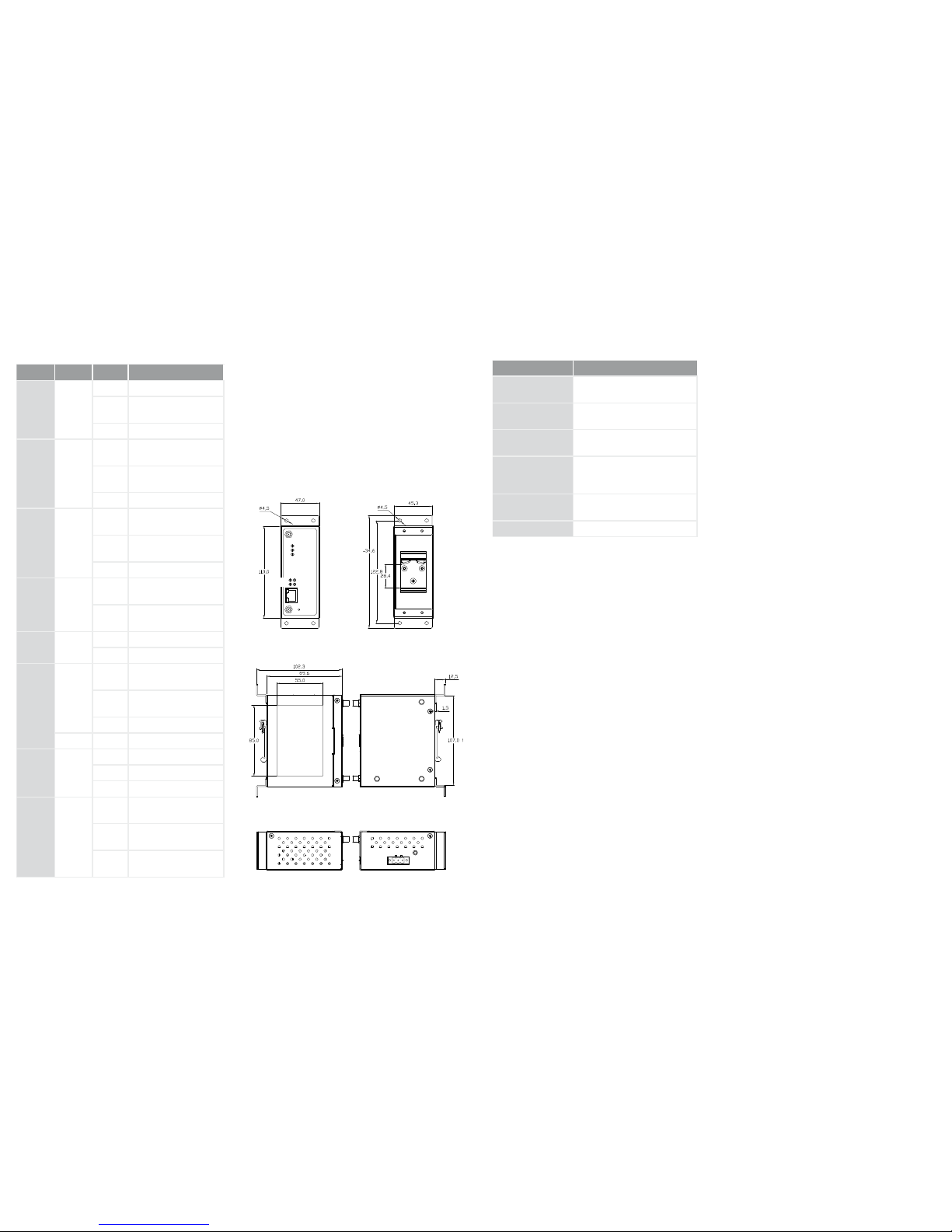
Dimensions / Mounting
Front
Left
Bottom
Right
Top
Back
• Proceed to mount the DM500 in a dry location free
from dirt and corrosive vapors, for more questions
on environmental limitations please refer to the
User’s manual.
• Unit Dimensions and Layout (unit=mm)
Optional Accessories
aRtICLe DeSCRIPtION
AD1024-24F
24 V DC 24 W
DIN-Rail Power Supply
6913DM500NT0
100 - 265 V AC to 12 V DC
Power Supply
MMO24580608NF
Rod Antenna, Omnidirectio-
nal, 2,4 / 5 GHz, 6 / 8 dBi
WMLPVIDB-
244958PTRPC
Low Profile Antenna, Omnidi-
rectional, 2,4 / 5 GHz,
4 / 4 dBi
MP24580809PTNF
Panel Antenna, directional,
2,4 / 5 GHz, 8 / 9 dBi
6913DM500WMK Aluminum Wallmount Kit
 Loading...