

Page 1
PHONE: (269)345.1132 • FAX: (269) 345-0095
W
ll
OPERATING & MAINTENANCE
INSTRUCTIONS
e
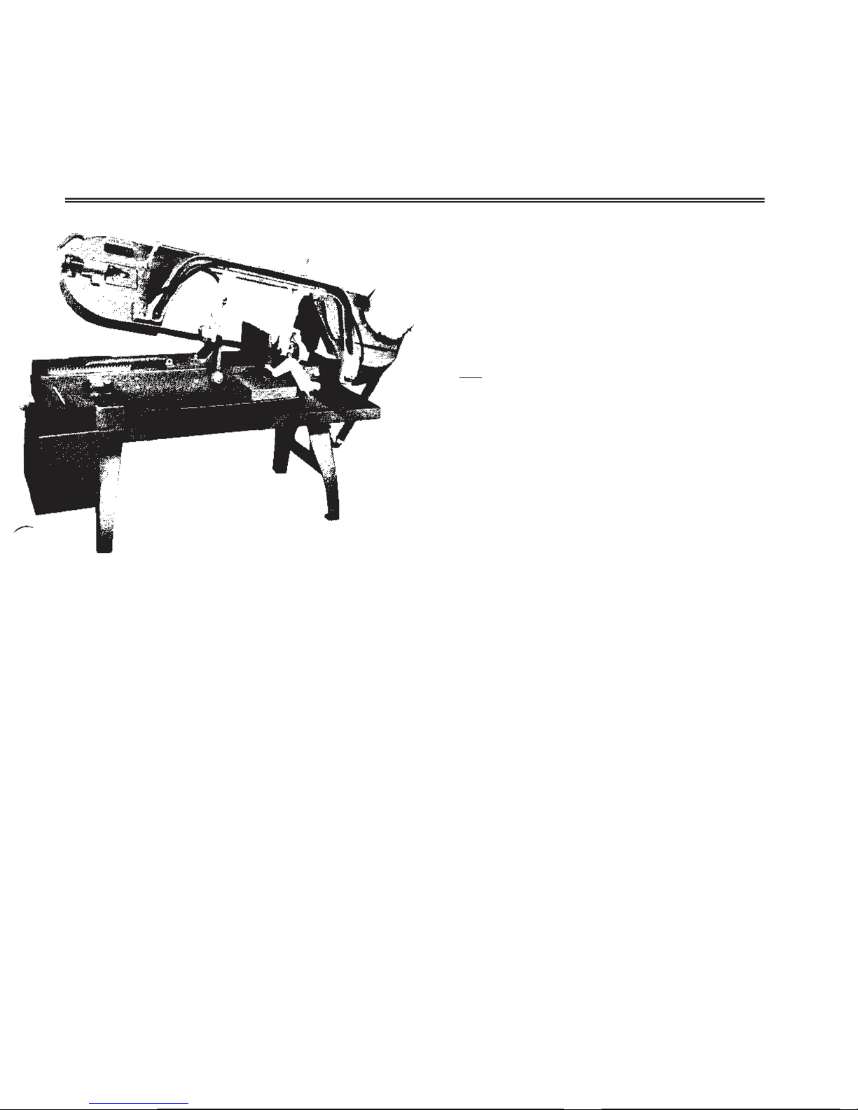
saw
MODEL 8
SPECIFICATIONS SEPTEMBER, 1971
Capacity:
Rectangular................................................... l6” (w) x 9" (h)
Rounds ....................................................................... 9" dia.
45 °Angle ........................................... 8-3/4" (w) x 9" (h)
With special guides .................................. 23" (w) x 9" (h)
or 24" (w) x
8" (h)
PLEASE READ THIS MANUAL CAREFULLY
IT WAS PREPARED TO HELP YOU
The Model 8 WELLS METAL CUTTING BAND
SAW was designed for efficient performance, and
with proper care will give you many years of dependable service.
After final assembly, each saw is inspected and
subjected to a test run; no adjustment should be
necessary.
This manual has been prepared to assist you in the
proper operation and maintenance of your new
WELLS Metal Cutting Band Saw. If you should desire
additional information or assistance, we suggest you
contact your dealer's service representative.
INSTALLATION
Upon receipt of machine, uncrate and check all
parts. Report to your carrier any damage to machine
and file Proof of Loss Claim with same.
Be sure motor specifications correspond with your power
line.
Place machine so that each leg is carrying its share of the
load.
Each machine is shipped with one all-purpose blade
installed and ready for use.
Selective
Motor.. .......................................................................... 1 H.P.
Drive. .......................................................................... "V" belt
Blade size ........................................... 11' 6" x 3/4" x .032"
Swivel vise ............................................................. to
Height to top of
Width of bed .......................................................... 10-1/4"
Floor space ............................................................... 24" x 72"
Approx. shipping weight ............................................ 590 lbs.
1. For longer blade life, start each cut carefully.
2. For new blades, reduce feeding pressure on first two
3. Keep blade guides as close to vise jaws as pos-
4. Make sure all four legs are in solid contact with
1. Raise fra me to extre me height.
2. Remove idle wh eel guard.
3. Remove blade guard on high side of frame.
4. Loosen blade take up screw and remove old
5. Uncoil new blade. Make certain that the blade
6. Place new blade between the bearings of the roller
blade speeds,
p rn 50, 100, 175, 275
f
450
bed .................................................. 25-1/2”
with wet
cutting system ....................................... 650 lbs.
SECTION I — OPERATING INSTRUCTIONS
CUTTING TIPS
cuts.
sible.
floor.
PLACING BLADE ON SAW
blade.
teeth point in direction of blade travel, which is
toward the motor. If not, turn the blade inside
out to have proper tooth direction.
guides and on band wheels.
Page 2

7. Grasp blade on frame side and push toward
guide bracket beam to hold it in position on
wheels while turning hand wheel tension screw
until blade is taut.
8. Start motor and tighten blade to proper operating
tension. If blade slips while cutting, increase the
tension.
AUTOMATIC STOP
When the saw blade has completed the cut through
the material, the saw frame drops on a trigger. This
operates a rod which opens the contacts in the
switch and automatically stops the motor.
It will be necessary to raise saw frame clear of the trigger
before machine can be started.
FIXED VISE JAW
The two pins in the fixed vise jaw should be kept
in place in order to insure square cuts. For cutting
angles, the pins must be removed and the vise jaws
turned to desired position and tightened with clamp
bolts. These pins enable operators to quickly relocate fixed vise jaw for approximate 90' cutting.
For final and accurate adjustment, the vise jaw
should be squared with the blade.
The sliding vise jaw should be loosened and pushed
against fixed vise jaw, then tighten cap screw , leaving
vise parallel.
SLIDING VISE JAW
The sliding vise jaw is equipped with a ratchet and
ratchet dog for quick action and with a hand wheel
for tightening work in vise. Excessive pressure is
not required to h old mat erial se cure.
MAXIMUM CAPACITY
To obtain maximum vise capacity, remove vise jaw
pins and move fixed vise jaw toward motor end to
the last holes. Make sure stock in vise will not
strike the ratchet arm.
DASH POT
Machines are equipped with a dash pot (frame check)
for the purpose of stabilizing the downward travel of
the saw frame, thereby protecting saw blade from
damage. The action is hydraulic and controlled by
flow of fluid being by-passed through an orifice in
the piston on the downward stroke.
Fill to within 1 inch of top of the bottom cylinder
with Mobil Velocite Oil # 6 or equivalent.
FRAME WEIGHT ADJUSTMENT
Before adjusting frame spring at motor end, remove
the hydraulic dash pot and move sliding weight to
rear position (motor end). The frame spring should
be adjusted for approximately 12 pounds weight at
frame handle.
SWITCH
A "STOP-START" switch is installed across the
line to protect wiring and the motor. A heater coil
breaks the circuit if an overload occurs. The operator should allow time for the coil to cool before
trying to restart.
Automatic shut-off operates when saw frame contacts the switch trigger.
BELT
Pivoted mounting provides quick belt change. With
the belt in pulley grooves for the desired speed,
swing motor to put proper tension on belt. Tighten
thumb screw to hold motor in operating position.
FEEDING PRESSURE
Variations in feeding pressure are made by moving
weight on bar at top side of frame. Pressure on blade
increases as weight is moved to forward end. The
size and type of material governs the amount of
feeding pressure required on the blade. Excessive
pressure may cause a run-out, of the blade.
SPEED SELECTION
Saws are equipped with step pulleys providing speed
selection of 50, 100, 175 and 275 feet per minute.
High speeds are suggested for cutting thin-wall
tubing, channels, aluminum, brass, or any metal that
will not burn the teeth; medium speed for general
cutting such as cold rolled, machine steels, heavy
channels, etc. Run in low speed for cutting nickel
steels, or metal which requires a slow speed an a
lathe. When cutting brass, use a blade which has not
previously cut other metal, and apply beeswax to the
teeth.
If teeth wear off unusually fast, use a lower speed.
BLADE BRUSHES
Brushes should be cleaned frequently in kerosene
and reversed to take advantage of both rows of
bristles
For efficient cutting and blade life, replace blade brushes
when worn.
In bolting brushes to angles, be sure wire bristles
are bent in the same direction the blade travels.
SECTION II — MAINTENANCE INSTRUCTIONS BLADE
GUIDES
The blade guides are arranged to hold the blade in
alignment both vertically and horizontally.
Page 3

Before making any adjustments, always try a new
blade to be sure that the old blade was not causing
the difficulty.
To align the blade horizontally, be sure fixed vise
is square with the slot in top of bed, then square
blade with vise.
For the vertical alignment, raise frame until blade
just clears bed, then place edge of square on bed
with end against blade, being careful not to contact
tooth set. Use feeler gauge not to exceed .002",
adjust blade so that feeler gauge will not enter at
top or bottom between end of square and blade at
both front and rear guides.
Adjust the side roller guides (100416-1) with the
eccentric axle until both rollers contact blade. When
this adjustment is made, the roller should be adjusted
so that the PATH of the BLADE IS STRAIGHT and
blade is not forced to curve around the rollers. The
top roller guide (100406-1) shou ld be in contact with
top edge of blade at all times. When running idle, this
contact pressure should be very light.
WHEEL PITCH ADJUSTMENT
LOOSEN BLADE BEFORE MAKING THESE
ADJUSTMENTS
!
then tighten two cap screws at opposite end of idler
wheel block. To reduce pitch on drive wheel, loosen
two cap screws in drive wheel plate at the end opposite the motor, then match pitch adjustment by tightening two hollow head set screws at the same end of
the wheel plate. The four cap screws should then be
tightened to hold motor plate in a rigid and fast
position.
LUBRICATION
Correct and adequate lubrication is a very important
factor in determining the life and service to be obtained. It is imperative that all dust and dirt be removed before lubricating.
Mobilgrease XHP 220, or equivalent, is used in the
gear case. Other parts to be greased are as follows:
1. Vise screw. Use anti-seize.
2. Use Extreme-Pressure Open Gear Lube on the
internal ring gear and drive pinion.
2. Wheel ball bearings are lubricated with a good
quality ball bearing grease.
3. Apply a few drops of machine oil to the frame pivot
bar periodically.
4. For proper motor lubrication, follow motor manu-
facturers instructions as stated on the motor.
If the blade runs too low or off the id ler wheel, adjust the idler wheel block. Loosen, by one-half turn,
the two cap screws in the block at the hand wheel
end, and tighten by an equal amount the two cap
screws in the opposite end of the block.
To make similar adjustment on drive wheel, loosen,
by one-half turn, the two cap screws at motor end of
the wheel plate. Then make pitch adjustment: loosen
by one-half turn, th e two hollow head set screws at
the opposite end of plate, and tighten the two hex
head cap screws at motor end of wheel plate. After
final adjustment, make certain that all hollow head
cap screws and set screws are tigh t.
If there is too much pitch on the wheel, the blade
will run too high. This will cause the blade to become distorted, the top edge will be rolled over and
the wheel rim flange will show excessive wear.
To correct this condition, loosen two cap screws at the
end of idler wheel block farthest from hand wheel,
HELPFUL SUGGESTIONS
1. To select the proper blade, consideration must
be given to the type of material, as well as size
and shape of stock to be cut. The WELLS-SELECT-O-CHART is a handy reference guide.
2. Use correct blade speed and pressure for each type
of material.
3. Always keep blade at proper tension.
4. Lower saw frame carefully so that the blade will
start cutting before full frame feed pressure is applied
to the blade.
5. Reduce feeding pressure for the first 2 or 3 cuts
with a new blade.
6. Keep adjustab le blade guide as close as possible to
the material.
7. Keep blade brushes in contact with blade teeth at all
times.
HOW TO ORDER REPAIR PARTS
Please provide following informatIon: Address order to:
Model Number WELSAW
Serial Number 2829 N. Burdick
Part Description and Number Kalamazoo, Michigan 49007, U.S.A.
in Parts List. Telephone: 269-345-1132 FAX: 269.345-0095
as shown
 Loading...