

Wells WVU-96 Owner’s Manual
Job Item No.
Over 90 Years Of Quality Foodservice
Products And Service
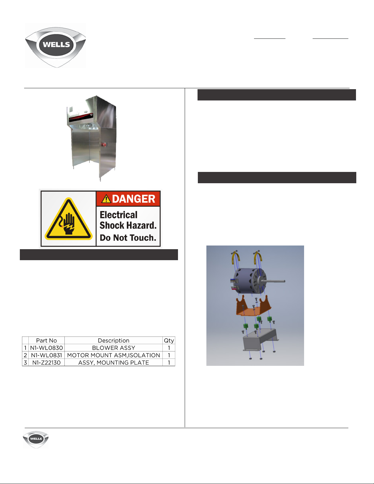
Motor Mount Kit Install WS-WL0848
WVU-48
WVU-96
UPDATE
Replacement pr
WVU96 v
details removing the blower motor mount, and
replacing it with a new blower motor mount. This
pertains to units before 08/01/2017.
ent-less h
CAUTION
Use proper safety measures when
performing this procedure. Ensure the unit is
disconnected from the electrical supply.
ocedure for the Wells WVU48 and
ood s
ystems. T
his P
rocedure
REMOVAL PROCEDURE
1. Check the parts kit (WSWL0848) to ensure all required
hardware is available.
2. Check that all the proper tools
required are available.
PARTS KIT #: WS-WL0848
WELLS MFG. 265 Hobson Street •
Smithville,Tennessee 37166 Telephone 888 356
5362 • Fax 314 781 5445 www.wells-mfg.com
Printed in the U.S.A. • 2M-Z22734 • REV - •
08.2018 Specifications are subject to change without
notice and are not intended for installation purposes.
Over 90 Years Of Quality Foodservice
Products And Service
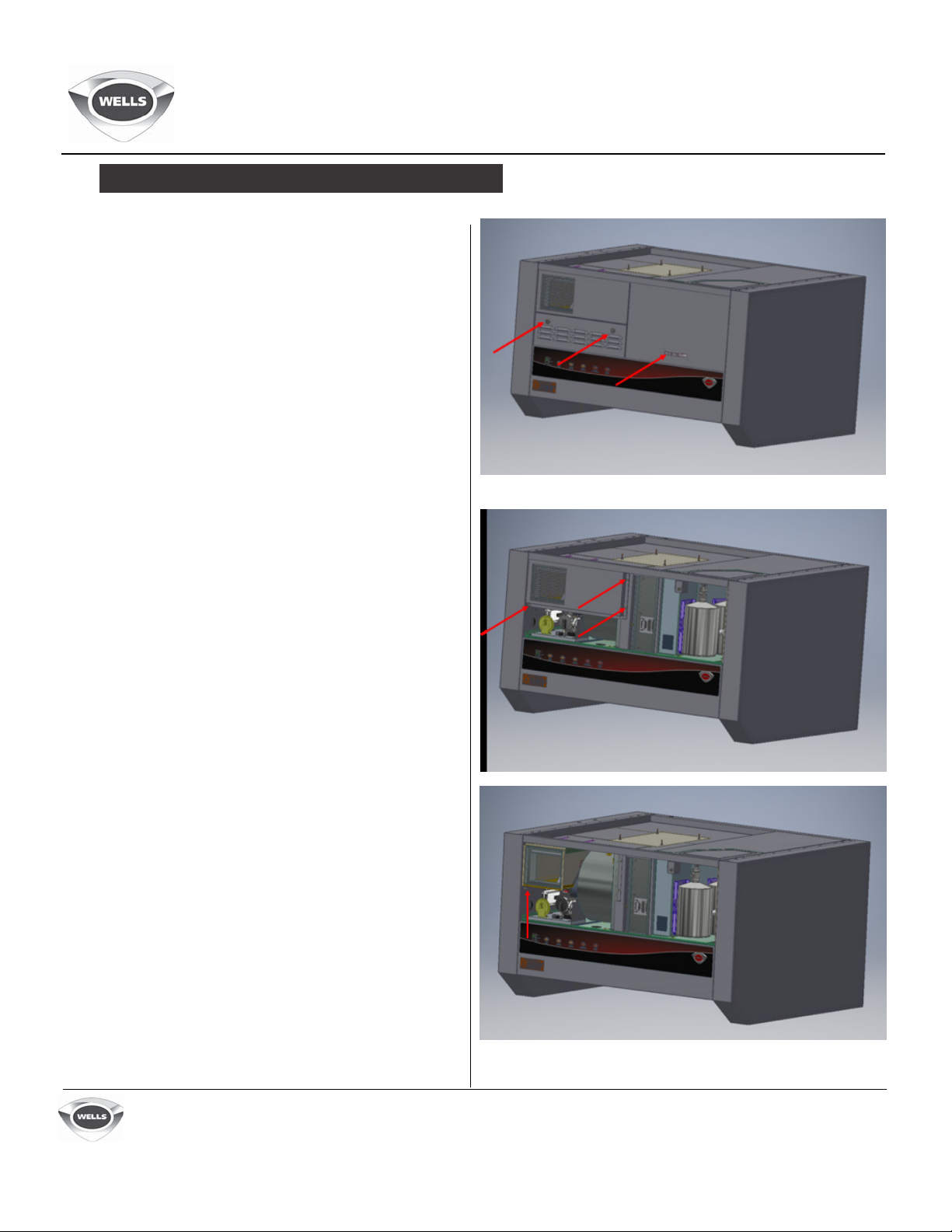
REMOVAL PROCEDURE (CONTINUED)
3. Remove the filter door.
4. Unlock the electrical access
door assembly and remove it.
WVU48-WVU96
Motor Mount Kit Install
WS-WL0848
5. Remove the screws (3) on the
front discharge panel. Save the
hardware for reassembly.
6. Remove the front duct screw from
the damper duct and slide the duct
out the front. Save the hardware for
reassembly.
WELLS MFG. 265 Hobson Street •
Smithville,Tennessee 37166 Telephone 888 356
5362 • Fax 314 781 5445 www.wells-mfg.com
Printed in the U.S.A. • 2M-Z22734 • REV - •
08.2018 Specifications are subject to change without
notice and are not intended for installation purposes.
MADE IN THE
Over 90 Years Of Quality Foodservice
Products And Service
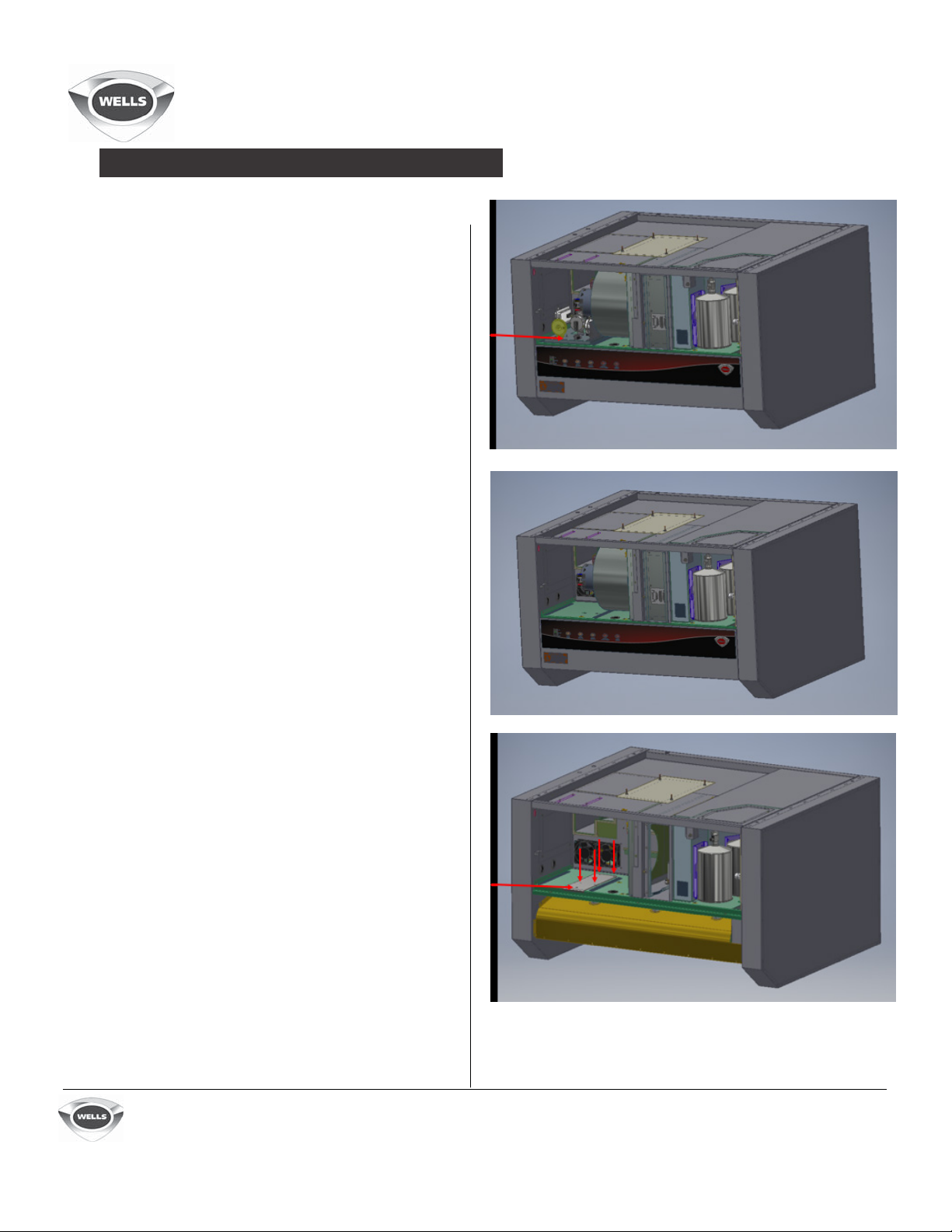
REMOVAL PROCEDURE (CONTINUED)
7. Remove the retaining screw on the
internal control panel assembly and
slide it partially out to access the
electrical connections and vacuum
hoses.
8. Remove the nuts on the vacuum
switches, timer, and buzzer so the
panel is able to be removed. Discard
the old panel.
9. Place the sensors and vacuum
pumps off to the sides.
10. Remove the HEPA filter and set
aside for later use.
11.Disconnect the motor power wiring.
12. Remove the bolts from the
blower assembly and slide the blower
out the front of the unit. Retain the
bolt hardware for reassembly.
13. Remove the front panel assembly
and place the drill fixture over the
weld screw head. Center mark the
mounting screws (4) and clearance
them to 1/4-20 screw (0.257).
14. Drill the holes, be careful to not
drill into the wiring or curved deck.
WELLS MFG. 265 Hobson Street •
Smithville,Tennessee 37166 Telephone 888 356
5362 • Fax 314 781 5445 www.wells-mfg.com
Printed in the U.S.A. • 2M-Z22734 • REV - •
08.2018 Specifications are subject to change without
notice and are not intended for installation purposes.
 Loading...