

Wells WVU-31CT Installation Manual
WELLS MANUFACTURING
10 Sunnen Dr., St. Louis, MO 63143
telephone: 314-678-6314
fax: 314-781-2714
www.wellsbloomfield.com
OWNERS MANUAL
COUNTERTOP
VENTLESS UNIVERSAL
HOOD SYSTEM
COUNTERTOP ELECTRIC
APPLIANCES
524
for
MODEL
WVU-31CT
Manual Includes
INSTALLATION
USE & CARE
EXPLODED VIEW
PARTS LIST
IL2732
IMPORTANT: DO NOT DISCARD THIS MANUAL
This manual is considered to be part of the appliance and is to be given to the OWNER or
MANAGER of the restaurant, or to the person responsible for TRAINING OPERATORS of
this appliance. Additional manuals are available from your WELLS DEALER.
WIRING DIAGRAM
THIS MANUAL MUST BE READ AND UNDERSTOOD BY ALL PERSONS USING OR
INSTALLING THIS APPLIANCE. Contact your WELLS DEALER if you have any
questions concerning installation, operation or maintenance of this equipment.
p/n 2M-Z17951, Rev. B M524 150102

LIMITED WARRANTY STATEMENT
Unless otherwise specied, all commercial cooking
equipment manufactured by Wells Manufacturing is
warranted against defects in materials and workmanship
for a period of one year from the date of original installation
or 18 months from the date of shipment from our factory,
whichever comes rst, and is for the benet of the original
purchaser only.
THIS WARRANTY IS THE COMPLETE AND ONLY
WARRANTY, EXPRESSED OR IMPLIED IN LAW
OR IN FACT, INCLUDING BUT NOT LIMITED TO,
WARRANTIES OF MERCHANTABILITY OR FITNESS FOR
ANY PARTICULAR PURPOSE, AND/OR FOR DIRECT,
INDIRECT OR CONSEQUENTIAL DAMAGES IN
CONNECTION WITH WELLS BLOOMFIELD PRODUCTS.
This warranty is void if it is determined that, upon inspection
by an authorized service agency, the equipment has been
modied, misused, misapplied, improperly installed, or
damaged in transit or by re, ood or act of God. It also does
not apply if the serial nameplate has been removed, or if
service is performed by unauthorized personnel. The prices
charged by Wells Manufacturing for its products are based
upon the limitations in this warranty. Seller’s obligation
under this warranty is limited to the repair of defects without
charge by a Wells Manufacturing factory authorized service
agency or one of its sub-service agencies. This service
will be provided on customer’s premises for non-portable
models. Portable models (a device with a cord and plug)
must be taken or shipped to the closest authorized service
agency, transportation charges prepaid, for service. In
addition to restrictions contained in this warranty, specic
limitations are shown in the Service Policy and Procedure
Guide. Wells Manufacturing authorized service agencies
are located in principal cities. This warranty is valid in the
United States and Canada and void elsewhere. Please
consult your classied telephone directory, your foodservice
equipment dealer or contact:
Wells Manufacturing
10 Sunnen Dr., St. Louis MO 63143 USA
phone (314) 678-6314 or fax (314) 781-2714
for information and other details concerning warranty.
SERVICE POLICY AND PROCEDURE GUIDE and ADDITIONAL WARRANTY EXCLUSIONS
1. Resetting of safety thermostats, circuit breakers, over
load protectors, and/or fuse replacements are not
covered by this warranty unless warranted conditions
are the cause.
2. All problems due to operation at voltages or phase
other than specied on equipment nameplates are
not covered by this warranty.
Conversion to correct voltage and/or phase must be
the customer’s responsibility.
3. All problems due to electrical connections not made
in accordance with electrical code requirements
and wiring diagrams supplied with the equipment are
not covered by this warranty.
4. Replacement of items subject to normal wear, to
include such items as knobs, light bulbs; and, normal
maintenance functions including adjustments of
thermostats, adjustment of micro switches and
replacement of fuses and indicating lights are not
covered by warranty.
5. Damage to electrical cords and/or plug due to exposure
to excessive heat are not covered by this warranty.
6. Full use, care, and maintenance instructions supplied
with each machine. Noted maintenance and
preventative maintenance items, such as servicing and
cleaning schedules, are customer responsibility. Those
miscellaneous adjustments noted are customer
responsibility. Proper attention to preventative
maintenance and scheduled maintenance procedures
will prolong the life of the appliance.
7. Travel mileage is limited to sixty (60) miles from an
Authorized Service Agency or one of its sub-service
agencies.
8. All labor shall be performed during regular working
hours. Overtime premium will be charged to the buyer.
9. All genuine Wells replacement parts are warranted
for ninety (90) days from date of purchase on non-
warranty equipment. This parts warranty is limited only
to replacement of the defective part(s). Any use of
non-genuine Wells parts completely voids any
warranty.
10. Installation, labor, and job check-outs are not
considered warranty and are thus not covered by this
warranty.
11. Charges incurred by delays, waiting time or operating
restrictions that hinder the service technician’s ability to
perform service are not covered by warranty. This
includes institutional and correctional facilities.
SHIPPING DAMAGE CLAIM PROCEDURE
NOTE: For your protection, please note that equipment
in this shipment was carefully inspected and packaged
by skilled personnel before leaving the factory. Upon
acceptance of this shipment, the transportation company
assumes full responsibility for its safe delivery.
IF SHIPMENT ARRIVES DAMAGED:
1. VISIBLE LOSS OR DAMAGE: Be certain that any
visible loss or damage is noted on the freight bill or
express receipt, and that the note of loss or damage is
signed by the delivery person.
2. FILE CLAIM FOR DAMAGE IMMEDIATELY:
Regardless of the extent of the damage.
3. CONCEALED LOSS OR DAMAGE: if damage is
unnoticed until the merchandise is unpacked, notify the
transportation company or carrier immediately, and le
“CONCEALED DAMAGE” claim with them. This
should be done within fteen (15) days from the date
the delivery was made to you. Be sure to retain the
container for inspection.
Wells Manufacturing cannot assume liability for damage or
loss incurred in transit. We will, however, at your request,
supply you with the necessary documents to support your
claim.
xi
TABLE OF CONTENTS
WARRANTY xi
ELECTRICAL SPECIFICATIONS 1
WARNINGS - ENGLISH 2
WARNINGS - FRENCH 3
CLEARANCES 4
FIRE SUPPRESSION SYSTEM 5
FEATURES & OPERATING CONTROLS 6-7
PRECAUTIONS & GENERAL INFORMATION 8
AGENCY LISTING INFORMATION 9
INSTALLATION 9
Unpacking & Inspection 9
Components 9
Under-Hood Appliance Limitations 10
Service Technician Installation Notes 11
Site Preparation 12
Mechanical Installation 13
Electrical Installation 14-15
ANSUL® INSTALLATION & SETUP 14-15
Fire Suppression System Installation 16
Filter Installation 17
OPERATION 18
Control Panel 18
Operation Lights 18
CLEANING INSTRUCTIONS 19-20
REQUIRED MAINTENANCE & MAINTENANCE LOGS 21-25
TROUBLESHOOTING SUGGESTIONS 26
WIRING DIAGRAM 27
EXPLODED VIEW & PARTS LIST 28-33
INTRODUCTION
Thank You for purchasing this Wells Manufacturing appliance.
Proper installation, professional operation and consistent maintenance of this appliance will ensure
that it gives you the very best performance and a long, economical service life.
This manual contains information and instructions for the ventless ventilation hood, its use and care.
For information regarding cooking appliance(s), please refer to the manufacturer’s operation manual.
ELECTRICAL SPECIFICATIONS
Model Volts Amps Power Supply
WVU-31CT 208/240V 1.9 For supply connection use #12 AWG copper wire only.
M524 p/n 2M-Z17951 OpM WVU- Countertop Universal Hood
1
WARNINGS - ENGLISH
IMPORTANT: DO NOT DISCARD THIS MANUAL
This manual is considered to be part of the appliance and is to be given to the OWNER or
MANAGER of the restaurant, or to the person responsible for TRAINING OPERATORS of this
appliance. Additional manuals are available from your WELLS DEALER.
THIS MANUAL MUST BE READ AND UNDERSTOOD BY ALL PERSONS USING OR INSTALLING THIS
APPLIANCE. Contact your WELLS DEALER if you have any questions concerning installation, operation
or maintenance of this equipment.
DANGER
FIRE HAZARD
Fire suppression system must be charged and
certied by an authorized Ansul® distributor.
DO NOT attempt to modify or bypass the re
suppression system.
An uncontrolled re can cause serious injury or
death.
WARNING:
If the re suppression system is
discharged, a buzzer will sound
continuously. The unit will remain
inoperable until the re suppression system
is serviced, recharged and reset by an
authorized Ansul® distributor.
NOTE:
If a REMOTE MANUAL PULL STATION
is installed, moving the ventilator for any
reason may cause the Ansul® system to
discharge.
DANGER - DO NOT BLOCK ACCESS
TO THE FIRE EXTINGUSHING
MANUAL PULL.
DANGER:
SUFFOCATION HAZARD
“Do not attempt to use this ventilator with
gas-red units. This ventilator will not
remove products of combustion. Unvented
exhaust gasses can be deadly.”
WARNING:
SHOCK HAZARD
All servicing requiring access to non-insulated
electrical components must be performed by
a factory authorized technician.
DO NOT open any access panel which
requires the use of tools. Failure to follow this
warning can result in severe electrical shock.
WARNING:
RISK OF INJURY
Installation procedures must be performed by
a qualied technician with full knowledge of all
applicable electrical codes. Failure can result
in personal injury and property damage.
WARNING:
SLIP AND FALL HAZARD
DO NOT operate any grease-producing
cooking appliance unless the grease cup
is properly installed. Oil will drip onto oor
creating a slipping hazard.
WARNING:
DO NOT attempt to wash the HEPA /
CHARCOAL lter pack or pre-lter. Water
absorption will render the lter unusable.
Use of a wet or clogged lter will cause the
ventilator system to shut down. Use only
new, clean Wells® Authorized Service Parts.
Keep spare lter packs on hand to avoid
distrupions. Service Department 1-314-678-
6314.
Exposed surfaces can be hot to the touch and
may cause burns. Allow unit to cool before
cleaning or servicing.
M524 p/n 2M-Z17951 OpM WVU- Countertop Universal Hood
2
WARNINGS - FRENCH
IMPORTANT : NE JETEZ PAS CE MANUEL
Ce manuel fait partie intégrante de l’appareil et doit être remis au PROPRIÉTAIRE, au GÉRANT
du restaurant ou au responsable de la FORMATION DES UTILISATEURS. Des manuels
supplémentaires sont disponibles auprès de votre concessionnaire WELLS.
TOUTE PERSONNE INSTALLANT OU UTILISANT CET APPAREIL DOIT LIRE CE MANUEL ET
S’ASSURER DE L’AVOIR COMPRIS.
Veuillez contacter votre CONCESSIONNAIRE WELLS pour toute question concernant
l’installation, l’utilisation ou l’entretien de cet équipement.
DANGER
RISQUE D’INCENDIE
Le système anti-incendie doit être chargé
et certié par un distributeur agréé Ansul®.
N’essayez PAS de modier ou de
contourner le système anti-incendie.
Un feu hors de contrôle risque de
provoquer des blessures graves, voire
mortelles.
AVERTISSEMENT :
Une alarme sonore se déclenche en
continu si le système anti-incendie est
déchargé. L’unité reste inutilisable
jusqu’à ce qu’un distributeur agréé Ansul®
effectue son intervention, le recharge et le
réinitialise.
REMARQUE :
Si un AVERTISSEUR D’INCENDIE À
DISTANCE MANUEL est installé, tout
déplacement du ventilateur, quel qu’en soit
le motif, peut provoquer la décharge du
système Ansul®.
DANGER - NE PAS BLOQUER
L’ACCÈS À LA POIGNÉE DE
L’EXTINCTEUR !
DANGER :
RISQUE DE SUFFOCATION
“Ce ventilateur ne doit pas être utilisé avec
des appareils à gaz. Il n’absorbe pas les
produits de combustion. En l’absence de
sortie d’aération, les gaz de combustion
peuvent être mortels.”
AVERTISSEMENT :
RISQUE DE DÉCHARGE ÉLECTRIQUE
Toute intervention nécessitant d’accéder à des
composants électriques non isolés doit être
effectuée par un technicien agréé usine.
N’ouvrez AUCUN panneau d’accès nécessitant
l’utilisation d’un outil. Le non-respect de cet
avertissement peut exposer à une décharge
électrique sévère.
AVERTISSEMENT :
RISQUE DE BLESSURE
Les procédures d’installation doivent être
effectuées par un technicien qualié ayant pleine
connaissance des réglementations applicables. Le
non-respect de cet avertissement peut provoquer
des blessures et des dommages matériels.
AVERTISSEMENT :
RISQUE DE CHUTE
N’utilisez PAS d’appareil de cuisson produisant
de la graisse sans que le godet à graisse soit
correctement installé. Vous risqueriez de glisser
car la graisse éclabousserait le sol.
AVERTISSEMENT :
N’essayez PAS de nettoyer le ltre ou le pré-ltre
HEPA ou à CHARBON. L’eau absorbée rendrait
le ltre inutilisable. Un ltre humide ou colmaté
provoque l’arrêt du système de ventilation. Utilisez
uniquement des pièces neuves et propres,
homologuées par Wells®. Conservez des
ltres de rechange pour éviter l’interruption du
fonctionnement.
Service clientèle : +1-314-678-6314.
M524 p/n 2M-Z17951 OpM WVU- Countertop Universal Hood
3
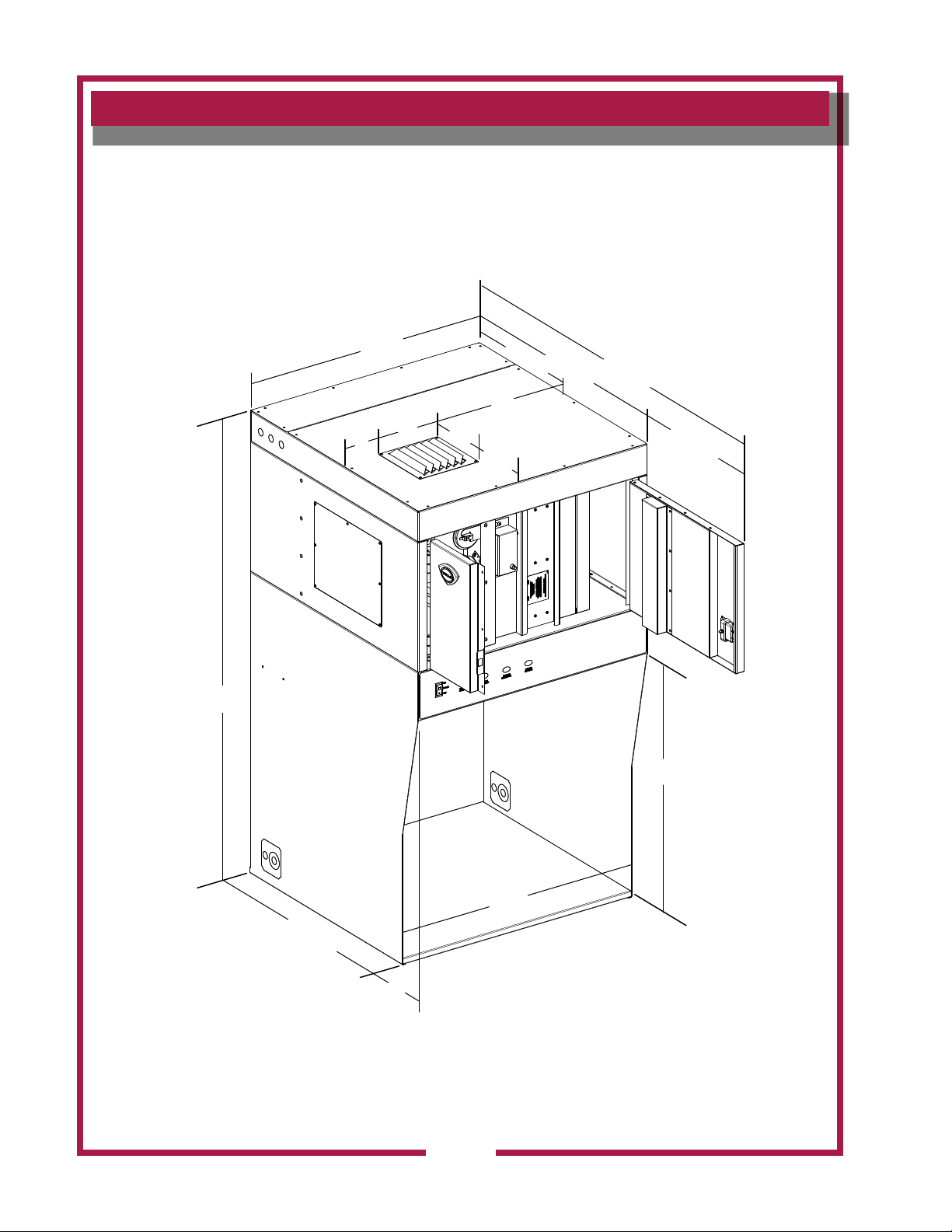
CLEARANCES
56.7”
31.1”
5”
8”
8”
18”
4.8”
19.72”
32.52”
53.30”
20.78”
30.2”
29.5”
31”
3”
IL2734
M524 p/n 2M-Z17951 OpM WVU- Countertop Universal Hood
4
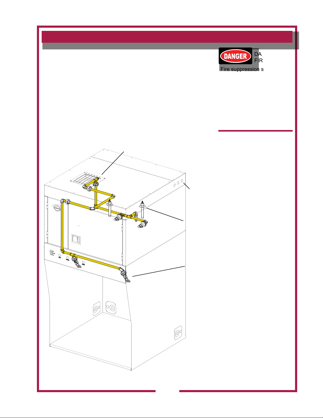
FIRE SUPPRESSION SYSTEM
CUSTOMER
Fire Suppression System Installation
It is required that this unit be protected by a UL listed re suppression
system, provided by the customer. The nal installation, testing and
certication of the system is the responsibility of the customer and MUST
be performed by a qualied Fire Protection Agent in accordance with the
hood system.
This Wells Ventless System includes factory installed piping, plenum,
discharge nozzles, thermal detectors.
ANSUL HOOK-UP
ELECTRIC & ANSUL
KNOCK-OUTS
(3 SIDES)
THERMAL
DETECTORS
(2 PLACES)
NOZZELS
(5 TOTAL)
DANGER
FIRE HAZARD
Fire suppression system
must be charged and certied
by an authorized Ansul®
distributor.
DO NOT attempt to modify or
bypass the re suppression
system.
An uncontrolled re can
cause serious injury or death.
NOTE:
If the re suppression system
is discharged, a buzzer will
sound continuously. The unit
will remain inoperable until
the re suppression system is
serviced, recharged and reset
by an authorized Ansul®
distributor.
Charging of the Ansul®
Fire Suppression system
must be in accordance with
Ansul® Design, Installation,
Recharge and Maintenance
Manual, #418087.
NOTE:
If a REMOTE MANUAL PULL
STATION is installed, moving
the ventilator for any reason
may cause the Ansul®
system to discharge.
M524 p/n 2M-Z17951 OpM WVU- Countertop Universal Hood
IMPORTANT:
Should the re suppression
system discharge: all nozzles
must be replaced, and all
lines thoroughly cleaned,
prior to recharging the
system.
Residual re suppression
media may compromise the
ow and dispersion of re
IL2740
suppression media in any
subsequent activation.
5
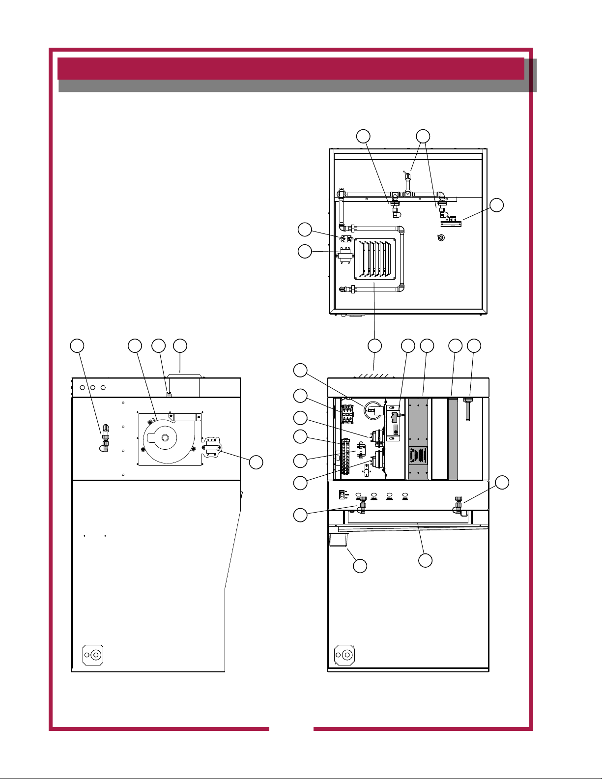
FEATURES & OPERATING CONTROLS
11
5
3
17
4
3
21
84
765
9
10
11
12
18
19
13
1
1
14
15
Countertop Ventilator Section Operating Features & Controls
6
IL2735
M524 p/n 2M-Z17951 OpM WVU- Countertop Universal Hood
FEATURES & OPERATING CONTROLS continued
FEATURES & OPERATION CONTROLS
ITEM NO DESCRIPTION COMMENT
1 DISCHARGE NOZZLES Fire suppression media discharges here, (5 places)
2 VENTILATOR FAN Provides air movement for ventilation
3 DETECTION END OF LINE RELAY Prevents appliance operation if a fault is found in detection circuit.
4 VENTILATOR EXHAUST DUCT, FRONT Exit point for ventilator airow - on front of unit. DO NOT BLOCK
5 FILTER INTERLOCK SWITCHES
6 HI-EFFICIENCY/CHARCOAL FILTER PACK
7 PRE-FILTER
8 ELECTRICAL DETECTORS
9 PRE-FILTER SWITCH
10 EQUIPMENT INTERFACE CONTACTOR
11 HEPA FILTER SWITCH
12 SUPPLY CONNECTION TERMINAL BLOCK Provides connection point for electrical circuitry
13 UNIT SHUT-DOWN SWITCH
14 GREASE DRIP TRAY Collects grease/moisture dripping from bafe lter (16)
15 BAFFLE FILTER Extracts and drains most greases and moisture from the air ow.
16 APPLIANCE LIGHT (Not Shown) ON when hood power switch is ON. Illuminates cooking area.
17 120V TRANSFORMER Provides power to appliance lights
18 120V TRANSFORMER Provides power to contactor relay
19 BUILDING ALARM RELAY Provides electrical connections for building alarm system
Proper installation of bafe lter and lter pack closes these switches
in ventilator sensor circuit
Removes grease and smoke particles. Also assists in cooking odor
removal.
Replaceable PRE-FILTER, stops large particles of grease from
reaching the FILTER PACK for reduced maintenance costs.
Designed to activate at a certain temperature. Activates (i.e. re on
the cooktop) activates re suppression system. Should be checked
every 6 months during ANSUL® Service Inspection
Monititors the Pre-Filter and indicates when it needs replacing, if
ignored it will lead to unit shut down.
Energizes cooking appliances only while ventilator section is sensed
as operational.
Montitors the HEPA lter and indicates when it needs replacing, if
ignored it will lead to unit shut down.
Shuts down the unit and appliances when the lack of air ow reaches
a certain level, triggers a service unit indicator.
M524 p/n 2M-Z17951 OpM WVU- Countertop Universal Hood
7
PRECAUTIONS AND GENERAL INFORMATION
This ventilator hood is part of an engineered system and is intended for
use in commercial establishments only.
This ventilator is intended
DANGER:
SUFFOCATION HAZARD
Do not attempt to use this
ventilator with gas-red units.
This ventilator will not remove
products of combustion.
Unvented exhaust gasses
can be deadly.
WARNING:
SHOCK HAZARD
All servicing requiring
access to non-insulated
electrical components must
be performed by a factory
authorized technician.
DO NOT open any access
panel which requires the use
of tools. Failure to follow this
warning can result in severe
electrical shock.
IMPORTANT:
The ventilator is disabled
when the lters are plugged
to the point of insufcient
airow for proper operation.
Also, power to the cooking
appliances is interrupted if
any lters or service panel
are removed.
It is the responsibility of
the store management to
maintain sufcient spares
of lter packs to avoid
prolonged shutdown due
to a dirty or clogged lter
pack. Filter packs cannot be
cleaned.
Wells Manufacturing
assumes no liability for loss
of business due to a lter
related shutdown. Spare
lters can be purchased
from any authorized Wells
servicer or calling Wells.
in the preparation food for human consumption. No other use is
recommended or authorized by the manufacturer or its agents.
Operators of this appliance must be familiar with the appliance use,
limitations and associated restrictions. Operating instructions must be
read and understood by all persons using or installing this appliance.
This ventilator hood system is designed to reduce odor emissions,
but will not completely eliminate all cooking odors. Air exchange
rates at the installation site must comply with the requirements of the
local jurisdictional authority. To ensure that odors do not accumulate,
recommended minimum air exchange is 200 cfm per linear foot of hood
into and out of the site.
This unit is intended for use with light- and medium duty electric
cooking appliances only. Cooking appliances placed under this
ventilator must comply with the restrictions set forth in the Installation
section of this manual.
Do not connect or energize this appliance until all installation
instructions are read and understood. Property damage or bodily
injury may result if these instructions are not followed. Disconnect this
appliance from electrical power before performing any maintenance or
servicing.
Cleanliness of this appliance is essential to good sanitation. Read and
follow all included cleaning instructions and schedules to ensure the
safety of the food product.
This appliance is not jet steam approved. Do not direct water jet or
steam jet at this appliance, or at any control panel or wiring.
Do not splash or pour water on, in or over any controls, control panel or
wiring. Do not attempt to wash lter packs. Water will cause their
immediate failure and disable the ventilator.
Exposed surfaces of this appliance can be hot to the touch and may
cause burns.
Avoid storing ammable or combustible materials in, on or near the
ventilator or associated cooking appliance.
The technical content of this manual, including any wiring diagrams,
schematics, parts breakdown illustrations and/or adjustment
procedures, is intended for use by qualied technical personnel.
Any procedure which requires the use of tools must be performed by a
qualied technician.
All supplied instructions, diagrams, schematics, parts breakdown
illustrations, notices and labels must remain with the appliance if the
unit is sold or moved to another location.
This appliance is made in the USA. Unless otherwise noted, this
appliance has American sizes on all hardware.
for commercial establishments for use
M524 p/n 2M-Z17951 OpM WVU- Countertop Universal Hood
8
AGENCY LISTING INFORMATION
This appliance conforms to NSF Standard 2 for sanitation only if
installed in accordance with the supplied Installation Instructions
and operated and maintained in accordance with the instructions in this
manual.
This appliance is ETL listed.
STD 2
UL710B
Recurculating System
INSTALLATION
UNPACKING & INSPECTION
Carefully remove the appliance from the carton. Remove all
protective plastic lm, packing materials and accessories from the
appliance before connecting electrical power or otherwise performing
any installation procedure.
Carefully read all instructions in this manual and any other docments
packed with the appliance before starting any installation.
All documentation should remain with the equipment operator for future
reference.
Read and understand all labels and diagrams attached to the
ventilator.
Carefully account for all components and accessories before
discarding packing materials.
COMPONENTS
Pre-Filter 1 ea.
Bafe Filter 1 ea.
Filter pack 1 ea.
Grease cup 1 ea.
Ansul® components - must be supplied by customer and installed
by an authorized Ansul® distributor only:
The unit is shipped with an angled discharge grill.
To change the direction of the discharge airow:
1. Remove the discharge grill by removing the four (4) mounting
screws on the grill.
2. Rotate the discharge grill to the desired discharge position.
3. Re-Secure the grill using the four (4) mounting screws.
NOTE: DO NOT discard
the carton or other packing
materials until you have
inspected the appliance for
hidden damage and tested it
for proper operation.
Refer to SHIPPING DAMAGE
CLAIM PROCEDURE on the
inside front cover of this
manual.
WARNING:
Risk of injury
Installation procedures must
be performed by a qualied
technician with full knowledge
of all applicable electrical
codes. Failure can result in
personal injury and property
damage.
IMPORTANT:
Fire suppression system must
be charged and certied by an
authorized Ansul® distributor.
Ventilator will not operate and
cooking appliance will not be
energized until the Ansul® re
suppression system has been
charged.
IMPORTANT:
After cooking appliances
are positioned under the
hood, swivel nozzles must
be positioned per Ansul®
recommendations.
M524 p/n 2M-Z17951 OpM WVU- Countertop Universal Hood
9
INSTALLATION (continued)
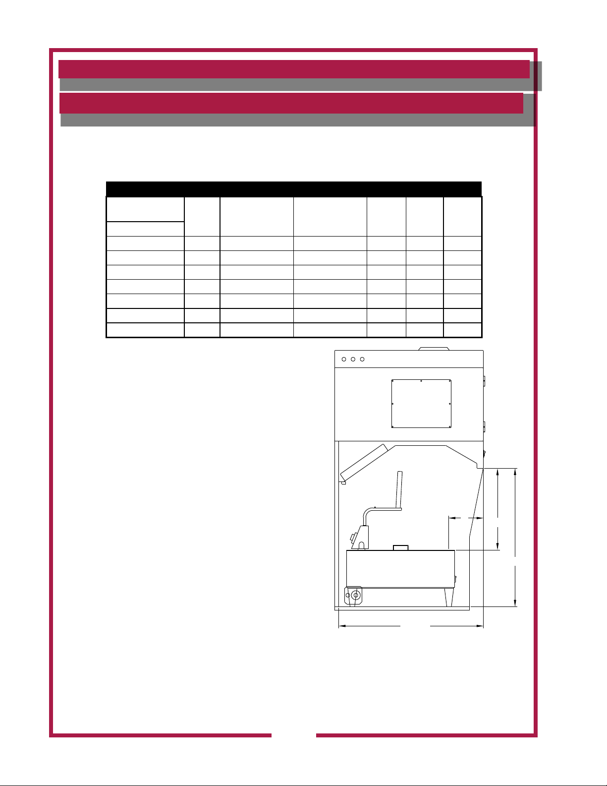
UNDER-HOOD APPLIANCE LIMITATIONS:
Appliance must be installed per manufactures instructions.
1.
2. Electrical appliances only. Not Intended for gas red units.
3. All appliances under the hood must be connected to the hood appliance interlock circuit.
4. All appliances must meet the requirements outlined in the cooking appliance limitations chart below.
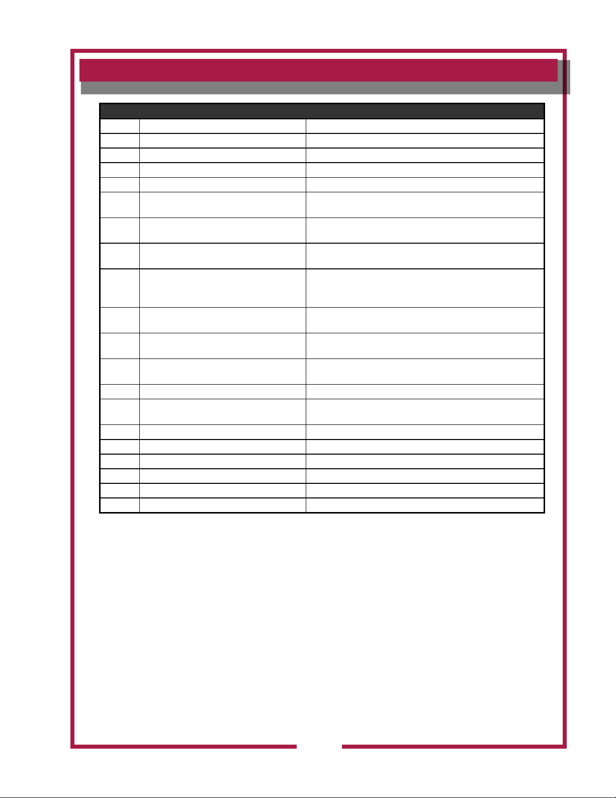
EQUIPMENT PARAMETER WVU-31CT
Coverage Parameters
Appliance Type
Fryer 16.9 400°F (204°C) 24 5 12 20
Griddle 5.5 450°F (232°C) 24 5 12 20
Hotplate 5.5 N/A N/A 5 15 25
Counter Top Oven N/A 550°F (287°C) 27 4 5 N/A
Sandwich Grills 5.5 450°F (232°C) 24 5 10 25
Convection Oven N/A 550°F (287°C) 27 5 5 N/A
Micro Combi Oven N/A 550°F (287°C) 27 4 5 N/A
(A) FRONT OF HOOD TO FRONT EDGE OF HEATED
COOKING SURFACE.
(B) BOTTOM FRONT EDGE OF HOOD TO HEIGHT OF
HEATED COOKING SURACE.
Maximum
kW / Ft
Maximum Cooking
Temperature
Maximum Single
Appliance Heated
Cooking Surface
The hood and all under hood appliances must be installed
in accordance with the standard for ventilation control and
re protection of commercial cooking operations NFPA
96, the national electric code NFPA 70 and all local codes
where applicable.
All under hood appliances must be controlled by the
equipment shutoff interface. Only electrically heated
appliances are acceptable for installation. Appliance
operation requires the re suppression system be setup,
charged and certied by an authorized ansul ® distributor.
The airow monitoring system will prevent appliance
operation if insufcient airow is detected or all lters are
not in place. The service panel must be in place for blower
operation.
Dim A,
Minimum
(A)
Dim B,
Minimum
(B)
Dim B,
Maximum
(B)
A
B
30.24
WELLS MANUFACTURING
MODEL NO: WVU-31CT
LOWER AIR FLOW LIMIT: 375CFM
MAXIMUM MEASURED GREASE EMISSIONS: .000693 LB/HR/FT
ANSI-UL710B RECIRCULATING SYSTEM
10
31.63
SIDE VIEW
M524 p/n 2M-Z17951 OpM WVU- Countertop Universal Hood
 Loading...