

Page 1
WELLS MANUFACTURING
10 Sunnen Dr., St. Louis, MO 63143
telephone: 314-678-6314
fax: 314-781-2714
www.wellsbloomfield.com
OWNERS MANUAL
VENTLESS UNIVERSAL
MODULAR HOOD SYSTEM
ELECTRIC
COOKING
APPLIANCES
521
for
Model WVU-1
MODEL
WVU-1
WVU-1P
Manual Includes
INSTALLATION
USE & CARE
EXPLODED VIEW
PARTS LIST
WIRING DIAGRAM
IMPORTANT: DO NOT DISCARD THIS MANUAL
This manual is considered to be part of the appliance and is to be given to the OWNER or
MANAGER of the restaurant, or to the person responsible for TRAINING OPERATORS of
this appliance. Additional manuals are available from your WELLS DEALER.
THIS MANUAL MUST BE READ AND UNDERSTOOD BY ALL PERSONS USING OR
INSTALLING THIS APPLIANCE. Contact your WELLS DEALER if you have any
questions concerning installation, operation or maintenance of this equipment.
p/n 2M-Z17085 Rev. (C) M521 130521
Page 2

LIMITED WARRANTY STATEMENT
Unless otherwise specied, all commercial cooking equipment
manufactured by Wells Manufacturing is warranted against
defects in materials and workmanship for a period of one year
from the date of original installation or 18 months from the
date of shipment from our factory, whichever comes rst, and
is for the benet of the original purchaser only.
THIS WARRANTY IS THE COMPLETE AND ONLY
WARRANTY, EXPRESSED OR IMPLIED IN LAW OR IN
FACT, INCLUDING BUT NOT LIMITED TO, WARRANTIES
OF MERCHANTABILITY OR FITNESS FOR ANY
PARTICULAR PURPOSE, AND/OR FOR DIRECT, INDIRECT
OR CONSEQUENTIAL DAMAGES IN CONNECTION
WITH WELLS MANUFACTURING PRODUCTS. This
warranty is void if it is determined that, upon inspection by an
authorized service agency, the equipment has been modied,
misused, misapplied, improperly installed, or damaged in
transit or by re, ood or act of God. It also does not apply
if the serial nameplate has been removed, or if service is
performed by unauthorized personnel. The prices charged
by Wells Manufacturing for its products are based upon the
limitations in this warranty. Seller’s obligation under this
warranty is limited to the repair of defects without charge by
a Wells Manufacturing factory authorized service agency
or one of its sub-service agencies. This service will be
provided on customer’s premises for non-portable models.
Portable models (a device with a cord and plug) must be
taken or shipped to the closest authorized service agency,
transportation charges prepaid, for service. In addition to
restrictions contained in this warranty, specic limitations are
shown in the Service Policy and Procedure Guide. Wells
Manufacturing authorized service agencies are located in
principal cities. This warranty is valid in the United States and
Canada and void elsewhere. Please consult your classied
telephone directory, your foodservice equipment dealer or
contact:
Wells Manufacturing
10 Sunnen Dr., St. Louis MO 63143 USA
phone (314) 678-6314 or fax (314) 781-2714
for information and other details concerning warranty.
SERVICE POLICY AND PROCEDURE GUIDE and ADDITIONAL WARRANTY EXCLUSIONS
1. Resetting of safety thermostats, circuit breakers, over
load protectors, and/or fuse replacements are not
covered by this warranty unless warranted conditions
are the cause.
2. All problems due to operation at voltages or phase
other than specied on equipment nameplates are
not covered by this warranty.
Conversion to correct voltage and/or phase must be
the customer’s responsibility.
3. All problems due to electrical connections not made
in accordance with electrical code requirements
and wiring diagrams supplied with the equipment are
not covered by this warranty.
4. Replacement of items subject to normal wear, to
include such items as knobs, light bulbs; and, normal
maintenance functions including adjustments of
thermostats, adjustment of micro switches and
replacement of fuses and indicating lights are not
covered by warranty.
5. Damage to electrical cords and/or plug due to exposure
to excessive heat are not covered by this warranty.
6. Full use, care, and maintenance instructions supplied
with each machine. Noted maintenance and
preventative maintenance items, such as servicing and
cleaning schedules, are customer responsibility. Those
miscellaneous adjustments noted are customer
responsibility. Proper attention to preventative
maintenance and scheduled maintenance procedures
will prolong the life of the appliance.
7. Travel mileage is limited to sixty (60) miles from an
Authorized Service Agency or one of its sub-service
agencies.
8. All labor shall be performed during regular working
hours. Overtime premium will be charged to the buyer.
9. All genuine Wells replacement parts are warranted
for ninety (90) days from date of purchase on non-
warranty equipment. This parts warranty is limited only
to replacement of the defective part(s). Any use of
non-genuine Wells parts completely voids any
warranty.
10. Installation, labor, and job check-outs are not
considered warranty and are thus not covered by this
warranty.
11. Charges incurred by delays, waiting time or operating
restrictions that hinder the service technician’s ability to
perform service are not covered by warranty. This
includes institutional and correctional facilities.
SHIPPING DAMAGE CLAIM PROCEDURE
NOTE: For your protection, please note that equipment
in this shipment was carefully inspected and packaged
by skilled personnel before leaving the factory. Upon
acceptance of this shipment, the transportation company
assumes full responsibility for its safe delivery.
IF SHIPMENT ARRIVES DAMAGED:
1. VISIBLE LOSS OR DAMAGE: Be certain that any
visible loss or damage is noted on the freight bill or
express receipt, and that the note of loss or damage is
signed by the delivery person.
2. FILE CLAIM FOR DAMAGE IMMEDIATELY:
Regardless of the extent of the damage.
3. CONCEALED LOSS OR DAMAGE: if damage is
unnoticed until the merchandise is unpacked, notify the
transportation company or carrier immediately, and le
“CONCEALED DAMAGE” claim with them. This
should be done within fteen (15) days from the date
the delivery was made to you. Be sure to retain the
container for inspection.
Wells Manufacturing cannot assume liability for damage or
loss incurred in transit. We will, however, at your request,
supply you with the necessary documents to support your
claim.
xi
M521 p/n 2M-Z17085 OpM WVU- Universal Hood
Page 3
TABLE OF CONTENTS
WARRANTY xi
SPECIFICATIONS 1
FEATURES & OPERATING CONTROLS 2
PRECAUTIONS & GENERAL INFORMATION 3
AGENCY LISTING INFORMATION 4
INSTALLATION 4
ANSUL® INSTALLATION & SETUP 7
OPERATION 10
CLEANING INSTRUCTIONS 11
REQUIRED MAINTENANCE & MAINTENANCE LOGS 13
MSDS Ansulex Low-pH ™ 16
TROUBLESHOOTING SUGGESTIONS 18
WIRING DIAGRAM 19
EXPLODED VIEW & PARTS LIST 20
ANSUL® COMPONENTS 24
PARTS & SERVICE 25
CUSTOMER SERVICE DATA 25
INTRODUCTION
Thank You for purchasing this Wells Manufacturing appliance.
Proper installation, professional operation and consistent maintenance of this appliance will ensure
that it gives you the very best performance and a long, economical service life.
This manual contains information and instructions for the ventless ventilation hood, its use and care.
For information regarding cooking appliance(s), please refer to the manufacturer’s operation manual.
ELECTRICAL SPECIFICATIONS
VOLTS
MODEL
WVU-1 208/240V 6A 1.4kW
50/60Hz
1 ø
AMPS
1ø
WATTS POWER SUPPLY
Ventilator hood requires NEMA 6-15R receptacle.
Each cooking appliance requires a circuit sized to
the appliance power requirements, connected to an
interlock contactor with 208/240 volt control coil rating.
UNDER-HOOD APPLIANCE LIMITATIONS:
Appliance Maximum output of 22Kw
1.
2. Cooking surface must be 34-38” (864—965mm) from oor, no more than 25.5”
(648mm) from back wall, no wider than 24” (610mm)
3. Appliance must be installed per manufactures instructions.
4. Electrical appliance only. Not Intended for gas red units.
M521 p/n 2M-Z17085 OpM WVU- Universal Hood
1
Page 4
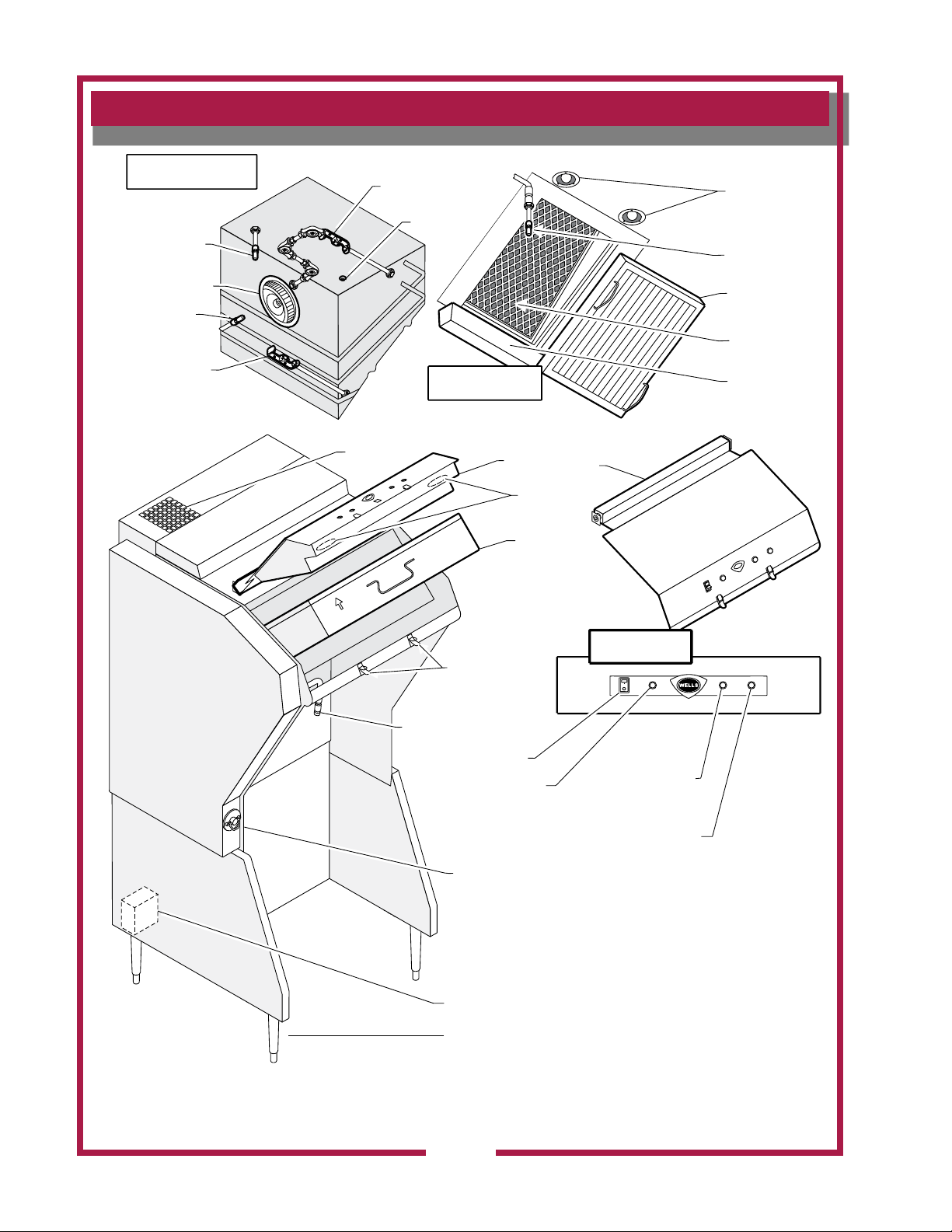
FEATURES & OPERATING CONTROLS
A
IR
F
L
O
W
FILTER PACK
(PARTIALLY
INSTALLED)
ANSUL® NOZZLE
ON SWIVEL
CONTROL PANEL/
FILTER ACCESS
SYSTEM
EXHAUST
OUTLET
ADJUSTABLE LEG
ANSUL®
PULL STATION
ELECTRICAL
CONNECTION BOX
APPLIANCE
LIGHTS
AREA UNDER HOOD
(LOOKING UP)
FILTER PACK
(IN PLACE)
GREASE
BAFFLE
(REMOVED)
GREASE CUP
ANSUL® NOZZLE
ON SWIVEL
AREA BEHIND FILTERS
(LOOKING UP)
ANSUL® SERIES
DETECTOR W/
212ºF FUSIBLE LINK
ANSUL® SERIES
DETECTOR W/
165ºF FUSIBLE LINK
PRESSURE
SENSOR TAP
VENTILATOR
FAN
ANSUL®
NOZZLE
ANSUL®
NOZZLE
FILTER
GREASE BAFFLE
APPLIANCE
LIGHTS
CHECK FILTER CHANGE FILTER
SERVICE REQUIRED
LIGHTED POWER
SWITCH (GREEN)
"CHECK FILTERS"
FILTER(S) OUT OF
POSITION INDICATOR
(AMBER)
"REPLACE FILTERS"
FILTERS NEARING
END OF SERVICE LIFE
INDICATOR (AMBER)
"SERVICE REQUIRED"
FILTERS EXPENDED
INDICATOR (RED -
SYSTEM SHUT DOWN)
CONTROL PANEL
PANEL LATCHES
IL1825 Rev. -
Universal Ventless Hood Features & Operating Controls
2
M521 p/n 2M-Z17085 OpM WVU- Universal Hood
Page 5
PRECAUTIONS AND GENERAL INFORMATION
This ventilator hood is part of an engineered system and is intended for
use in commercial establishments only.
This ventilator is intended
in the preparation food for human consumption. No other use is
recommended or authorized by the manufacturer or its agents.
Operators of this appliance must be familiar with the appliance use,
limitations and associated restrictions. Operating instructions must be
read and understood by all persons using or installing this appliance.
This ventilator hood system is designed to reduce odor emissions,
but will not completely eliminate all cooking odors. Air exchange
rates at the installation site must comply with the requirements of the
local jurisdictional authority. To ensure that odors do not accumulate,
recommended minimum air exchange is 400 cfm into and out of the
site.
This unit is intended for use with light- and medium duty electric
cooking appliances only. Cooking appliances placed under this
ventilator must comply with the restrictions set forth in the Installation
Instructions included in the literature package shipped with the unit.
Also see Under Hood Cooking Appliance Limitations, page 1.
Do not connect or energize this appliance until all installation
instructions are read and followed. Damage to the ventilator and/or
cooking appliances may result if these instructions are not followed.
Disconnect this appliance from electrical power before performing any
maintenance or servicing.
Cleanliness of this appliance is essential to good sanitation. Read and
follow all included cleaning instructions and schedules to ensure the
safety of the food product.
This appliance is not jet stream approved. Do not direct water jet or
steam jet at this appliance, or at any control panel or wiring. Do not
splash or pour water on, in or over any controls, control panel or wiring.
Do not attempt to wash lter packs. Water will cause their immediate
failure and disable the ventilator.
Exposed surfaces of this appliance can be hot to the touch and may
cause burns.
Avoid storing ammable or combustible materials in, on or near the
ventilator or associated cooking appliance.
The technical content of this manual, including any wiring diagrams,
schematics, parts breakdown illustrations and/or adjustment
procedures, is intended for use by qualied technical personnel.
Any procedure which requires the use of tools must be performed by a
qualied technician.
All supplied instructions, diagrams, schematics, parts breakdown
illustrations, notices and labels must remain with the appliance if it is
sold or moved to another location.
M521 p/n 2M-Z17085 OpM WVU- Universal Hood
This appliance is made in the USA. Unless otherwise noted, this
appliance has American sizes on all hardware.
for commercial establishments for use
DANGER:
SUFFOCATION HAZARD
Do not attempt to use this
ventilator with gas-red units.
This ventilator will not remove
products of combustion.
Unvented exhaust gasses
can be deadly.
WARNING:
SHOCK HAZARD
All servicing requiring
access to non-insulated
electrical components must
be performed by a factory
authorized technician.
DO NOT open any access
panel which requires the use
of tools. Failure to follow this
warning can result in severe
electrical shock.
IMPORTANT:
The ventilator is disabled
when the lters are plugged
to the point of insufcient
airow for proper operation.
Also, power to the cooking
appliances is interrupted if
either the lter pack or the
grease bafe is removed.
It is the responsibility of
the store management to
maintain sufcient spares
of lter packs to avoid
prolonged shutdown of the
ventilator when this lter
pack is expended. Filter
packs cannot be cleaned.
Wells Manufacturing
assumes no liability for loss
of business due to lter
related shutdown.
3
Page 6
AGENCY LISTING INFORMATION
This appliance conforms to NSF Standard 4 for sanitation only if
installed in accordance with the supplied Installation Instructions
and operated and maintained in accordance with the instructions in this
manual.
STD 4
UL710B
This appliance is ETL listed.
Recurculating System
INSTALLATION
NOTE: DO NOT discard
the carton or other packing
materials until you have
inspected the appliance for
hidden damage and tested it
for proper operation.
Refer to SHIPPING DAMAGE
CLAIM PROCEDURE on the
inside front cover of this
manual.
WARNING:
RISK OF INJURY
Installation procedures must
be performed by a qualied
technician with full knowledge
of all applicable electrical
codes. Failure can result in
personal injury and property
damage.
IMPORTANT:
Fire suppression system must
be charged and certied by an
authorized Ansul® distributor.
Ventilator will not operate and
cooking appliance will not be
energized until the Ansul® re
suppression system has been
charged.
UNPACKING & INSPECTION
Carefully remove the appliance from the carton. Remove all
protective plastic lm, packing materials and accessories from the
appliance before connecting electrical power or otherwise performing
any installation procedure.
Carefully read all instructions in this manual and the Installation
Instruction Sheet packed with the appliance before starting any
installation.
Read and understand all labels and diagrams attached to the
ventilator.
Carefully account for all components and accessories before
discarding packing materials.
COMPONENTS
Per module:
1 ea. Grease bafe
1 ea. Filter pack
1 ea Grease cup
Ansul® components - must be installed by an authorized ANSUL®
distributor only:
1 ea. Fire suppression agent tank
1 ea. Fire suppression agent (Ansulex® Low pH) 1.5 gal.
1 ea. Fire suppression system charging cartridge
Store these components in a convenient place for later use.
IMPORTANT:
After cooking appliances
are positioned under the
hood, swivel nozzles must
be positioned per Ansul®
recommendations.
M521 p/n 2M-Z17085 OpM WVU- Universal Hood
4
Page 7
INSTALLATION (continued)
SERVICE TECHNICIAN INSTALLATION NOTES
This ventilator hood is to be used with light-duty and medium-duty
electrically powered cooking appliances only.
• DO NOT attempt to use this ventilator hood with gas-red units.
• DO NOT use this ventilator hood with electrical appliances whose
dimensions or wattage characteristics exceed those dened in the
Under Hood Cooking Appliance Limitations, page 1.
Installation and start up must be performed by an Authorized
Installation Company.
Ansul® Installer must complete the WARRANTY INITIATION form
(2M-303912) included with the unit for the warranty to begin, and record
installation particulars on the CUSTOMER SERVICE DATA form
located at the end of this manual.
IT IS THE RESPONSIBILITY OF THE INSTALLER TO verify that
this VENTILATOR installation is in compliance with the specications
listed in this manual, with local code requirements, and in accordance
with the STANDARD FOR VENTILATON CONTROL AND FIRE
PROTECTION OF COMMERCIAL COOKING OPERATIONS as
detailed in N.F.P.A 96 (current edition).
NOTE: Certain codes require FRYERS to be restrained with a
TETHER or other RESTRAINT DEVICE. If this ventilator is to be used
with a fryer, it is the RESPONSIBILITY OF THE INSTALLER to check
with the AUTHORITY HAVING JURISDICTION, in order to ascertain
the applicability of this requirement to this specic installation . Any
restraint device must allow access to the back and sides of the unit to
provide for servicing and maintenance, and must not interfere with the
operation of the re suppression system.
DANGER:
SUFFOCATION HAZARD
Do not attempt to use this
ventilator with gas-red units.
This ventilator will not remove
products of combustion.
Unvented exhaust gasses
can be deadly.
WARNING:
SHOCK HAZARD
All servicing requiring access to non-insulated electrical components must be
performed by a factory
authorized technician.
DO NOT open any access
panel which requires the use
of tools. Failure to follow this
warning can result in severe
electrical shock.
CAUTION:
RISK OF
DAMAGE
SETUP
Setup the appliance only on a rm, level, non-combustible surface.
Verify local codes for requirements. Concrete, tile, terrazzo or metal
surfaces are recommended. Metal over combustible material may not
meet code for non-combustible surfaces.
Verify vertical clearances. Unit requires a minimum of 96” (oor to
overhead) to allow for adequate air circulation and replacement of
lters. Combustible object from the top must be 99” or higher, or 3”
above the unit while the control panel door is open.
Verify that the unit sits rmly on all legs or casters depending on your
model. With a spirit level, check that the appliance is level front-toback and side-to-side. With the adjustable legs, adjust as required
to level the appliance. In order to prevent tipping or deection, legs
must be adjusted such that all legs are in rm contact with the oor.
Refer to the General Layout Data
Wells Technical Services “service@wells-bloomeld.com”). Maintain
required clearances between the appliance and adjacent combustible
M521 p/n 2M-Z17085 OpM WVU- Universal Hood
surfaces.
for required clearances (contact
5
DO NOT connect or
energize this appliance
until all installation
instructions are read and
followed. Damage to the
appliance will result if
these instructions are not
followed.
IMPORTANT:
If a remote pull station is to
be used, ventilator cannot be
moved without rst disabling
the remote pull station.
Contact your Ansul® agent
for details.
Page 8
INSTALLATION
DANGER:
SUFFOCATION HAZARD
Do not attempt to use this
ventilator with gas-red units.
This ventilator will not remove
products of combustion.
Unvented exhaust gasses
can be deadly.
WARNING
SHOCK HAZARD
Electrical connections must
be made by a licensed
electrician.
CAUTION:
FIRE HAZARD
HEALTH HAZARD
The cooking appliance must
be connected to the cooking
appliance contactor, the
control circuit of which is
controlled by the ventilator.
Failure to control cooking
appliances will provide no
protection in the event of a
re, nor will cooking vapors
and odors be contained in
the event of ventilator hood
malfunction.
ELECTRICAL INSTALLATION
Refer to the nameplate on the ventilator. Verify ELECTRICAL
SERVICE POWER. Voltage and phase must match the nameplate
specications, and available electrical service amperage must meet or
exceed the listed amperage. Refer to specications listed on page 1
of this manual.
The ground lug of this ventilator must be connected to a suitable
building ground.
Remove the lower rear panel to access the cooking appliance
contactor and building alarm relay. Remove the appropriate knockout,
then wire the cooking appliance to the LOAD side of the contactor.
NOTE: If the provided power cord is not used, it is the responsibility
of the electrical contractor to provide suitable wiring, exible or ridgid
conduit, and an appropriate strain relief.
The cooking appliance under the ventilator hood must be connected
to the LOAD side of the cooking appliance contactor, located in the
electrical connection box. The contactor functions control the cooking
applance in the event of ventilator malfunction or appliance re.
The ventilator provides a dry contact relay connection for a building re
management system. This pilot-duty relay may be required by local
re codes, however, Wells Bloomeld strongly recommends that such
system be properly utilized in any case.
The alarm relay is activated by the Ansul® re detection system. If the
installation includes a building alarm system, connect to either the N.O.
or N.C. contacts of the relay (as required by the building alarm system).
The ventilator will operate properly, and the control relay will be
energized, only when:
1. The VENTILATOR POWER SWITCH is “ON”.
2. The Ansul® Fire Suppression System is charged and armed.
3. The grease bafe and lter pack are in position and serviceable,
and the ventilator pressure sensing system is satised.
CAUTION:
SHOCK HAZARD
The ground lug of this
appliance must be connected
to a suitable building ground.
IMPORTANT:
Contact a licensed electrician
to install and connect electrical
power to the appliance.
IMPORTANT:
Damage due to being
connected to the wrong
voltage or phase is NOT
covered by warranty.
M521 p/n 2M-Z17085 OpM WVU- Universal Hood
6
Page 9
INSTALLATION
FIRE SUPPRESSION SYSTEM INSTALLATION
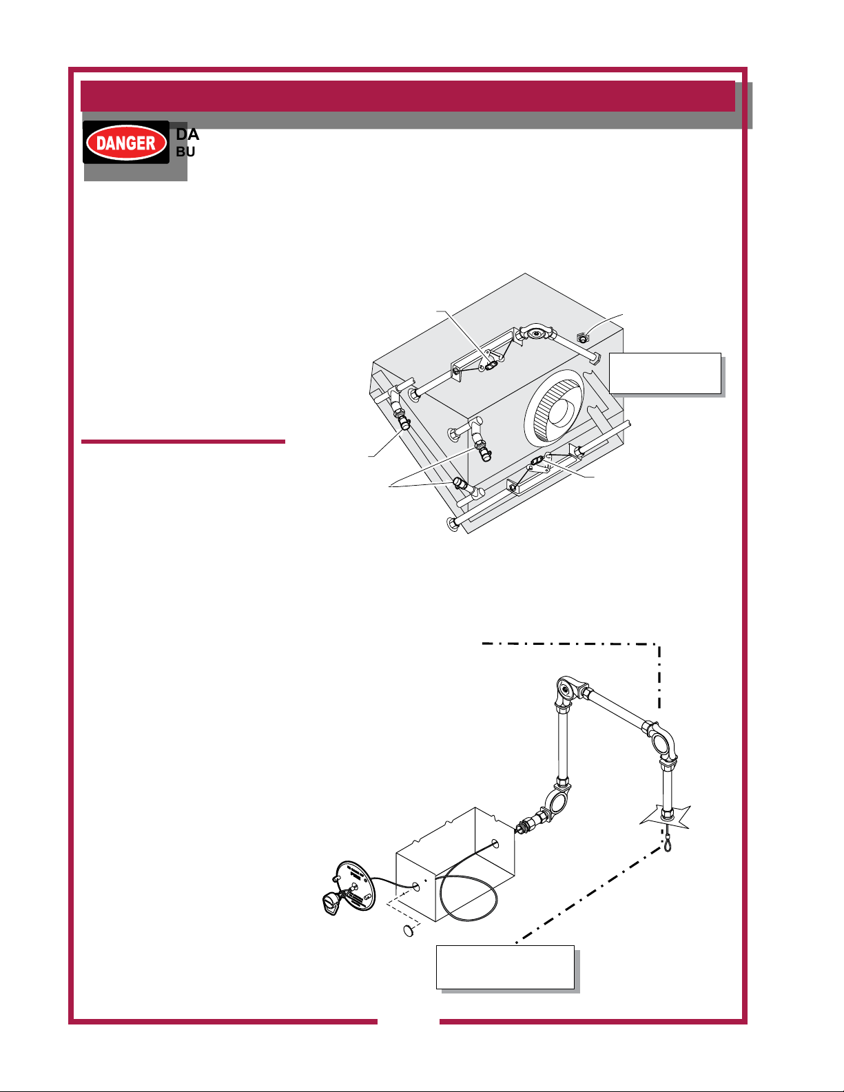
FIRE SUPPRESSION SYSTEM is comprised of a container of
Ansulex® Low pH liquid re suppression media and a system
pressurization canister for each module, plus associated plumbing.
Actuation controls are contained in the Automan enclosure.
Two FUSIBLE LINKS are utilized for automatic actuation of the re
suppression system. Additionally, the hood is supplied with a eld
installed MANUAL PULL STATION, which must be set-up at the time
of installation by an authorized Ansul® distributor.
The MANUAL PULL STATION allows for for manual emergency
shutdown of cooking appliance power, and actuation of the re
suppression system.
Three NOZZLES disperse the re suppression media. Two inner
nozzles protect the fan and plenum. The third, front mounted, nozzle
is swivel mounted, and must be directed toward the cooking surface
of the installed cooking appliance.
If the ventilator is situated such that the supplied manual pull
station cannot be installed or is not readily accessible, a REMOTE
MANUAL PULL STATION may be required by local codes. Any
such remote manual pull station must be installed by an authorized
Ansul® distributor in accordance with the AUTHORITY HAVING
JURISDICTION.
When the re suppression system discharges, cooking appliance
contactor and building re alarm relay are de-energized; and, the re
suppression media discharged. Fire supression media will form an
emulsion designed to both smother and cool the fuels in/on the cooking
appliance.
DANGER
FIRE HAZARD
Fire suppression system
must be charged and certied
by an authorized Ansul®
distributor.
DO NOT attempt to modify or
bypass the re suppression
system.
An uncontrolled re can
cause serious injury or death.
NOTE:
If the re suppression system
is discharged, a buzzer will
sound continuously. The unit
will remain inoperable until
the re suppression system is
serviced, recharged and reset
by an authorized Ansul®
distributor.
Charging of the Ansul®
Fire Suppression system
must be in accordance with
Ansul® Design, Installation,
Recharge and Maintenance
Manual, #418087.
NOTE:
If a REMOTE MANUAL PULL
STATION is installed, moving
the ventilator for any reason
may cause the Ansul®
system to discharge.
M521 p/n 2M-Z17085 OpM WVU- Universal Hood
IMPORTANT:
Should the re suppression
system discharge: all nozzles
must be replaced, and all
lines thoroughly cleaned,
prior to recharging the
system.
Residual re suppression
media may compromise the
ow and dispersion of re
suppression media in any
subsequent activation.
7
Page 10
INSTALLATION
INSTALL ON LEFT
IMPORTANT!
VACUUM FITTING
DO NOT INSTALL
DISCHARGE NOZZLE
HERE!
INSIDE OF HOOD
LOOKING UP
(FILTERS REMOVED)
212ºF
FUSIBLE LINK
FIXED
DISCHARGE
NOZZLES
SWIVEL
DISCHARGE
NOZZLE
INSIDE OF
HOOD
165ºF
FUSIBLE LINK
IL1817
DANGER
BURN HAZARD
Any additional remote pull
station must NOT be installed
on the front of the cooking
appliances, nor forward of the
ventilator side panels.
Discharge of the re
extinguishing system into hot
grease or oil may cause hot
foam to spill over from the
cooking surface or frypot.
Serious burns and other injuries
can result from contact with hot
oil and from slipping in spilled
oil.
Manual pull station is factory
installed on the left side (facing
the unit. It may, however,
be relocated to the right side
of the ventilator hood by an
authorized Ansul® agent.
Standard practice recommends
that the manual pull station be
located on the side toward an
exit.
FIRE SUPPRESSION SYSTEM INSTALLATION (continued)
Two fusible links are used to detect re. One (165ºF) is located
between the grease bafe and lter pack, and is for protection from
a cooking appliance re. The other (212ºF) is located in the lter
plenum, and will protect against a re in the plenum. Either link
melting will discharge the re suppression media through all nozzles,
disable the cooking appliance and cause a buzzer to sound.
The MANUAL PULL STATION and any similar REMOTE MANUAL
PULL STATION will activate the re suppression system when the
ring on the pull station is pulled to its full extent.
8
SIDE OF HOOD
MANUAL PULL
STATION PIPING
M521 p/n 2M-Z17085 OpM WVU- Universal Hood
IL1819
Page 11
INSTALLATION
CONTROL PANEL/
FILTER ACCESS PANEL
FILTER INSTALLATION
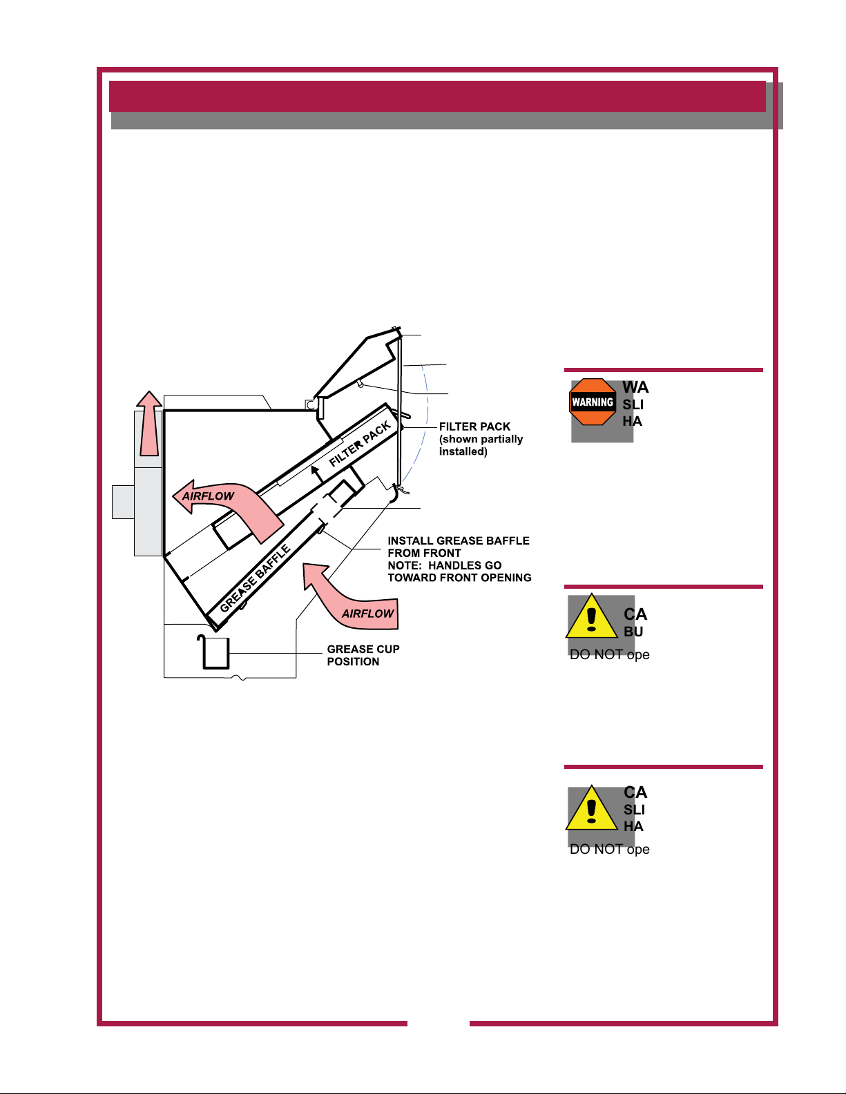
1. Release two catches holding control panel/lter access panel. Lift the
panel and raise the Prop Panel Rod to support and secure the panel in
the raised position.
2. Note air ow direction arrow on lter pack. Remove old lter pack
and slide new lter pack fully into the appropriate slot. Verify that
the airow arrow points toward the fan.
Use the provided handle to raise and lower the lter pack.
3. Raise the panel and put the Prop Panel Rod back to its lowered
position, then lower the panel and secure the catches.
PANEL SUPPORT
FILTER POSITION
SWITCH
A
IR
F
LO
W
FAN
GREASE BAFFLE
POSITION SWITCH
NOTE:
The GREASE BAFFLE
and FILTER PACK actuate
position switches when they
are properly positioned. They
must be properly installed
for the under hood cooking
and appliance contactor to be
energized.
WARNING
SLIP AND FALL
HAZARD
DO NOT operate any
grease-producing cooking
appliance
(e.g. fryer or griddle) unless
the grease cup is properly
installed. Oil will drip onto
oor creating a slipping
hazard.
GREASE BAFFLE and GREASE CUP INSTALLATION
1. Install grease bafe from front. Engage the bafe in the retainer
slot. Push up until the bafe bottom clears the lower lip of the
retainer, then lower the bafe into the bottom retainer
2. Install GREASE CUP into brackets below grease bafe.
3. Install CONDENSATION CUP in brackets at bottom skirt of hood.
Note: Failure to install GREASE CUP will allow grease and moisture
from GREASE BAFFLE to drop into hot cooking surfaces, creating
both a SAFETY HAZARD (hot oil splatter) and a HEALTH HAZARD
M521 p/n 2M-Z17085 OpM WVU- Universal Hood
(contamination of the cooking surface or cooking oil).
IL1818
CAUTION
BURN HAZARD
DO NOT operate any cooking
appliance unless the grease
cup is installed.
Moisture dripping onto hot
surfaces, oil or grease can
cause splattering.
CAUTION
SLIP AND FALL
HAZARD
DO NOT operate any
cooking appliance unless the
condensate cup is installed.
Moisture dripping onto oor
can cause a slip and fall
hazard.
9
Page 12
OPERATION
IL1820
ON DURING POWER UP
CAUTION:
HOT SURFACE
Exposed surfaces can be hot
to the touch and may cause
burns.
CAUTION:
SHOCK HAZARD
DO NOT splash or pour water
or grease onto control panel
or wiring.
IMPORTANT:
The ventilator and cooking
appliance control relay are
disabled when REPLACE
FILTERS light is illuminated.
Note that the ventilator
cannot operate if the lter
pack is removed.
It is the responsibility of
the store management to
maintain sufcient spares
of lter packs to avoid
prolonged shutdown of the
ventilator when this lter is
expended.
Filter packs cannot be
cleaned.
Wells Manufacturing
assumes no liability for loss of
business due to lter related
shutdown.
Control Panel
ON
POWER
OFF
CHECK
FILTER
REPLACE
FILTER
SERVICE
REQUIRED
NOTE: Cooking appliances must be operated in accordance with the
manufacturer’s instructions.
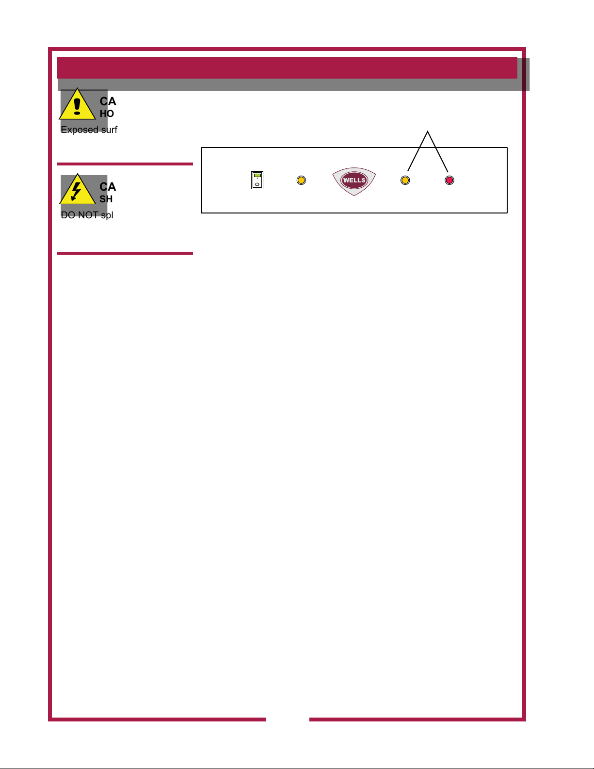
During normal operation, VENTILATOR POWER ON (illuminated power
switch) will be the only light on the control panel that will be ON, when
the unit is operating properly.
If the CHECK FILTERS light illuminates, check both GREASE BAFFLE
and the HEPA AIR FILTER for proper installation.
If REPLACE FILTER light illuminates, replace FILTER PACK.
NOTE: REPLACE FILTERS light is a warning that lter pack is nearing
the end of its service life. The ventilator will continue to operate for
a period of time after REPLACE FILTER LIGHT turns ON to allow
continued operation through a peak period. However, lter pack must
be replaced within a short time period or it will clog, disabling the
ventilator.
If SERVICE REQUIRED light illuminates, lter pack is restricted to
the point of insufcient airow for proper operation. Ventilator is shut
down until the underlying clogged lter situation has been corrected.
Replace clogged item with a fresh lter pack to correct the condition.
Reset the unit by turning VENTILATOR POWER SWITCH to OFF, then
back to ON.
A failure of incoming electric power will cause a shut down of the unit.
Reset the unit by turning VENTILATOR POWER SWITCH to OFF, then
back to ON.
Operation Lights
There are two equipment lights that will be on during normal operation.
M521 p/n 2M-Z17085 OpM WVU- Universal Hood
10
Page 13
CLEANING INSTRUCTIONS
PRECAUTIONS: Disconnect unit from electric power and allow to cool
Cover frypot to prevent oil contamination
FREQUENCY: Weekly
TOOLS: Mild detergent, clean non-abrasive towels
NOTE: Ventilator section to be cleaned in conjunction with cooking
appliance. Refer to appliance user instructions for cleaning procedure.
1. Disconnect unit from electric power and allow to cool.
Cover cooking appliance to prevent oil contamination.
2. Remove GREASE BAFFLE, GREASE CUP and CONDENSATE CUP.
3. Empty GREASE CUP and CONDENSATE CUP into an appropriate
grease collection receptacle.
4. Clean GREASE BAFFLE, GREASE CUP and CONDENSATE
CUP in a sink or dishwasher using mild detergent and warm water.
5. Dry components with a clean non-abrasive cloth. Reinstall
GREASE BAFFLE, GREASE CUP and CONDENSATE CUP in
ventilator.
CAUTION:
HOT SURFACE
Exposed surfaces can be hot
to the touch and may cause
burns. Allow unit to cool
before cleaning.
CAUTION:
SHOCK HAZARD
DO NOT splash or pour water
or grease onto control panel
or wiring.
6. Wipe exterior of ventilator with a clean cloth moistened with warm
water and mild detergent. Rinse by wiping with a clean cloth
moistened with warm water.
7. Uncover the cooking appliance and reconnect unit to electric power.
Procedure is complete
M521 p/n 2M-Z17085 OpM WVU- Universal Hood
11
Page 14
CLEANING INSTRUCTIONS
CAUTION:
HOT SURFACE
Exposed surfaces can be hot
to the touch and may cause
burns. Allow unit to cool
before cleaning.
CAUTION:
SHOCK HAZARD
DO NOT splash or pour water
or grease onto control panel
or wiring.
IMPORTANT:
DO NOT wash FILTER
PACK. Washing these lters
will clog them, and cause
installed cooking appliance
to be disabled.
PRECAUTIONS: Disconnect unit from electric power and allow to cool
Cover cooking surfaces and frypots to prevent
contamination.
FREQUENCY: Monthly
TOOLS: Mild detergent, clean non-abrasive towels
NOTE: Ventilator section to be cleaned in conjunction with cooking
appliance. Refer to appliance user instructions for cleaning procedure.
1. Disconnect unit from electric power and allow to cool.
Cover cooking applaince to prevent oil contamination.
2. Remove GREASE BAFFLE, GREASE CUP, CONDENSATE CUP and
FILTER PACK.
3. Wipe interior of ventilator with a clean cloth moistened with warm
water and mild detergent. Rinse by wiping with a clean cloth
moistened with warm water. DO NOT clean by spraying.
4. Dry ventilator thoroughly with a clean non-abrasive cloth.
IMPORTANT:
DO NOT clean interior of
ventilator by spraying.
Spraying can contaminate the
cooking appliance, and may
cause internal damage to the
ventilator blower, operation
proong system and/or re
suppression system.
Clean by wiping only.
Reinstall FILTER PACK, GREASE BAFFLE, GREASE CUP and
CONDENSATE CUP.
5. Uncover the cooking appliance and reconnect unit to electric power.
Procedure is complete
12
M521 p/n 2M-Z17085 OpM WVU- Universal Hood
Page 15

REQUIRED MAINTENANCE
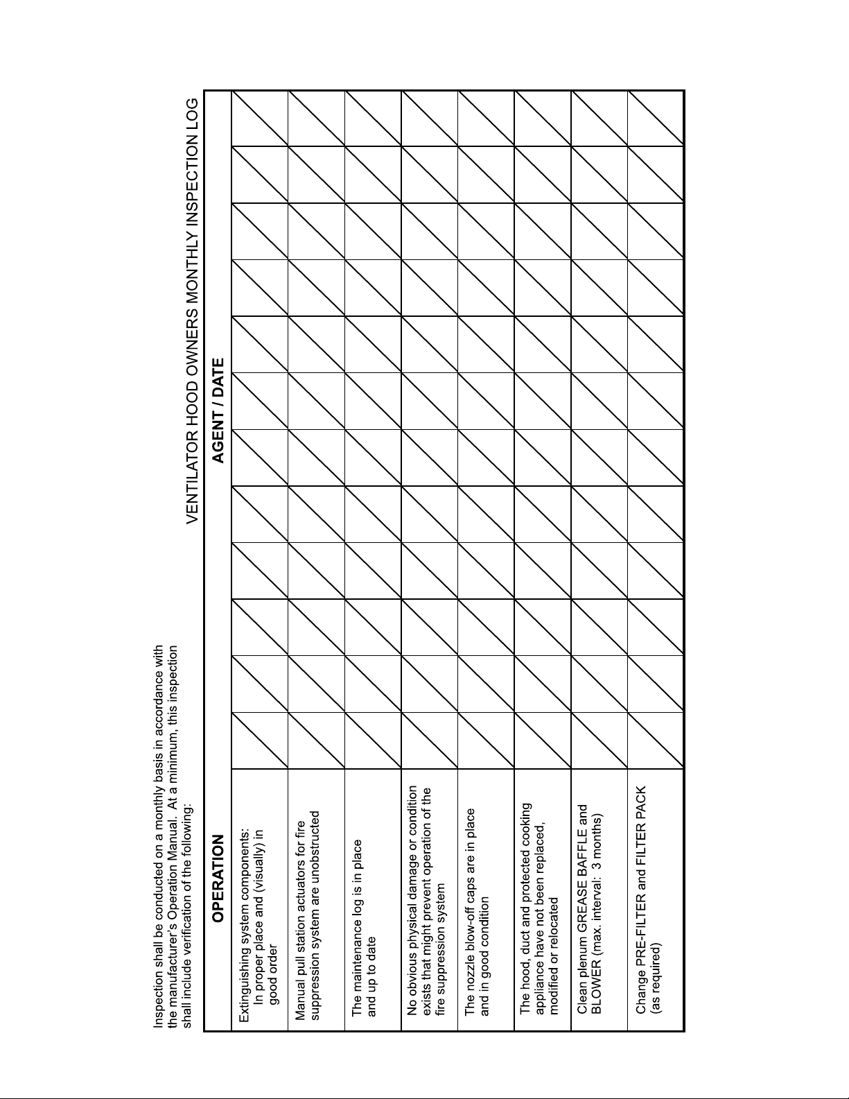
USE AND MAINTENANCE SHALL BE IN ACCORDANCE WITH THE
STANDARD FOR VENTILATION CONTROL AND FIRE PROTECTION
OF COMMERIAL COOKING OPERATIONS, N.F.P.A. 96 (current
edition).
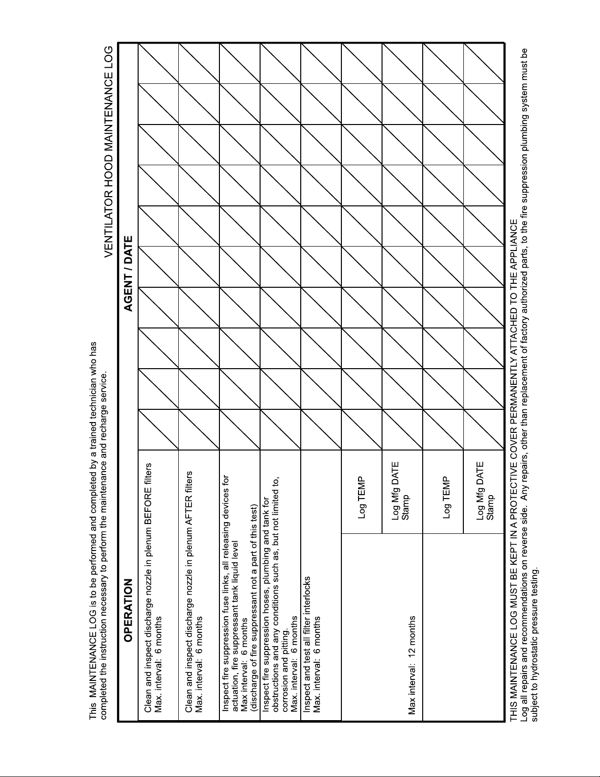
3-MONTH MAINTENANCE:
Thoroughly clean entire HOOD PLENUM and BLOWER section.
6-MONTH MAINTENANCE:
Inspection and testing of total operation including FIRE DAMPER and
all SAFETY INTERLOCKS shall be performed by qualied service
personnel.
All FIRE SUPPRESION SYSTEM actuation components including
MANUAL PULL STATION and any REMOTE MANUAL PULL STATION
must be inspected for proper operation in accordance with the
maintenance schedule published in
INSTALLATION, RECHARGE AND MAINTENANCE MANUAL (418087).
ANNUAL (12-MONTH) MAINTENANCE:
FIRE SUPRESSION SYSTEM FUSIBLE LINKS must be replaced.
NOZZLES and MANUAL PULL STATION must be cleaned in
accordance with
RECHARGE AND MAINTENANCE MANUAL (418087).
ANSUL® R-102 SYSYTEM DESIGN, INSTALLATION,
ANSUL® R-102 SYSTEM DESIGN,
IMPORTANT:
Per NFPS 96, a signed and
dated VENTILATOR HOOD
MAINTENANCE LOG
must be maintained on the
premises, and be made
available for inspection by the
authority having jurisdiction
upon request.
IMPORTANT:
Should the re suppression
system discharge, all
lines and nozzles must be
thoroughly cleaned prior to
recharging the system.
Be sure to note such cleaning
on the hood maintenance log.
Residual re suppression
media may compromise the
ow and dispersion of re
suppression media in any
subsequent activation.
12-YEAR MAINTENANCE:
The FIRE SUPRESSION AGENT TANK must be HYDROSTATICALLY
TESTED, and the FIRE EXTINGUISHING AGENT must be REPLACED
in accordance with the maintenance schedule published in ANSUL®
R-102 SYSTEM (STANDARD UL 300 LISTED). This maintenance to be
performed by qualied Ansul® service personnel only.
M521 p/n 2M-Z17085 OpM WVU- Universal Hood
13
Page 16
WELLS BLOOMFIELD, LLC
IL2144
14
M521 p/n 2M-Z17085 OpM WVU- Universal Hood
Page 17
WELLS BLOOMFIELD, LLC
IL2145
M521 p/n 2M-Z17085 OpM WVU- Universal Hood
15
Replace fire damper fusible link:
rated @ 280ºF
Replace two (2) fire suppression
links at cooking appliance:
each link is rated @ 165ºF
Max interval: 12 months
Page 18

16
M521 p/n 2M-Z17085 OpM WVU- Universal Hood
Page 19

M521 p/n 2M-Z17085 OpM WVU- Universal Hood
17
Page 20
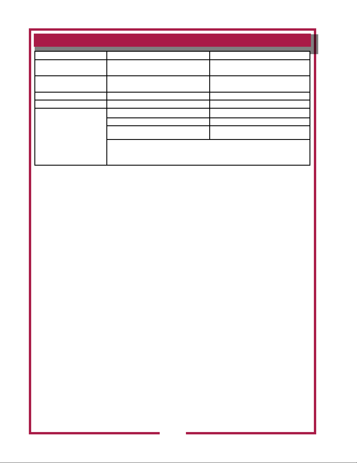
TROUBLESHOOTING SUGGESTIONS
Problem Possible Cause Suggested Remedy
Unit will not operate
(no indicators lights lit) Reset circuit breaker for unit
Unit will not operate
(buzzer sounds)
CHECK FILTER light lit Filter pack or grease bafe not in position Properly install lter pack and grease bafe
REPLACE FILTER light lit Filter pack nearing end of service life Arrange to replace lter pack in a timely manner
Fire damper in exhaust collar has closed Contact an authorized Wells service agent for repairs
SERVICE REQUIRED light lit (cooking
appliance not operating)
NOTE:
FILTERS are the only user serviceable components in this ventilator hood system. For all problems that cannot be remedied by
servicing the lters, contact:
Ventilator section - authorized Wells service agency
Fire suppression system - authorized Ansul® distributor
Disconnected from electric power
Fire suppression system not set Contact an authorized Ansul® distributor for repairs
Filter pack plugged Replace lter pack
One or more vacuum sensing lines or ports plugged, or
sensing line dislodged.
NOTE: If, after 10 seconds, there is insufcient airow for proper operation, SERVICE REQUIRED light will
illuminate and under-hood appliance (s) will be de-energized.
Press VENTILATOR POWER SWITCH to OFF, then back to ON to reset system.
Reconnect to electric power
Contact an authorized Wells service agent for repairs
IMPORTANT:
Contact ANSUL® for re suppression system installation, set-up and service:
Ansul Incorporated 1-800-TO-ANSUL (1-800-862-6785)
One Station Street
Marinette, WI 54143-2542 website http;//www.ansul.com
IMPORTANT:
Parts used in the Ansul® re suppression system are not serviceable by the owner/operator.
Procedures for servicing re suppression equipment are described in:
ANSUL® R-102 SYSTEM DESIGN, INSTALLATION, RECHARGE AND MAINTENANCE MANUAL
(418087, current edition)
NOTE:
ANSUL® Manual 41807 and Wells Bulletin 301646 are intended for use by authorized Ansul® service
personnel only.
M521 p/n 2M-Z17085 OpM WVU- Universal Hood
18
Page 21
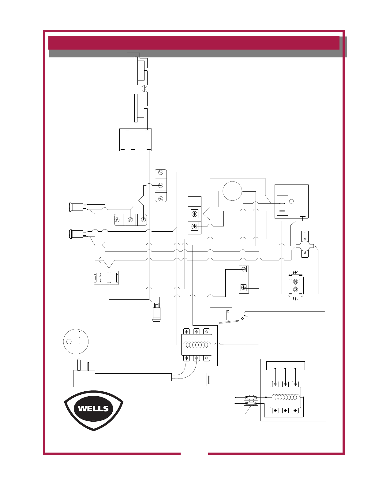
WIRING DIAGRAM
24V
208 / 240V
COM
HOOD MOUNTED 20W
APPLIANCE LIGHTS
REPLACE
FILTERS
LIGHT
(AMBER)
CHECK
FILTERS
LIGHT
(AMBER)
POWER
SWITCH
REQUIRES NEMA
6-15R
RECEPTACLE
(SINGLE PHASE)
#10
#11
#12
HEPA INTERLOCK SWITCH
2
1
#1
#6
GREASE
INTERLOCK
SWITCH
#14
COMMON
COMMON
NORMALLY
OPEN
NORMALLY
CLOSED
#6
#14
#27
#15
#7
#28
#9
CLOSED
#8
NORMALLY
NORMALLY
OPEN
#2
#12
VACCUM
SWITCH
(SHUTDOWN)
NORM
CLOSED
NORM
OPEN
COMMON
#12
#13
#16
MTR
#17
#19
#20
#5
#13
#25
#26
3
4
#6
#2
#5
#4
#26
#25
#15
SERVICE REQ
LIGHT (RED)
T1
T2 T3
COMMON
NORM
OPEN
NORM
CLOSED
VACCUM SWITCH
(REPLACE FILTER)
C
N.O.
N.C.
WIRING DIAGRAM WVU-1
208 /240V
#16
N.O.
#19
#18
#5
#22
#18
#13
#22
#12
#24
#3
1
2
TIMER
#21
#13
2
5
1
BUILDING
ALARM
RELAY
(NEUT.)
3
BUZZER
4
6
3
#24
#23
#3
#1
L1 L2 L3
#2
POWER TO UNDERHOOD APPLIANCES
M521 p/n 2M-Z17085 OpM WVU- Universal Hood
REV. (B) P/N 2M-Z13556
GROUND
TO (T1) AND (T2) OF
FACTORY MOUNTED
CONTACTOR
TERMINAL BLOCK FOR WIRING
CUSTOMERS CONTACTOR/S
(COILED WIRED IN PARALLEL
WIRING DIAGRAM WVU-1
208 /240V
19
T1
T2 T3
L1 L2 L3
W.D. # 2M-Z13556
DATE 6-11-13 REV-B
CUSTOMER
PROVIDED
CONTACTOR
MUST BE
208-240 VAC
Page 22
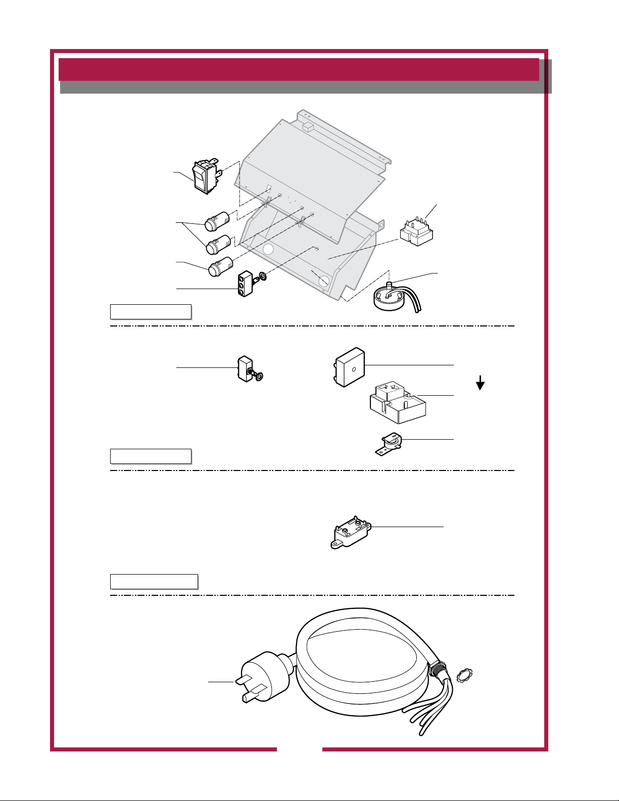
EXPLODED VIEW & PARTS LIST
LIGHT, APPLIANCE
NLA, replaced by
RELAY, BUILDING
IL1824 Rev. C 11/23/13
ELECTRICAL COMPONENTS
SWITCH, LIGHTED
GREEN 2E-305295
LIGHT, SIGNAL
AMBER 2J-30516
LIGHT, SIGNAL
RED 2J-31157
SWITCH, PLUNGER
2E-300407
CONTROL PANEL
TRANSFORMER
2E-Z5741
2E-Z13418
SWITCH, PLUNGER
2E-300407
UPPER CABINET
CONTACTOR (not shown)
208/240V w/SCREWS,
2E-37779
ELECTRICAL BOX
TIMER, CUBE
TIMER, CUBE
2P-Z17415
BUZZER 220V
2J-44834
FIRE ALARM
208-240V COIL
2E-44514
CORDSET
NEMA 6-15P
B8-307351
M521 p/n 2M-Z17085 OpM WVU- Universal Hood
20
Page 23
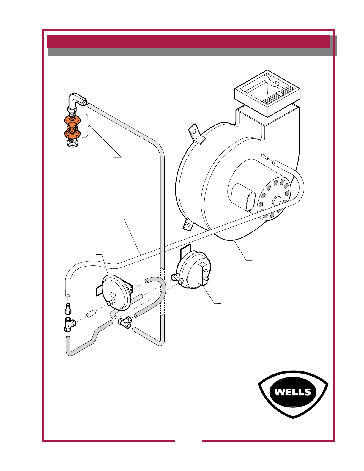
EXPLODED VIEW & PARTS LIST
IL1823 Rev. D 8/30/13
VACUUM SYSTEM COMPONENTS
FIRE DAMPER ASSY
212ºF (p/n. 2V-307913)
ref.QUICK-SEAL
ADAPTER 1/4"
ANSUL© p/n 2K-47100
VINYL TUBING 3/16" ID
p/n M3-303031
VACUUM SWITCH
(REPLACE FILTER)
p/n 2E-Z17173
M521 p/n 2M-Z17085 OpM WVU- Universal Hood
BLOWER
ASSEMBLY
p/n 2U-Z14025
VACUUM SWITCH
(SHUTDOWN)
p/n 2E-301379
21
Page 24
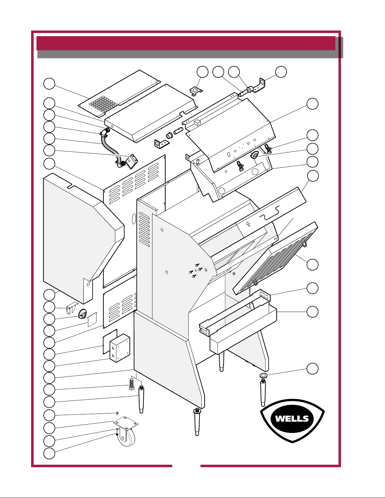
EXPLODED VIEW: WVU-1,
IL1822 Rev. B 5/21/13
A
IR
F
L
O
W
1
2
3
4
5
6
7
17
18 19 20
21
22
23
24
25
Door Prop Hole
26
27
28
30
WELLS
8
32
9
33
10
11
12
13
34
35
36
37
14
31
CABINET COMPONENTS
M521 p/n 2M-Z17085 OpM WVU- Universal Hood
22
Page 25
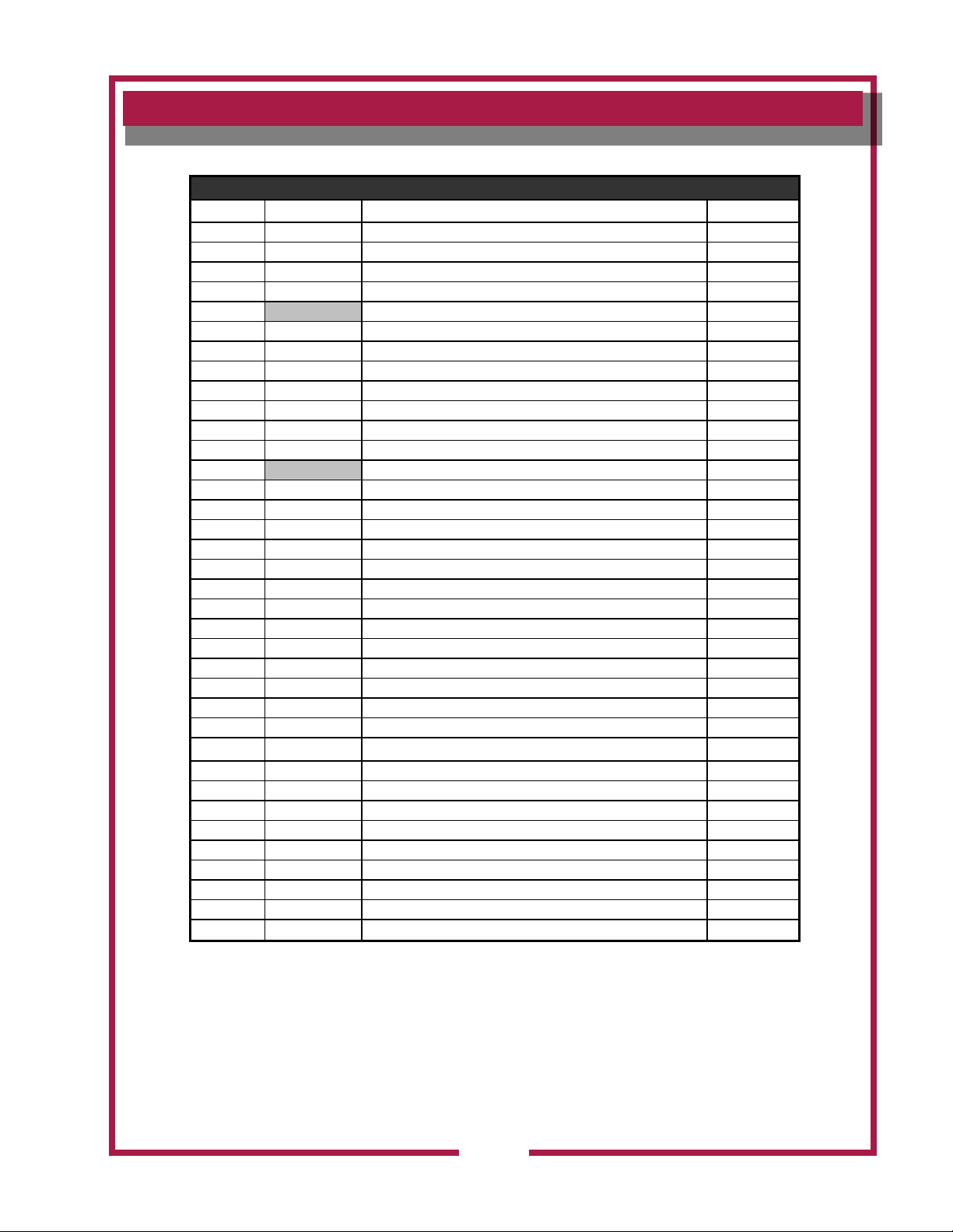
PARTS LIST: WVU-1, WVU-1P
CABINET COMPONENTS
WVU-1 CABINET COMPONENTS
ITEM PART NO. DESCRIPTION Application
1 N1-WL0397 PANEL. EXHAUST TOP
2 N1-Z17013 PANEL, TOP ELECTRICAL COVER
3 2I-Z12311 WASHER, FIBER
4 2K-34136X FITTING, CONDUIT 90º
5 CONDUIT
6 N1-Z13464 COVER, GREASE BAFFLE POSITION SWITCH
7 N1-Z17017 COVER, REAR UPPER
8 N1-Z13495 COVER, LEFT SIDE PANEL
9 2O-308131 ANSUL® MANUAL PULL STATION
10 N1-Z13456 COVER, REAR LOWER
11 N1-Z13455 COVER, ELECTRICAL BOX
12 N1-Z13454 OUTLET BOX, ELECTRICAL
13 CABINET (reference)
14 2A-307628 LEG, ADJUSTABLE 6” METAL (set of 4)
17 N1-Z13472 GUIDE, WIRING
18 2A-305610 PIN, PIVOT
19 2K-305619 BUSHING, PIVOT
20 N1-Z13471 BRACKET, PIVOT
21 N1-WL0395 COVER, CONTROL PANEL ASSY
22 2C-307939 LATCH ASSEMBLY, CONTROL PANEL
23 2M-306719 TRADEMARK, DIECAST
24 N1-WL0396 BASE, CONTROL PANEL, BOTTOM ASSY
25 N1-307923 FILTER PACK
26 2I-Z19216 GREASE BAFFLE
27 N1-Z17020 BRACKET, GREASE TRAY
28 N1-Z13496 GREASE TRAY
30 N1-Z13526 WASHER, FRONT LEG SEAL
31 2P-303417 CASTER WVU-1P
32 N1-Z17022 COVER BRACKET, PULL STATION WVU-1P
33 2L-Z17023 PULL STATION COVER CLEAR WVU-1P
34 2C-20104-24 SCREW HXHDCAP 1/2-13X1-12 WVU-1P
35 2C-Y1221 BOLT 1/4-20X1/2 HEX STL WVU-1P
36 2C-Z5556 WASHER, FLAT 1/4 SS WVU-1P
37 2C-6517 NUT 1/4-20 HEX STL NP WVU-1P
not shown
not shown
2M-Z13447 DECAL, CONTROL PANEL
2B-308146 PROP, CONTROL PANEL
M521 p/n 2M-Z17085 OpM WVU- Universal Hood
23
Page 26
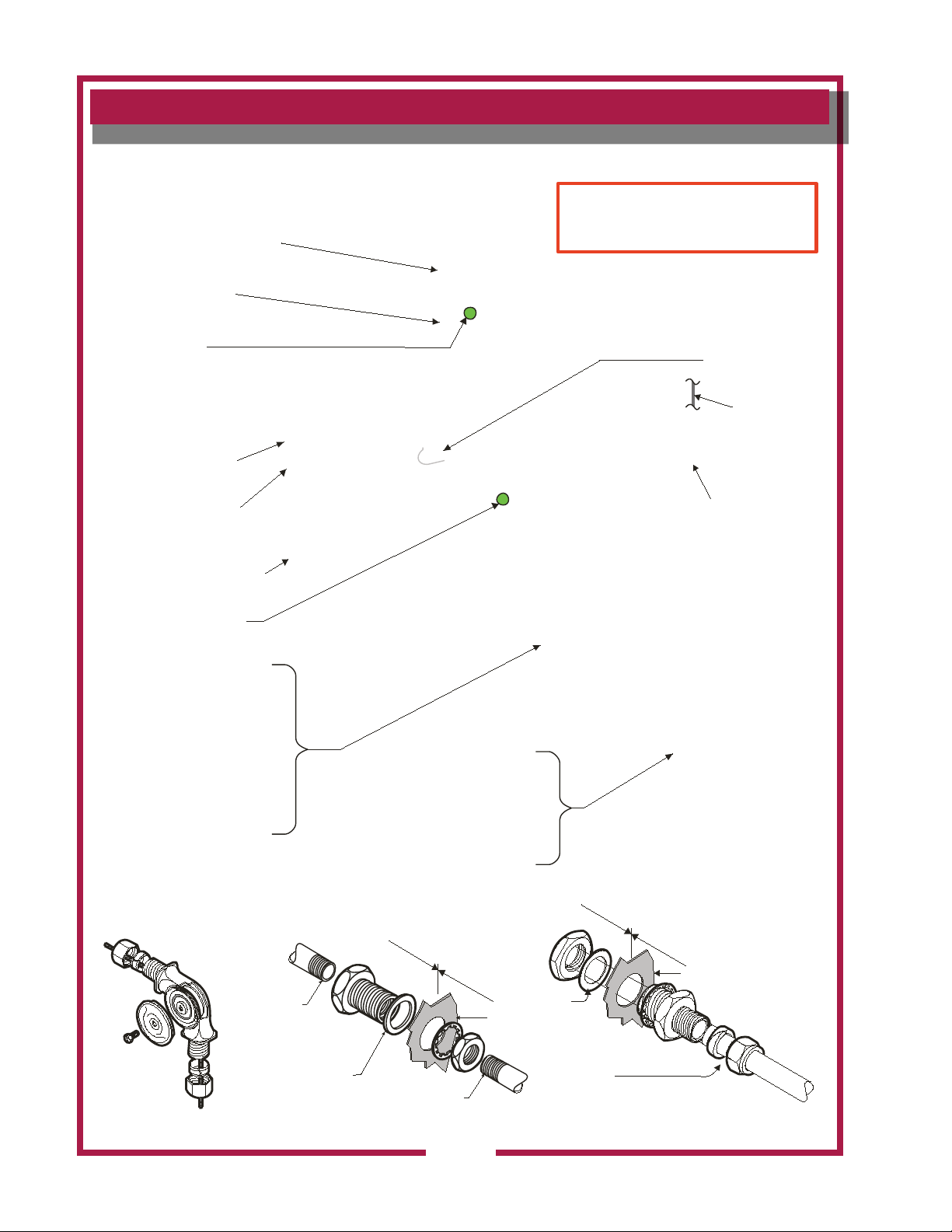
ANSUL® SYSTEM COMPONENTS
C ab le s its in
g ro o ve in
p ul le y
i
n
s
i
d
e
o
u
t
s
i
d
e
F ib er
w as h er
is al wa y s
o n the in s id e
c
o
n
d
u
i
t
w al l o f hood
C on d u it p a sse s co m pl ete ly
th ro u gh th e fitt in g, a n d is
se a le d wi th the c om p re s sio n
w as h er a nd n u t
F ib er w as he r
is al wa y s
o n the in s id e
w al l o f hood
Se a l w ith
te flo n ta pe
Se a l w ith
te flo n ta pe
I
N
S
I
D
E
O
U
T
S
I
D
E
A N SU L© p / n 4 2 32 50
DE TA IL
AN SU L© p /n 77 2 8 4
DE TA IL
AN SU L© p /n 79 1 5 2
DE TA IL
ref. AD A PT ER Q UIC K-S EA L 3 /8"
A NS UL © p/n 7 72 84 (typ ic al)
ref. N OZ ZLE 1W
A NS UL © p/n 4 19 336
ref. N OZ ZLE 1 W
A NS UL©
p/n 41 9336
FU SIB LE LIN K 21 2º F
p/ n 2E-30 303 7
FU SIB LE LIN K 16 5º F
p/ n 2E-30 258 3
ref. P ULL EY E LB OW
A NS UL© p/n 423 250
(t y pic al)
ref. S W IV EL AS S Y.
A NS UL © p/n 4 18 569
ref. N OZ ZLE 3N
A NS UL © p/n 419 33 8
M A NU A L P U L L STAT I O N
p/ n 2O-30 138 9
ref. MO UN TIN G B RA C KET
a nd R E L E ASE MEC HA N ISM
R -10 2 A NSU L © p /n 794 9 3
(n o t s how n)
C A R T R ID GE LT-20-R
A N S U L © p /n 2O-4709 9
(n o t s how n)
M IC ROSW I TC H p/n 2E-4727 3
TE RM B LO C K p /n 2E-330 6 8
ref. C AB LE
W IRE RO PE
A NS UL©
p/n 15 821
ref. TAN K 1 .5 GA L A N S U LEX ™
A N S U L © p /n 429 8 64
ref. (no t s h ow n)
A N S U L E X ™ E X T I NG UI S H I NG
A G E N T 1 .5 G A L .
A N S U L © p /n 796 9 4
F
R
O
N
T
O
F
U
N
I
T
FOR US E O NLY B Y AU TH OR IZ ED
AN S UL© S ER VIC E P E RSO NN E L
Refer to A nsu l© part no. 41 807 8-05
R-1 02 Rest aur an t Fire S upp ress ion S ystem De sig n,
Installation ,Re charg e and Ma int en ance
IL1821, Rev. A 6/08/10
24
M521 p/n 2M-Z17085 OpM WVU- Universal Hood
Page 27
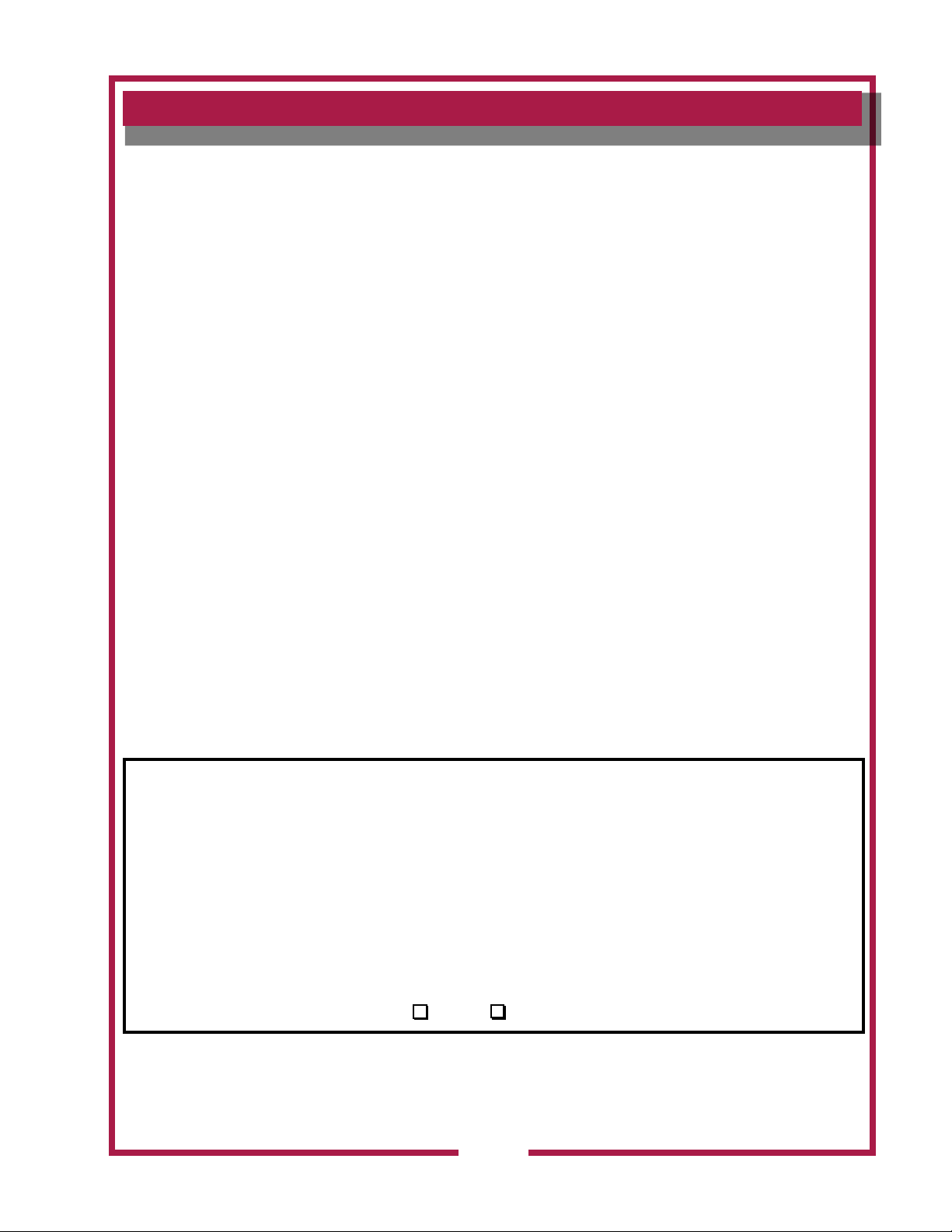
PARTS & SERVICE
DESCRIPTION PART NO.
FILTER PACK N1-307923
IMPORTANT: Use only
factory authorized service parts
and replacement lters.
For factory authorizedservice,
or to order factory authorized
replacement parts, contact
your Wells authorized service
agency, or call:
Wells Manufacturing
10 Sunnen Dr.
St. Louis MO 63143 USA
Service Dept.
phone: (314) 678-6314
fax: (314) 781-2714
Service Parts Department
can supply you with the name
and telephone number of
the WELLS AUTHORIZED
SERVICE AGENCY nearest
you.
CUSTOMER SERVICE DATA
please have this information available if calling for service
RESTAURANT _____________________________ LOCATION _____________
INSTALLATION DATE ________________________ TECHNICIAN ___________
SERVICE COMPANY ________________________________________________
ADDRESS ___________________________ STATE ______ ZIP__________
TELEPHONE NUMBER (_____)_____-_________
EQUIPMENT MODEL NO. _____________EQUIPMENT SERIAL NO. _______________
M521 p/n 2M-Z17085 OpM WVU- Universal Hood
VOLTAGE: (check one) 208 240
25
Page 28
WELLS MANUFACTURING
10 Sunnen Dr., St. Louis, MO 63143
telephone: 314-678-6314
fax: 314-781-2714
www.wellsbloomfield.com
 Loading...