

Page 1
531
OWNERS MANUAL
MODEL
WVSW
VENTLESS
HOOD
For
CONVEYOR
WARMERS
Includes
INSTALLATION
USE & CARE
SERVICE
IMPORTANT: DO NOT DISCARD THIS MANUAL
This manual is considered to be part of the appliance and is to be given to the OWNER or
MANAGER of the restaurant, or to the person responsible for TRAINING OPERATORS of
this appliance. Additional manuals are available from your WELLS DEALER.
THIS MANUAL MUST BE READ AND UNDERSTOOD BY ALL PERSONS USING OR
INSTALLING THIS APPLIANCE. Contact your WELLS DEALER if you have any
questions concerning installation, operation or maintenance of this equipment.
p/n 305812 Rev. (-) M531 012303 cps
Page 2

LIMITED WARRANTY STATEMENT
Unless otherwise specified, all commercial cooking equipment manufactured by WELLS MFG. CO. is warranted
against defects in materials and workmanship for a period of
one year from the date of original installation or 18 months
from the date of shipment from our factory, whichever
comes first, and is for the benefit of the original purchaser
only.
THIS WARRANTY IS THE COMPLETE AND ONLY WARRANTY, EXPRESSED OR IMPLIED IN LAW OR IN FACT,
INCLUDING BUT NOT LIMITED TO, WARRANTIES OF
MERCHANTABILITY OR FITNESS FOR ANY PARTICULAR PURPOSE, AND/OR FOR DIRECT, INDIRECT OR
CONSEQUENTIAL DAMAGES IN CONNECTION WITH
WELLS MFG. CO. PRODUCTS. This warranty is void if it
is determined that, upon inspection by an authorized service
agency, the equipment has been modified, misused, misapplied, improperly installed, or damaged in transit or by fire,
flood or act of God. It also does not apply if the serial nameplate has been removed, or if service is performed by unau-
SERVICE POLICY AND PROCEDURE GUIDE
ADDITIONAL WARRANTY EXCLUSIONS
1. Resetting of safety thermostats, circuit breakers, over
load protectors, and/or fuse replacements are not
covered by this warranty unless warranted conditions
are the cause.
2. All problems due to operation at voltages or phase
other than specified on equipment nameplates are
not covered by this warranty.
Conversion to correct voltage and/or phase must be
the customer’s responsibility.
3. All problems due to electrical connections not made
in accordance with electrical code requirements
and wiring diagrams supplied with the equipment are
not covered by this warranty.
4. Replacement of items subject to normal wear, to
include such items as knobs, light bulbs; and, normal
maintenance functions including adjustments of
thermostats, adjustment of micro switches and
replacement of fuses and indicating lights are not
covered by warranty.
5. Damage to electrical cords and/or plug due to exposure
to excessive heat are not covered by this warranty.
6. Full use, care, and maintenance instructions supplied
with each machine. Noted maintenance and
preventative maintenance items, such as servicing and
thorized personnel. The prices charged by Wells Mfg. Co.
for its products are based upon the limitations in this warranty. Seller’s obligation under this warranty is limited to the
repair of defects without charge by a Wells Mfg. Co. factory
authorized service agency or one of its sub-service agencies. This service will be provided on customer’s premises
for non-portable models. Portable models (a device with a
cord and plug) must be taken or shipped to the closest authorized service agency, transportation charges prepaid, for
service. In addition to restrictions contained in this warranty,
specific limitations are shown in the Service Policy and Procedure Guide. Wells Mfg. Co. authorized service agencies
are located in principal cities. This warranty is valid in the
United States and Canada and void elsewhere. Please consult your classified telephone directory, your foodservice
equipment dealer or write the Factory Service Department,
Wells Manufacturing Company, P.O. Box 280, Verdi, Nevada 89439, phone (775) 689-5700 or fax (888) 492-2783,
for information and other details concerning warranty.
cleaning schedules, are customer responsibility. Those
miscellaneous adjustments noted are customer
responsibility. Proper attention to preventative
maintenance and scheduled maintenance procedures
will prolong the life of the appliance.
7. Travel mileage is limited to sixty (60) miles from an
Authorized Service Agency or one of its sub-service
agencies.
8. All labor shall be performed during regular working
hours. Overtime premium will be charged to the buyer.
9. All genuine Wells replacement parts are warranted for
ninety (90) days from date of purchase on nonwarranty equipment. This parts warranty is limited only
to replacement of the defective part(s). Any use of
non-genuine Wells parts completely voids any
warranty.
10. Installation, labor, and job check-outs are not
considered warranty and are thus not covered by this
warranty.
11. Charges incurred by delays, waiting time or operating
restrictions that hinder the service technician’s ability to
perform service are not covered by warranty. This
includes institutional and correctional facilities.
SHIPPING DAMAGE CLAIM PROCEDURE
NOTE: For your protection, please note that equipment in
this shipment was carefully inspected and packaged by
skilled personnel before leaving the factory. Upon acceptance of this shipment, the transportation company assumes
full responsibility for its safe delivery.
IF SHIPMENT ARRIVES DAMAGED:
1. VISIBLE LOSS OR DAMAGE: Be certain that any
visible loss or damage is noted on the freight bill or
express receipt, and that the note of loss or damage is
signed by the delivery person.
2. FILE CLAIM FOR DAMAGE IMMEDIATELY:
Regardless of the extent of the damage.
3. CONCEALED LOSS OR DAMAGE: if damage is
unnoticed until the merchandise is unpacked, notify the
transportation company or carrier immediately, and file
“CONCEALED DAMAGE” claim with them. This
should be done within fifteen (15) days from the date
the delivery was made to you. Be sure to retain the
container for inspection.
Wells Manufacturing cannot assume liability for damage or
loss incurred in transit. We will, however, at your request,
supply you with the necessary documents to support your
claim.
xi
Page 3
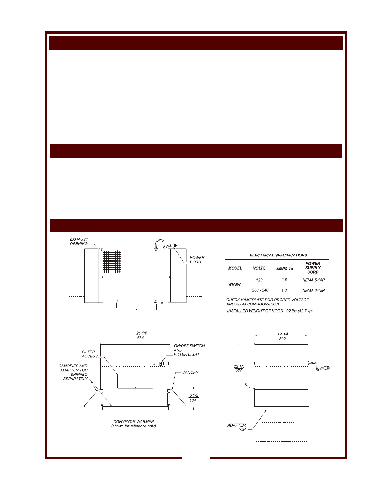
TABLE OF CONTENTS
WARRANTY xi
SPECIFICATIONS 1
FEATURES & OPERATING CONTROLS 2
AGENCY LISTING INFORMATION 3
PRECAUTIONS & GENERAL INFORMATION 4
INSTALLATION 5
OPERATION 7
CLEANING INSTRUCTIONS 8
TROUBLESHOOTING SUGGESTIONS 9
SERVICE INSTRUCTIONS 10
PARTS & SERVICE 11
CUSTOMER SERVICE DATA 11
INTRODUCTION
Thank You for purchasing this Wells Manufacturing Co. appliance.
Proper installation, professional operation and consistent maintenance of this appliance will ensure that it
gives you the very best performance and a long, economical service life.
This manual contains the information needed to properly install this appliance, and to use and care for the
appliance in a manner which will ensure its optimum performance.
SPECIFICATIONS
1
Page 4
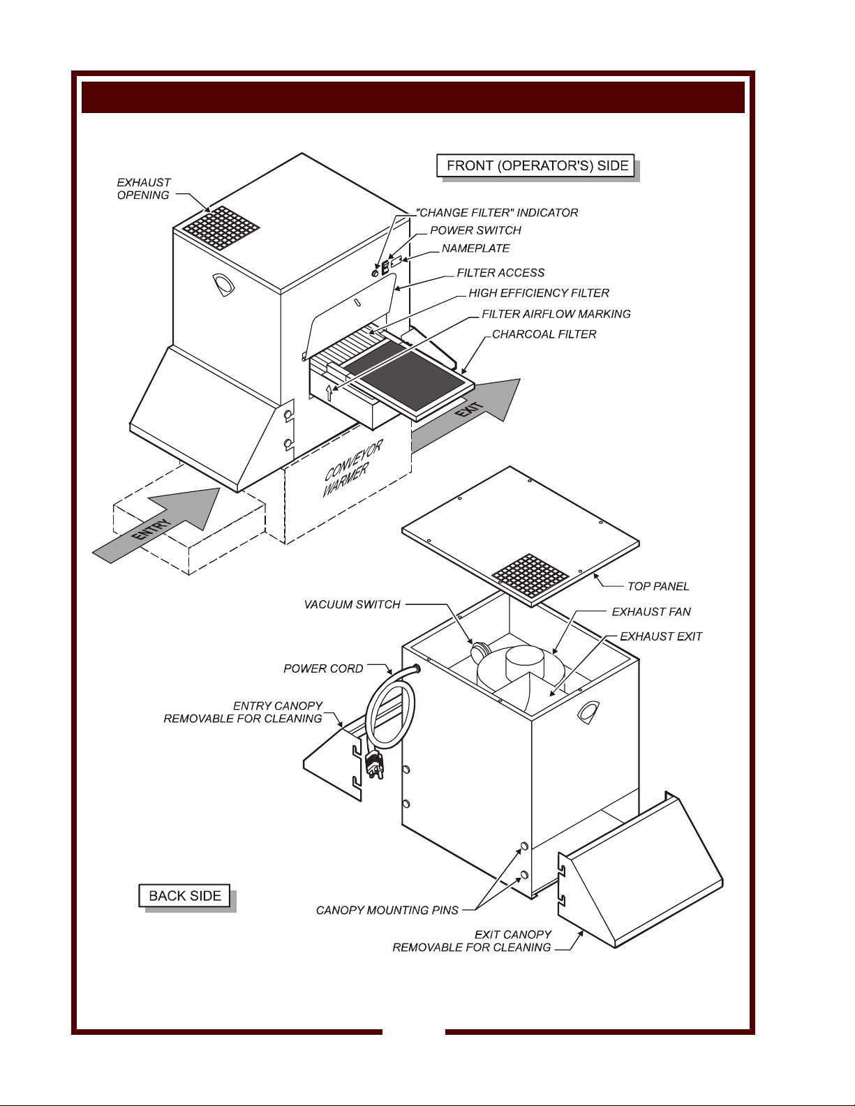
FEATURES & OPERATING CONTROLS
WVSW VENTLESS HOOD
Fig. 1 Features & Operating Controls
2
Page 5
FEATURES & OPERATING CONTROLS (continued)
ITEM DESCRIPTION
CANOPY Removable canopies aid in vapor capture at entry and exit of the conveyor
warmer. Canopies hang from mounting pins at each end of the hood.
ELECTRICAL The hood plugs into a NEMA 5-15R (120V) or 6-15R (208/240V) receptacle
with a 6' power cord. An illuminated power switch on the front panel is used
to start/stop the hood fan.
EXHAUST The hood uses an exhaust fan to provide air movement. The fan exhausts
through a screened opening in the top of the hood.
IMPORTANT: DO NOT block exhaust opening.
FILTERS The hood uses two filters. A high efficiency filter is used to capture
particulate emissions.
A charcoal filter is used to help control odors.
Filters are accessed by opening a hinged panel on the front (operator's)
side of the hood.
Filter operation is monitored by a vacuum switch. When the filter(s)
become loaded to the point of being unable to remove particulates, a front
panel "change filters" indicator will glow.
NAMEPLATE Provides Manufacturer, Model and Serial Number information.
Also, provides electrical ratings.
TOP PANEL
CAUTION!
Electric Shock Hazard
Exposed Electric Circuits
Top panel must be opened ONLY by qualified personnel.
Allows access to interior components.
DO NOT stack anything on top of the hood.
AGENCY LISTING INFORMATION
This appliance conforms to NSF Standard 4 for sanitation only if installed
and maintained according to the instructions in this manual.
This appliance is
This appliance is
IMPORTANT: For use with conveyor warmer of 9,000 watts maximum.
NOTE: This ductless hood has not been evaluated to the requirements of
NFPA 96.
Local jurisdictions may require additional evaluations for installation
of this product.
U Listed for 120V and 208 - 240V.
V Listed for 120V and 208 - 240V.
STD 4
3
Page 6

PRECAUTIONS AND GENERAL INFORMATION
WARNING:
Electric
Shock hazard
All servicing requiring
access to non-insulated
electrical components
must be performed by a
factory authorized
technician.
DO NOT open or remove
the top panel. Failure to
follow this warning can
result in severe electrical
shock.
CAUTION:
Risk of
Damage
DO NOT connect or
energize this appliance
until all installation
instructions are read and
followed. Damage to the
appliance will result if
these instructions are not
followed.
CAUTION:
Hot Surface
Exposed surfaces can be hot
to the touch and may cause
burns.
This appliance is intended for use in commercial establishments
only.
This appliance is intended
designed for use with specified warming equipment. No other use is
recommended or authorized by the manufacturer or its agents.
Operators of this appliance must be familiar with the appliance use,
limitations and associated restrictions. Operating instructions must be
read and understood by all persons using or installing this appliance.
Cleanliness of this appliance is essential to good sanitation. Read and
follow all included cleaning instructions and schedules to ensure the
safety of the food product.
Disconnect this appliance from electrical power before performing any
maintenance or servicing.
DO NOT submerge this appliance in water. This appliance is not jet
stream approved. Do not direct water jet or steam jet at this appliance,
or at any control panel or wiring. Do not splash or pour water on, in or
over any controls, control panel or wiring. Do not wash floor around
this appliance with water or steam jet.
Exposed surfaces of this appliance can be hot to the touch and may
cause burns.
The technical content of this manual, including any wiring diagrams,
schematics, parts breakdown illustrations and/or adjustment
procedures, is intended for use by qualified technical personnel.
Any procedure which requires the use of tools must be performed by a
qualified technician.
This manual is considered to be a permanent part of the appliance.
This manual and all supplied instructions, diagrams, schematics, parts
breakdown illustrations, notices and labels must remain with the
appliance if it is sold or moved to another location.
This appliance is made in the USA. Unless otherwise noted, this
appliance has American sizes on all hardware.
as a smoke and odor control device,
4
Page 7

INSTALLATION
UNPACKING & INSPECTION
Carefully read all instructions in this manual before starting any
installation.
Carefully remove the hood from the carton.
IMPORTANT: Appliance weighs 92 lbs (42.7 kg). Use appropriate
care when removing from carton and installing on conveyor warmer.
Remove all protective plastic film, packing materials and accessories
from the hood before connecting electrical power or otherwise
performing any installation procedure.
Read and understand all labels and diagrams attached to the hood.
Carefully account for all components and accessories before
discarding packing materials. Store all accessories in a convenient
place for later use.
COMPONENTS:
HIGH EFFICIENCY FILTER
CHARCOAL FILTER
COMPONENTS SHIPPED SEPARATELY
CANOPY (2 ea)
ADAPTER TOP
SETUP
The conveyor-style warmer requires an adapter top (shipped
separately) for mounting the hood. Place adapter top on warmer
before setting hood in place. Carefully place hood on top of warmer.
Orient hood so that power switch is on the same side as the power
switch of the warmer. Center hood over the body of the warmer as
shown in Fig. 2 below:
Fig. 2 Hood installation on warmer
Check high efficiency filter and charcoal filter for proper installation.
Charcoal filter slides into clips on the high efficiency filter. Airflow
marks must point "up".
Attach entry and exit canopies to pins on sides of hood. Canopies are
interchangeable and may be mounted at either end.
Maintain required clearances of at least 6" between the appliance and
adjacent combustible surfaces.
NOTE: DO NOT discard
the carton or other packing
materials until you have
inspected the hood for hidden
damage and tested it for
proper operation.
Refer to SHIPPING DAMAGE
CLAIM PROCEDURE on the
inside front cover of this
manual.
WARNING!
Risk of
Personal Injury
Installation procedures must
be performed by a qualified
technician with full knowledge
of all applicable electrical
codes. Failure can result in
personal injury and property
damage.
CAUTION!
Risk of
Personal Injury
and Property
Damage
Unplug conveyor warmer and
allow to cool before beginning
installation.
IMPORTANT:
Maintain required clearances
of at least 6" between the
appliance and adjacent
combustible surfaces.
Avoid storing flammable or
combustible materials in, on
or near the appliance.
5
Page 8

INSTALLATION (continued)
WARNING!
Electric
Shock hazard
All servicing requiring
access to non-insulated
electrical components
must be performed by a
factory authorized
technician.
DO NOT open any access
panel which requires the
use of tools. Failure to
follow this warning can
result in severe electrical
shock.
CAUTION!
Electrical Shock
The ground prong of the
power cord is part of a
system designed to protect
you against electric shock in
the event of internal damage.
DO NOT cut the ground
prong (large round prong) or
twist a blade to make the plug
fit an existing receptacle.
IMPORTANT:
Contact a licensed electrician
to install and connect
electrical power to the
appliance.
IMPORTANT:
Damage due to being
connected to the wrong
voltage or phase is NOT
covered by warranty.
Hazard
ELECTRICAL INSTALLATION
Refer to the nameplate. Verify the electrical power source. Voltage
and phase must match the nameplate specifications. Plugging the
hood into the wrong voltage can severely damage the unit .
Your hood is equipped with a grounded electrical cord. This cord
must be plugged into a properly grounded NEMA 5-15R (120V) or
NEMA 6-15R (208/240V) single phase receptacle.
Fig. 3 Electrical Plug and Receptacle Configuration
6
Page 9

OPERATING CONTROLS
Controls include a lighted POWER SWITCH and an amber REPLACE
FILTER indicator light.
Press POWER SWITCH to ON anytime conveyor warmer is operating.
When power is first turned on, the REPLACE FILTER light will glow.
As the fan comes up to speed and air flow is established, the REPLACE
FILTER light will go out.
If the REPLACE FILTER light does not go out, the filters must be
replaced. However, the fan will continue to operate when the
REPLACE FILTER light is lit.
FILTER REMOVAL AND INSTALLATION
Disconnect power from hood and conveyor warmer before servicing
filters.
Remove screw from filter access panel on front (operator's) side of
hood. Slide filter pack (high efficiency filter and charcoal filter) from
filter chamber.
Slide new filter pack into filter chamber. Be sure airflow markings on
both filters point "up".
Close access panel and reinstall screw.
IMPORTANT:
Filters are disposable. Never attempt to wash either filter.
Filters will absorb water if washed, causing food contamination and
possible equipment damage.
Fig. 5 Filter Installation
OPERATION
Fig. 4 Operating Controls
CAUTION!
Personal Injury
Hazard
Disconnect power from hood
and conveyor warmer before
servicing filters.
IMPORTANT:
DO NOT store anything on
top of the hood.
DO NOT block the exhaust
opening.
IMPORTANT:
Both the high efficiency and
charcoal filters must be in
place at all times during
operation.
7
Page 10

CLEANING INSTRUCTIONS
CAUTION!
Personal Injury
Hazard
Disconnect power from hood
and conveyor warmer before
cleaning.
IMPORTANT: DO NOT spill
or pour water into controls,
control panel or wiring.
DO NOT spill or pour water
into exhaust opening.
DO NOT submerge hood in
water or wash with water or
steam spray. Damage to
internal components will
occur.
Damage to internal
components from water
damage is not covered by
warranty.
PREPARATION Unplug hood and conveyor warmer
Allow to cool completely before cleaning
FREQUENCY Daily
TOOLS Mild Detergent
Soft Cloth or Sponge
1. Disconnect power from hood and conveyor warmer before cleaning.
2. Remove entry and exit canopies. Canopies may be washed in a
sink or dishwasher. Rinse and dry canopies thoroughly.
3. Wipe interior and exterior surfaces of hood with a soft cloth or
sponge dampened with water and a mild detergent.
IMPORTANT:
Never attempt to wash either filter.
Filters will absorb water if washed, causing food contamination and
possible equipment damage.
4. Rinse all washed areas by wiping with a clean soft cloth dampened
with clean water. Dry with a soft cloth.
5. Reinstall entry and exit canopies.
Procedure is complete
8
Page 11

TROUBLESHOOTING SUGGESTIONS
SYMPTOM PROBABLE CAUSE CORRECTIVE ACTION
No operation, no lights Cord unplugged
Circuit breaker off or tripped Reset circuit breaker
Damaged power cord or plug Replace power cord
Damaged power switch Replace power switch
REPLACE FILTER light remains
lit (never shuts off)
If filters are clean
and fan is operating
Exhaust opening blocked
Filter opening blocked Clear filter opening
Vacuum hose kinked Unkink vacuum hose
Filters dirty Replace filters
New filter still in plastic wrapper Remove plastic wrapper
Plug cord into appropriate power
receptacle.
Clear or clean exhaust duct and
opening
Vacuum line plugged Clean or replace vacuum line
Damaged vacuum switch Replace vacuum switch
If fan is not operating Fan jammed Unjam fan
Damaged motor start capacitor Replace start capacitor
Damaged fan motor Replace fan motor
9
Page 12

SERVICE INSRTUCTIONS
IMPORTANT:
DO NOT store anything on
top of the hood.
DO NOT block the exhaust
opening.
Filter operation is monitored
by a vacuum switch and a
system of vacuum hoses.
The switch energizes the
REPLACE FILTER light if
airflow through the filters is
insufficient for efficient
operation. The light is a
warning only, and does not
control the operation of the
hood.
VACUUM DIAGRAM
10
Page 13

PARTS & SERVICE
DESCRIPTION PART NO.
HIGH EFFICIENCY FILTER 16 x 20x 4 22862
CHARCOAL (CARBON) FILTER 14 x 20 x 7/8 22403
IMPORTANT: Use only
factory authorized service
parts and replacement
.
filters
For factory authorized
service, or to order factory
authorized replacement
parts, contact your Wells
authorized service agency,
or call:
Wells Manufacturing Co
2 Erik Circle
P. O. Box 280
Verdi, NV 89439
phone: (775) 689-5700
fax: (888) 492-2783
(Service Parts Dept.)
Service Parts Department
can supply you with the
name and telephone
number of the WELLS
AUTHORIZED SERVICE
AGENCY nearest you.
.
CUSTOMER SERVICE DATA
RESTAURANT _____________________________ LOCATION _____________
INSTALLATION DATE ________________________ TECHNICIAN ___________
SERVICE COMPANY ________________________________________________
ADDRESS ___________________________ STATE ______ ZIP__________
TELEPHONE NUMBER (_____)_____-_________
EQUIPMENT MODEL NO. _______________
EQUIPMENT SERIAL NO. _______________
VOLTAGE: (check one) 120 208 240
please have this information available if calling for service
11
Page 14

 Loading...