

Wells WV48FB Installation Manual
WELLS MANUFACTURING
10 Sunnen Dr., St. Louis, MO 63143
telephone: 314-678-6314
fax: 314-781-2714
www.wellsbloomfield.com
OWNERS MANUAL
VENTLESS
HOOD SYSTEM
ELECTRIC FRYERS &
BROILERS
COOKING
APPLIANCES
525
for
MODEL
WV48FB
Manual Includes
INSTALLATION
USE & CARE
EXPLODED VIEW
PARTS LIST
WIRING DIAGRAM
IL2372
IMPORTANT: DO NOT DISCARD THIS MANUAL
This manual is considered to be part of the appliance and is to be given to the OWNER or
MANAGER of the restaurant, or to the person responsible for TRAINING OPERATORS of
this appliance. Additional manuals are available from your WELLS DEALER.
THIS MANUAL MUST BE READ AND UNDERSTOOD BY ALL PERSONS USING OR
INSTALLING THIS APPLIANCE. Contact your WELLS DEALER if you have any
questions concerning installation, operation or maintenance of this equipment.
p/n 2M-Z17944 Rev.. A M525 150511

LIMITED WARRANTY STATEMENT
Unless otherwise specied, all commercial cooking
equipment manufactured by Wells Manufacturing is
warranted against defects in materials and workmanship
for a period of one year from the date of original installation
or 18 months from the date of shipment from our factory,
whichever comes rst, and is for the benet of the original
purchaser only.
THIS WARRANTY IS THE COMPLETE AND ONLY
WARRANTY, EXPRESSED OR IMPLIED IN LAW
OR IN FACT, INCLUDING BUT NOT LIMITED TO,
WARRANTIES OF MERCHANTABILITY OR FITNESS
FOR ANY PARTICULAR PURPOSE, AND/OR FOR
DIRECT, INDIRECT OR CONSEQUENTIAL DAMAGES
IN CONNECTION WITH WELLS MANUFACTURING
PRODUCTS. This warranty is void if it is determined
that, upon inspection by an authorized service agency,
the equipment has been modied, misused, misapplied,
improperly installed, or damaged in transit or by re, ood
or act of God. It also does not apply if the serial nameplate
has been removed, or if service is performed by unauthorized
personnel. The prices charged by Wells Manufacturing for
its products are based upon the limitations in this warranty.
Seller’s obligation under this warranty is limited to the
repair of defects without charge by a Wells Manufacturing
factory authorized service agency or one of its sub-service
agencies. This service will be provided on customer’s
premises for non-portable models. Portable models (a
device with a cord and plug) must be taken or shipped to the
closest authorized service agency, transportation charges
prepaid, for service. In addition to restrictions contained
in this warranty, specic limitations are shown in the
Service Policy and Procedure Guide. Wells Manufacturing
authorized service agencies are located in principal cities.
This warranty is valid in the United States and Canada and
void elsewhere. Please consult your classied telephone
directory, your foodservice equipment dealer or contact:
Wells Manufacturing
10 Sunnen Dr., St. Louis MO 63143 USA
phone (314) 678-6314 or fax (314) 781-2714
for information and other details concerning warranty.
SERVICE POLICY AND PROCEDURE GUIDE and ADDITIONAL WARRANTY EXCLUSIONS
1. Resetting of safety thermostats, circuit breakers, over
load protectors, and/or fuse replacements are not
covered by this warranty unless warranted conditions
are the cause.
2. All problems due to operation at voltages or phase
other than specied on equipment nameplates are
not covered by this warranty.
Conversion to correct voltage and/or phase must be
the customer’s responsibility.
3. All problems due to electrical connections not made
in accordance with electrical code requirements
and wiring diagrams supplied with the equipment are
not covered by this warranty.
4. Replacement of items subject to normal wear, to
include such items as knobs, light bulbs; and, normal
maintenance functions including adjustments of
thermostats, adjustment of micro switches and
replacement of fuses and indicating lights are not
covered by warranty.
5. Damage to electrical cords and/or plug due to exposure
to excessive heat are not covered by this warranty.
6. Full use, care, and maintenance instructions supplied
with each machine. Noted maintenance and
preventative maintenance items, such as servicing and
cleaning schedules, are customer responsibility. Those
miscellaneous adjustments noted are customer
responsibility. Proper attention to preventative
maintenance and scheduled maintenance procedures
will prolong the life of the appliance.
7. Travel mileage is limited to sixty (60) miles from an
Authorized Service Agency or one of its sub-service
agencies.
8. All labor shall be performed during regular working
hours. Overtime premium will be charged to the buyer.
9. All genuine Wells replacement parts are warranted
for ninety (90) days from date of purchase on non-
warranty equipment. This parts warranty is limited only
to replacement of the defective part(s). Any use of
non-genuine Wells parts completely voids any
warranty.
10. Installation, labor, and job check-outs are not
considered warranty and are thus not covered by this
warranty.
11. Charges incurred by delays, waiting time or operating
restrictions that hinder the service technician’s ability to
perform service are not covered by warranty. This
includes institutional and correctional facilities.
SHIPPING DAMAGE CLAIM PROCEDURE
NOTE: For your protection, please note that equipment
in this shipment was carefully inspected and packaged
by skilled personnel before leaving the factory. Upon
acceptance of this shipment, the transportation company
assumes full responsibility for its safe delivery.
IF SHIPMENT ARRIVES DAMAGED:
1. VISIBLE LOSS OR DAMAGE: Be certain that any
visible loss or damage is noted on the freight bill or
express receipt, and that the note of loss or damage is
signed by the delivery person.
2. FILE CLAIM FOR DAMAGE IMMEDIATELY:
Regardless of the extent of the damage.
3. CONCEALED LOSS OR DAMAGE: if damage is
unnoticed until the merchandise is unpacked, notify the
transportation company or carrier immediately, and le
“CONCEALED DAMAGE” claim with them. This
should be done within fteen (15) days from the date
the delivery was made to you. Be sure to retain the
container for inspection.
Wells Manufacturing cannot assume liability for damage or
loss incurred in transit. We will, however, at your request,
supply you with the necessary documents to support your
claim.
xi
M525 p/n 2M-Z17944 OpM WV48FB- Fryer & Broiler Ventless Hood
TABLE OF CONTENTS
WARRANTY xi
ELECTRICAL SPECIFICATIONS 1
FEATURES & OPERATING CONTROLS 2-3
PRECAUTIONS & GENERAL INFORMATION 4
AGENCY LISTING INFORMATION 5
INSTALLATION
Unpacking & Inspection 5
Components 5
Under-Hood Appliance Limitations 6
Service Technician Installation Notes 7
Base Assembly 8-9
Electrical Installation 10-11
ANSUL® INSTALLATION & SETUP 12-13
Filter Installation 14
OPERATION
Operation Lights 15
CLEANING INSTRUCTIONS 16-17
WIRING DIAGRAM 19
REQUIRED MAINTENANCE & MAINTENANCE LOGS 20-23
TROUBLESHOOTING SUGGESTIONS 24
EXPLODED VIEW & PARTS LIST 27-36
INTRODUCTION
Thank You for purchasing this Wells Manufacturing appliance.
Proper installation, professional operation and consistent maintenance of this appliance will ensure
that it gives you the very best performance and a long, economical service life.
This manual contains information and instructions for the ventless ventilation hood, its use and care.
For information regarding cooking appliance(s), please refer to the manufacturer’s operation manual.
ELECTRICAL SPECIFICATIONS
Model Volts Amps Power Supply
WV48FB
WV48FB-50HZ 4.3
M525 p/n 2M-Z17944 OpM WV48FB- Fryer & Broiler Ventless Hood
208/240V
3.5
For supply connection use #12 AWG copper wire only.
1
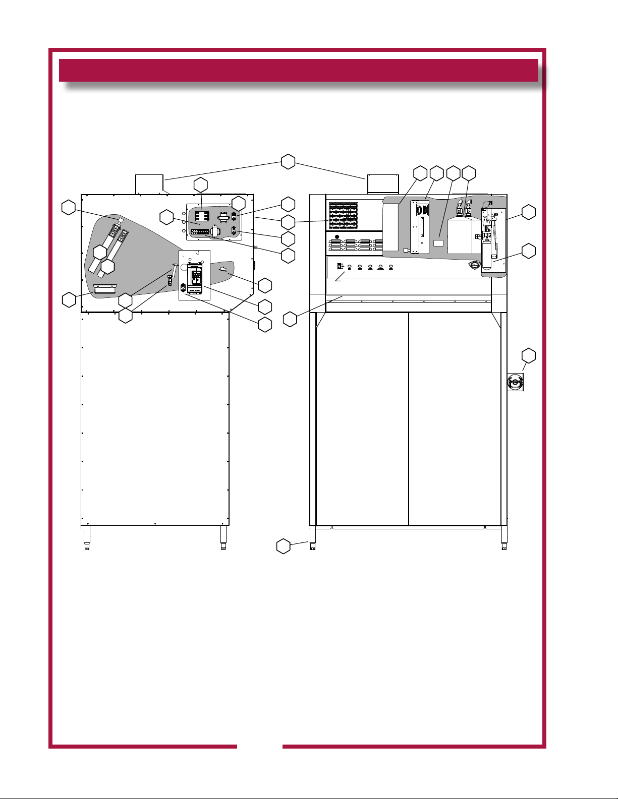
FEATURES & OPERATING CONTROLS
20
1
43 5 6
24
15
17
16
13
12
19
18
14
25
26
21
22
23
7
2
8
VENTILATOR CONTROL PANEL
see page 15
11
9
10
Ventilator Section Operating Features & Controls
2
IL2391a
M525 p/n 2M-Z17944 OpM WV48FB- Fryer & Broiler Ventless Hood
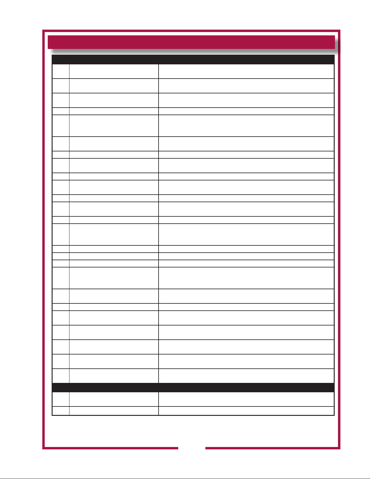
FEATURES & OPERATING CONTROLS continued
FEATURES & OPERATION CONTROLS
ITEM
NO
1 VENTILATOR EXHAUST DUCT, TOP Exit point for ventilator airow - on top of unit. DO NOT BLOCK
2 VENTILATOR EXHAUST DUCT, FRONT Exit point for ventilator airow - on front of unit. DO NOT BLOCK
3 VENTILATOR FAN Provides air movement for ventilation
HI-EFFICIENCY/CHARCOAL FILTER
4
PACK
DESCRIPTION COMMENT
Removes grease and smoke particles. Also assists in cooking odor removal.
5 NAMEPLATE
6 FIRE SUPPRESSION TANK Container for ANSUL® Low-pH Liquid re suppression uid.
7 ACTUATOR ASSY
8 ANSUL® CARTRIDGE Propels suppression liquid through suppression manifold and nozzles.
9 MANUAL PULL STATION
10 ADJUSTABLE LEGS Allows the unit to be leveled.
11 AIR WALL A wall of air that moves the grease and smoke particles into the lter system.
12 DISCHARGE NOZZLES Fire suppression media discharges here, (6 places 48”, 12 places 96”)
13 ELECTRICAL DETECTORS
14 APPLIANCE LIGHT ON when hood power switch is ON. Illuminates cooking area.
15 GREASE DRIP TRAY Collects grease/moisture dripping from bafe lter (16)
16 BAFFLE FILTER Extracts and drains most greases and moisture from the air ow.
17 PRE-FILTER ASSEMBLY
18 ELECTRICAL CONNECTION BOX Houses electrical components
19 GROUND LUG Ground wire of power connection connects here.
Gives manufacturer, make and model description. Also list voltage and amperage
data.
Triggers deployment of suppression uid through manual pull station or electric
detection.
Provides a means of manual activation of the re suppression system. PULL ONLY
IN CASE OF FIRE!
Designed to activate at certain temperature. Activates (i.e. re on the cooktop)
activates re suppression system. Should be checked every 6 months during
ANSUL® Service Inspection
Comprises the PRE-FILTER FRAME and a replaceable PRE-FILTER. Stops large
particles of grease from reaching the FILTER PACK for reduced maintenance costs.
20 EQUIPMENT INTERFACE CONTACTOR Energizes cooking appliances only while ventilator section is sensed as operational.
21 BUILDING FIRE ALARM RELAY Reports re alarm condition to building re management system.
22 DETECTION END OF LINE RELAY Prevents appliance operation if a fault is found in detection circuit.
23
24 FILTER INTERLOCK SWITCHES
25 VARIABLE FREQUENCY DRIVE Converts 50Hz to 60Hz, 1 Phase
M525 p/n 2M-Z17944 OpM WV48FB- Fryer & Broiler Ventless Hood
26 VFD RELAY Engauges VFD
SUPPLY CONNECTION TERMINAL
BLOCK
Provides connection point for electrical circuitry
Proper installation of bafe lter and lter pack closes these switches in ventilator
sensor circuit
50Hz UNITS
3
PRECAUTIONS AND GENERAL INFORMATION
This ventilator hood is part of an engineered system and is intended for
use in commercial establishments only.
This ventilator is intended
DANGER:
SUFFOCATION HAZARD
Do not attempt to use this
ventilator with gas-red units.
This ventilator will not remove
products of combustion.
Unvented exhaust gasses
can be deadly.
WARNING:
SHOCK HAZARD
All servicing requiring
access to non-insulated
electrical components must
be performed by a factory
authorized technician.
DO NOT open any access
panel which requires the use
of tools. Failure to follow this
warning can result in severe
electrical shock.
IMPORTANT:
The ventilator is disabled
when the lters are plugged
to the point of insufcient
airow for proper operation.
Also, power to the cooking
appliances is interrupted if
any lters or service panel
are removed.
It is the responsibility of
the store management to
maintain sufcient spares
of lter packs to avoid
prolonged shutdown due
to a dirty or clogged lter
pack. Filter packs cannot be
cleaned.
Wells Manufacturing
assumes no liability for loss
of business due to a lter
related shutdown. Spare
lters can be purchased
from any authorized Wells
servicer or calling Wells.
in the preparation food for human consumption. No other use is
recommended or authorized by the manufacturer or its agents.
Operators of this appliance must be familiar with the appliance use,
limitations and associated restrictions. Operating instructions must be
read and understood by all persons using or installing this appliance.
This ventilator hood system is designed to reduce odor emissions,
but will not completely eliminate all cooking odors. Air exchange
rates at the installation site must comply with the requirements of the
local jurisdictional authority. To ensure that odors do not accumulate,
recommended minimum air exchange is 200 cfm per linear foot of hood
into and out of the site.
This unit is intended for use with light- and medium duty electric
cooking appliances only. Cooking appliances placed under this
ventilator must comply with the restrictions set forth in the Installation
section of this manual.
Do not connect or energize this appliance until all installation
instructions are read and understood. Property damage or bodily
injury may result if these instructions are not followed. Disconnect this
appliance from electrical power before performing any maintenance or
servicing.
Cleanliness of this appliance is essential to good sanitation. Read and
follow all included cleaning instructions and schedules to ensure the
safety of the food product.
This appliance is not jet steam approved. Do not direct water jet or
steam jet at this appliance, or at any control panel or wiring.
Do not splash or pour water on, in or over any controls, control panel or
wiring. Do not attempt to wash lter packs. Water will cause their
immediate failure and disable the ventilator.
Exposed surfaces of this appliance can be hot to the touch and may
cause burns.
Avoid storing ammable or combustible materials in, on or near the
ventilator or associated cooking appliance.
The technical content of this manual, including any wiring diagrams,
schematics, parts breakdown illustrations and/or adjustment
procedures, is intended for use by qualied technical personnel.
Any procedure which requires the use of tools must be performed by a
qualied technician.
All supplied instructions, diagrams, schematics, parts breakdown
illustrations, notices and labels must remain with the appliance if the
unit is sold or moved to another location.
This appliance is made in the USA. Unless otherwise noted, this
appliance has American sizes on all hardware.
for commercial establishments for use
M525 p/n 2M-Z17944 OpM WV48FB- Fryer & Broiler Ventless Hood
4
AGENCY LISTING INFORMATION
SANITATION
This appliance conforms to NSF Standard 2 for sanitation only if
installed in accordance with the supplied Installation Instructions
and operated and maintained in accordance with the instructions in this
manual.
UL CLASSIFIED for use in US and Canada
NSF/ANSI 2
UL710B
Recurculating System
INSTALLATION
UNPACKING & INSPECTION
Carefully remove the appliance from the carton. Remove all
protective plastic lm, packing materials and accessories from the
appliance before connecting electrical power or otherwise performing
any installation procedure.
Carefully read all instructions in this manual and any other documents
packed with the appliance before starting any installation.
All documentation should remain with the equipment operator for future
reference.
Read and understand all labels and diagrams attached to the
ventilator.
Carefully account for all components and accessories before
discarding packing materials.
COMPONENTS
4 ft
Pre-Filter 2 ea.
Bafe Filter 2 ea.
Filter pack 1 ea.
Grease cup 1 ea.
Ansul® components - must be installed by an authorized Ansul®
distributor only:
4 ft
2 ea. Fire suppression agent tank
2 ea. Fire suppression agent (Ansulex® Low pH) 1.5 gal.
1 ea. Fire suppression system charging cartridge
Store these components in a convenient place for later use.
The unit is shipped congured for horizontal discharge of the exhaust.
To convert to vertical discharge:
1. Remove top access cover.
2. Remove internal turning vane.
3. Insert top discharge scoop assy and fasten w/hardware from cover.
4. Remove front discharge vent panel and damper assy.
5. Assemble damper in Top discharge scoop assy.
M525 p/n 2M-Z17944 OpM WV48FB- Fryer & Broiler Ventless Hood
6. Replace front discharge vent panel.
NOTE: DO NOT discard
the carton or other packing
materials until you have
inspected the appliance for
hidden damage and tested it
for proper operation.
Refer to SHIPPING DAMAGE
CLAIM PROCEDURE on the
inside front cover of this
manual.
WARNING:
RISK OF INJURY
Installation procedures must
be performed by a qualied
technician with full knowledge
of all applicable electrical
codes. Failure can result in
personal injury and property
damage.
IMPORTANT:
Fire suppression system must
be charged and certied by an
authorized Ansul® distributor.
Ventilator will not operate and
cooking appliance will not be
energized until the Ansul® re
suppression system has been
charged.
IMPORTANT:
After cooking appliances
are positioned under the
hood, swivel nozzles must
be positioned per Ansul®
recommendations.
5
INSTALLATION (continued)
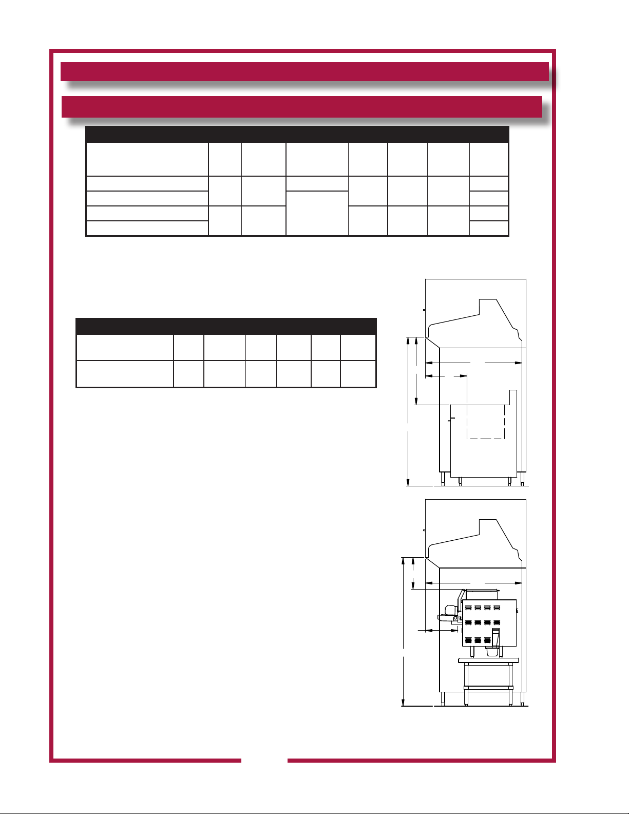
UNDER-HOOD APPLIANCE LIMITATIONS:
COOKING APPLIANCE LIMITATIONS
Acceptable Appliances by
Appliance Type
Single Vat Fryer
Multi Vat Fryer
Oven/Convection Oven
Steamer / Combi Oven 0
kW / Ft
Max
16.9
N/A
Max
Cooking
Temp
400°F
(204°C)
550°F
(287°C)
(1) Maximum single width 18”
(2) Front of hood to front edge of heated cooking surface.
(3) Bottom front edge of hood to height of heated cooking surface.
(4) Clearance from hood side panel to heated cooking surface.
SPECIFIC APPLIANCE LIMITATIONS
Specic Appliance
see notes (5) (6)
Input
Max
Max Temp
Setting
Dim D
Min (7)
NIECO Conveyor Broiler 7 Kw 500 15 14.5 18 0
Max Single
Heated Surface
Length
18
48
Dim E
Min (8)
Dim E
Max (8)
Dim
“A” (2)
Minimum
Dim
“B” (3)
Minimum
14 37 42
6 8 N/A
Dim F
Min (9)
B
Dim
“B” (3)
Maximum
Dim
“C” (4)
Minimum
0
0
0
BY APPLIANCE TYPE
48"
A
(5) Model JF91E with electrically interlocked exhaust catalyst.
(6) Meat paties must be frozen.
(7) Front edge of hood to front edge of heated chamber.
(8) Bottom edge of hoot to exhaust catayst.
(9) Clearance from hood side panel to broiler side.
All under hood appliances must be controlled by the equipment shutoff
interface. See owners manual pages 10-11 and wire diagram in supply
connection box. Only electrically heated appliances are acceptable for
installation. Appliance operation requires the re suppression system
be setup, charged and certied by an Authorized Ansul® Distributor.
The airow monitoring system will prevent appliance operation if
insufcient airow is detected or all lters are not in place.
The service panel must be in place for blower operation.
This hood and all under hood appliances must be installed in
accordance with the standard for ventilation control and re protection
of commercial cooking operations NFPA 96. The national electrical
code NFPA70 and all local codes where applicable.
Wells Manufacturing Model WV48FB
Lower Airow Limit: 1500 CFM
Broiler Maximum Measured Grease Emissions: 0.0063 LBS/HR/FT
Other Accepted Appliances: 0.0024 LBS/HR/FT
ANSI-UL710B Recirculating System UL Category YZCT FILE NO. MH4808
* The 10” - 12” leg option
increases the overall vertical
height.
74
NIECO MODEL JF91E
E
48"
D
74”
M525 p/n 2M-Z17944 OpM WV48FB- Fryer & Broiler Ventless Hood
IL2744
6
INSTALLATION (continued)
SERVICE TECHNICIAN INSTALLATION NOTES
This ventilator hood is to be used with light-duty and medium-duty
electrically powered cooking appliances only.
• DO NOT attempt to use this ventilator hood with gas-red units.
• DO NOT use this ventilator hood with electrical appliances whose
dimensions or wattage characteristics exceed those dened in the
Under Hood Cooking Appliance Limitations, page 6.
Installation and start up must be performed by an Authorized
Installation Company.
Ansul® Installer must complete the WARRANTY INITIATION form
(2M-303912) included with the unit for the warranty to begin, and record
installation particulars on the CUSTOMER SERVICE DATA form
located at the end of this manual.
IT IS THE RESPONSIBILITY OF THE INSTALLER TO verify that this
VENTILATOR installation is in compliance with the specications listed
in this manual, with local code requirements, and in accordance with
NFPA 96 the STANDARD FOR VENTILATION CONTROL AND FIRE
PROTECTION OF COMMERCIAL COOKING OPERATIONS.
NOTE: Certain codes require FRYERS to be restrained with a
TETHER or other RESTRAINT DEVICE. If this ventilator is to be used
with a fryer, it is the RESPONSIBILITY OF THE INSTALLER to check
with the AUTHORITY HAVING JURISDICTION, in order to ascertain
the applicability of this requirement to this specic installation .
SETUP
Setup the appliance only on a rm, level, non-combustible surface.
Verify local codes for requirements. Concrete, tile, terrazzo or metal
surfaces are recommended. Metal over combustible material may not
meet code for non-combustible surfaces.
Verify vertical clearances. Ceiling height shall be no less than 103”
inches when utilizing horizontal discharge option. Ceiling height shall
be no less than 120” inches when utilizing vertical discharge option.
Verify that the unit sits rmly on ALL LEGS. With a spirit level, check
that the appliance is level front-to-back and side-to-side. With the
adjustable legs, adjust as required to level the appliance. In order to
prevent tipping or deection, legs must be adjusted such that all legs
are in rm contact with the oor.
WARNING:
Equipment must be installed in accordance with the equipment
parameters table located on the service door. Fire suppression
sensors used on this unit provide superior re detection but are
sensitive to rapid temperature rise. To prevent unintentional
deployment of the re extinguishing system,
DO NOT move equipment from installed position when in use.
DO NOT power off hood when under hood equipment is HOT.
M525 p/n 2M-Z17944 OpM WV48FB- Fryer & Broiler Ventless Hood
DANGER:
SUFFOCATION HAZARD
Do not attempt to use this
ventilator with gas-red units.
This ventilator will not remove
products of combustion.
Unvented exhaust gasses
can be deadly.
WARNING:
SHOCK HAZARD
All servicing requiring
access to non-insulated
electrical components must
be performed by a factory
authorized technician.
DO NOT open any access
panel which requires the use
of tools. Failure to follow this
warning can result in severe
electrical shock.
CAUTION:
RISK OF
DAMAGE
DO NOT connect or energize
this appliance until all
installation instructions are
read and followed. Property
damage or bodily injury could
result if these instructions are
not followed.
IMPORTANT:
If a remote pull station is to
be used, ventilator cannot be
moved without rst disabling
the remote pull station.
Contact your Ansul® agent
for details.
7
INSTALLATION (continued)
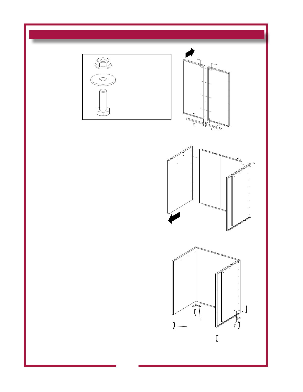
Hardware Provided
Front
Nut; 2C-6517
Washer; 2C-A27469
Bolt; 2C-Z5555
IL2977
BASE ASSEMBLY
Prior to assembling the base, locate it as close to the
nial position as possible. Then follow these steps.
1. Align the two rear panels (Fig 1) and secure with a
bolt, washer and nut (8 places).
2. Place the Base Bottom Stiffener (N1-Z15330) to the
bottom of the two rear panels and secure with bolt,
washer and nut (8 places).
3. Align the left and right side of the base to the rear
panel (Fig 2) and secure with bolt, washer and nut
(8 places each side).
4. Align the rear corner brackets in place (Fig 3) and
secure with bolt, washer and nut
(4 places each bracket).
5. Install the 6” adjustable legs and secure in place with
the bolt provided.
Front
Bottom Stiffener
IL2387
Figure 1
IL2388
Figure 2
Corner Bracket
6” Adj. Legs
IL2389
M525 p/n 2M-Z17944 OpM WV48FB- Fryer & Broiler Ventless Hood
Figure 3
8
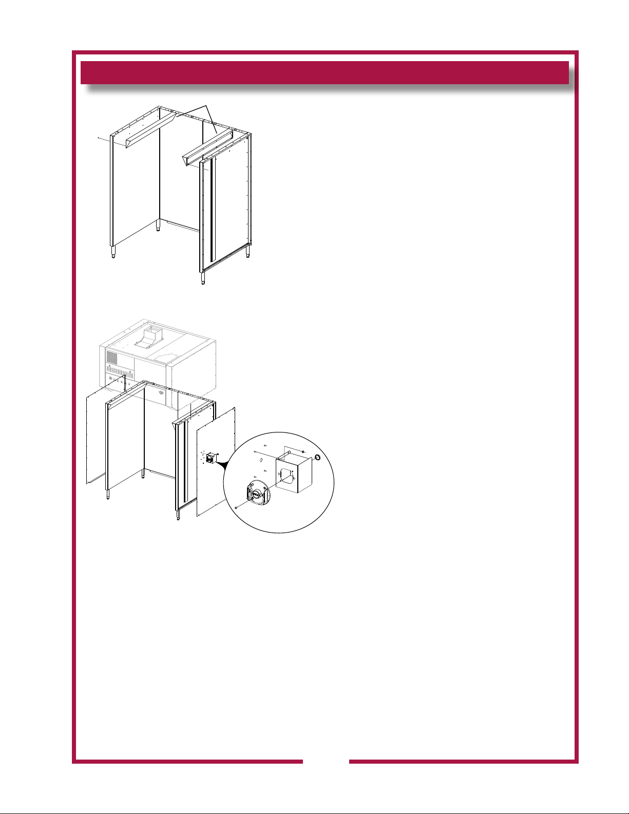
INSTALLATION (continued)
Base Deflectors
Figure 4
6. Align the two base deectors (Fig 4) in place and
secure with screws (8 per deector)
7. Move the base into position, and using a level,
adjust the legs until level.
8. Remove the side panels of the hood assembly so
when lowered onto the base assembly it will be
easier to secure in place.
9. Using the upper supporting brackets on the hood,
lower the hood on top of the base (Fig 5) so the
mounting holes line up. Secure with bolt, washer
and nut (7 places each side).
10. Contact your electrical & Ansul® contractors
to provide service to the system. Refer to
the ELECTRICAL INSTALLATION & FIRE
SUPPRESSION SYSTEM INSTALLATION
sections in this manual.
11. Once complete the side panels can be installed
using hardware provided.
M525 p/n 2M-Z17944 OpM WV48FB- Fryer & Broiler Ventless Hood
Figure 5
IL2743
9
 Loading...