

Wells WM-TR User Manual
WELLS MANUFACTURING COMPANY
2 ERIK CIRCLE, P. O. Box 280
Verdi, NV 89439
Customer Service (775) 345-0444 Ext.502
fax: (775) 345-0569
www.wellsbloomfield.com
OPERATION MANUAL
WATER-MAX
WM-TR
INSTALLATION
USE & CARE
705
Includes
IMPORTANT: DO NOT DISCARD THIS MANUAL
This manual is considered to be part of the appliance and is to be given to the OWNER or
MANAGER of the restaurant, or to the person responsible for TRAINING OPERATORS of
this appliance. Additional manuals are available from your WELLS DEALER.
THIS MANUAL MUST BE READ AND UNDERSTOOD BY ALL PERSONS USING OR
INSTALLING THIS APPLIANCE. Contact your WELLS DEALER if you have any
questions concerning installation, operation or maintenance of this equipment.
p/n 303560 Rev. B M705 012803 cps

LIMITED WARRANTY STATEMENT
Unless otherwise specified, all commercial cooking equipment manufactured by WELLS MFG. CO. is warranted
against defects in materials and workmanship for a period of
one year from the date of original installation or 18 months
from the date of shipment from our factory, whichever
comes first, and is for the benefit of the original purchaser
only.
THIS WARRANTY IS THE COMPLETE AND ONLY WARRANTY, EXPRESSED OR IMPLIED IN LAW OR IN FACT,
INCLUDING BUT NOT LIMITED TO, WARRANTIES OF
MERCHANTABILITY OR FITNESS FOR ANY PARTICULAR PURPOSE, AND/OR FOR DIRECT, INDIRECT OR
CONSEQUENTIAL DAMAGES IN CONNECTION WITH
WELLS MFG. CO. PRODUCTS. This warranty is void if it
is determined that, upon inspection by an authorized service
agency, the equipment has been modified, misused, misapplied, improperly installed, or damaged in transit or by fire,
flood or act of God. It also does not apply if the serial nameplate has been removed, or if service is performed by unau-
SERVICE POLICY AND PROCEDURE GUIDE
ADDITIONAL WARRANTY EXCLUSIONS
1. Resetting of safety thermostats, circuit breakers, over
load protectors, and/or fuse replacements are not
covered by this warranty unless warranted conditions
are the cause.
2. All problems due to operation at voltages or phase
other than specified on equipment nameplates are
not covered by this warranty.
Conversion to correct voltage and/or phase must be
the customer’s responsibility.
3. All problems due to electrical connections not made
in accordance with electrical code requirements
and wiring diagrams supplied with the equipment are
not covered by this warranty.
4. Replacement of items subject to normal wear, to
include such items as knobs, light bulbs; and, normal
maintenance functions including adjustments of
thermostats, adjustment of micro switches and
replacement of fuses and indicating lights are not
covered by warranty.
5. Damage to electrical cords and/or plug due to exposure
to excessive heat are not covered by this warranty.
6. Full use, care, and maintenance instructions supplied
with each machine. Noted maintenance and
preventative maintenance items, such as servicing and
thorized personnel. The prices charged by Wells Mfg. Co.
for its products are based upon the limitations in this warranty. Seller’s obligation under this warranty is limited to the
repair of defects without charge by a Wells Mfg. Co. factory
authorized service agency or one of its sub-service agencies. This service will be provided on customer’s premises
for non-portable models. Portable models (a device with a
cord and plug) must be taken or shipped to the closest authorized service agency, transportation charges prepaid, for
service. In addition to restrictions contained in this warranty,
specific limitations are shown in the Service Policy and Procedure Guide. Wells Mfg. Co. authorized service agencies
are located in principal cities. This warranty is valid in the
United States and Canada and void elsewhere. Please consult your classified telephone directory, your foodservice
equipment dealer or write the Factory Service Department,
Wells Manufacturing Company, P.O. Box 280, Verdi, Nevada 89439, phone (775) 345-0444 or (888) 492-2782, for
information and other details concerning warranty.
cleaning schedules, are customer responsibility. Those
miscellaneous adjustments noted are customer
responsibility. Proper attention to preventative
maintenance and scheduled maintenance procedures
will prolong the life of the appliance.
7. Travel mileage is limited to sixty (60) miles from an
Authorized Service Agency or one of its sub-service
agencies.
8. All labor shall be performed during regular working
hours. Overtime premium will be charged to the buyer.
9. All genuine Wells replacement parts are warranted for
ninety (90) days from date of purchase on nonwarranty equipment. This parts warranty is limited only
to replacement of the defective part(s). Any use of
non-genuine Wells parts completely voids any
warranty.
10. Installation, labor, and job check-outs are not
considered warranty and are thus not covered by this
warranty.
11. Charges incurred by delays, waiting time or operating
restrictions that hinder the service technician’s ability to
perform service are not covered by warranty. This
includes institutional and correctional facilities.
SHIPPING DAMAGE CLAIM PROCEDURE
NOTE: For your protection, please note that equipment in
this shipment was carefully inspected and packaged by
skilled personnel before leaving the factory. Upon acceptance of this shipment, the transportation company assumes
full responsibility for its safe delivery.
IF SHIPMENT ARRIVES DAMAGED:
1. VISIBLE LOSS OR DAMAGE: Be certain that any
visible loss or damage is noted on the freight bill or
express receipt, and that the note of loss or damage is
signed by the delivery person.
2. FILE CLAIM FOR DAMAGE IMMEDIATELY:
Regardless of the extent of the damage.
3. CONCEALED LOSS OR DAMAGE: if damage is
unnoticed until the merchandise is unpacked, notify the
transportation company or carrier immediately, and file
“CONCEALED DAMAGE” claim with them. This
should be done within fifteen (15) days from the date
the delivery was made to you. Be sure to retain the
container for inspection.
Wells Manufacturing cannot assume liability for damage or
loss incurred in transit. We will, however, at your request,
supply you with the necessary documents to support your
claim.
xi

TABLE OF CONTENTS
WARRANTY xi
SPECIFICATIONS 1
FEATURES & OPERATING CONTROLS 2
PRECAUTIONS & GENERAL INFORMATION 4
AGENCY LISTING INFORMATION 4
INSTALLATION 5
OPERATION 11
CLEANING INSTRUCTIONS 12
DELIMING INSTRUCTIONS 13
TROUBLESHOOTING SUGGESTIONS 16
PARTS & SERVICE 17
CUSTOMER SERVICE DATA 17
INTRODUCTION
Thank you for purchasing this Wells Manufacturing Co. appliance.
Proper installation, professional operation and consistent maintenance of this appliance will ensure that it
gives you the very best performance and a long, economical service life.
This manual contains the information needed to properly install this appliance, and to use and care for the
appliance in a manner which will ensure its optimum performance.
SPECIFICATIONS
Electrical: 208 Volts, Single Phase 35 Amps
240 Volts, Single Phase 35 Amps
NOTE: Requires a dedicated 50 Amp circuit
Plumbing: Water Inlet: 1/4” Male Flare Fitting
Supply: 1/4” Female Flare supplied by a 1/4” O.D. or larger water supply line
NOTE: If water supply run from main supply line to Water-Max™ exceeds 12 feet,
a 3/8” O.D. or larger water supply line is required.
For higher capacity, hook-up to a hot water line.
IMPORTANT: This dispenser must be installed in compliance with all applicable
federal, state and local codes and ordinances.
Dimensions: Height: 28-11/16”
Width: 10-1/16” (without tank) 15” (with tank installed)
Depth: 22-7/16” (without tank) 25-1/4” (with tank installed)
Weight: 74 lbs. (without tank) 150 lbs. (with tank installed and filled)
1
FEATURES & OPERATING CONTROLS
82
73
45
28
29
17
26
TAN K
(Typical)
74
44
42
71
25
1
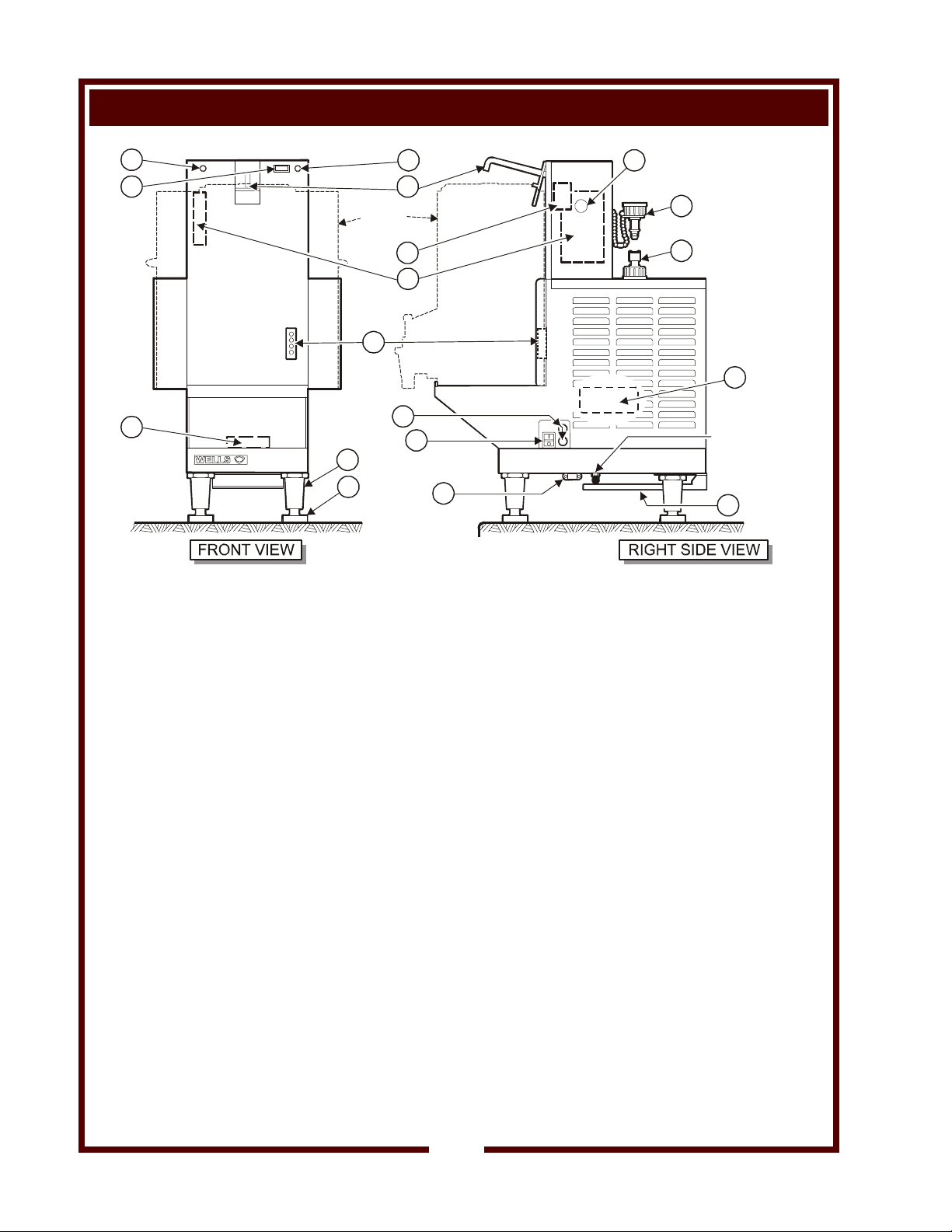
Fig. 1 Features & Operating Controls - Water Max™ Dispenser
78
79
13
90
WATER-MAX™
WATER INLET
FITTING
64
1. STRAIN RELIEF
13. DELIMING FITTING
17. TANK INDICATOR
25. POWER SWITCH
26. DISPENSER NOZZLE
28. ADJUSTABLE LEG
29. RUBBER FOOT
42. CONNECTOR
44. CONTROLLER
CIRCUIT BOARD
45. TERMINAL BLOCK
64. AIR OUTLET GUARD
71. FUSES
73. POWER INDICATOR
74. TANK POSITION
SWITCH
(Left Side, Bottom) Field supply wiring enters the appliance here.
Tank mounted quick disconnect fitting for deliming procedure.
Glows when tank is properly installed.
Energizes the appliance.
Hot water is dispensed here. Inserting water tank lowers nozzle into
“dispense” position.
Provides required clearance to counter, and allows unit to be leveled.
Allows Water-Max™ to operate without “walking” or sliding.
Allows WATER TANK to connect to Water-Max™.
Also provides power to keep tank contents hot.
(Inside left side) Access by qualified technician only.
(Inside, under tank shelf) Field supply wiring connects here.
Access by qualified technician only.
Provides a measure of protection for transformer cooling air outlet.
Provide protection for electrical circuits.
Glows when Water-Max™ is ON and operating normally.
Held ON when WATER TANK depresses DISPENSER NOZZLE.
Unit will not operate unless WATER TANK is in place.
2
FEATURES & OPERATING CONTROLS (continued)
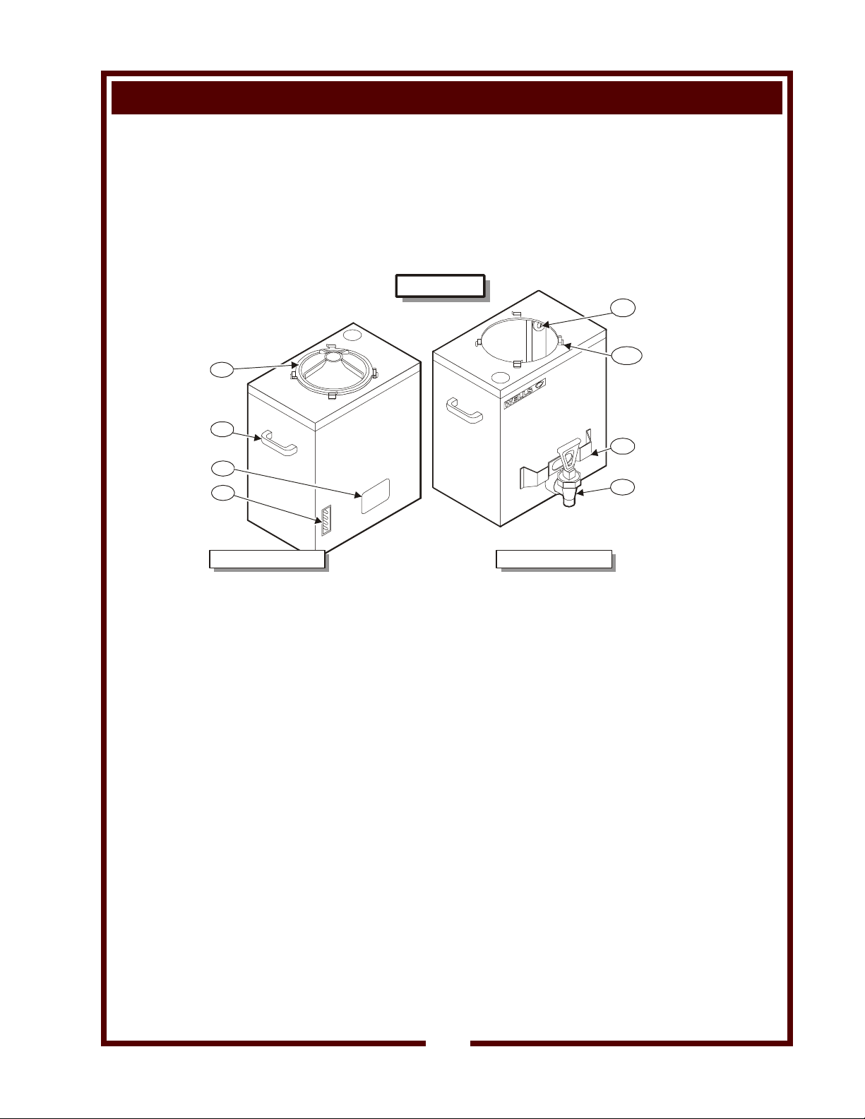
78. VIEW PORT
79. DELIMING FITTING
82. STATUS INDICATOR
90. NAMEPLATE
501
509
590
508
Allows digital readout of controller to be observed.
Quick disconnect fitting attaches to deliming solution bottle.
Glows when filling, flashes when controller is in “error” mode.
(Left side) Gives manufacturer information; lists model no., serial no.
and electrical specifications.
TANK ASSY
520
500a
504
507
Fig. 2 Features & Operating Controls - Water Max™ 5 Gallon Tank
500a. LID HOLDING CLIPS
501. TANK LID
504. FAUCET PROTECTOR
507. FAUCET ASSEMBLY
508. CONTROL
RECEPTACLE
509. RESERVOIR
CARRYING HANDLE
520. WATER LEVEL SENSOR
590. NAMEPLATE
Ears on LID seat in these clips to secure lid.
Hot water is dispensed into the tank here.
Turns clockwise to latch into HOLDING CLIPS.
Provides some protection for FAUCET from damage.
Controls delivery of hot water to container for food prep, etc.
Allows WATER TANK to connect to Water-Max™.
Also provides connection to power to keep tank contents hot.
Used to position the WATER TANK on Mater-Max™
CAUTION - DO NOT ATTEMPT TO MOVE OR CARRY THE
WATER TANK WHEN IT CONTAINS HOT WATER! SEVERE
BURNS MAY RESULT.
Inside WATER TANK. Senses water level. Gives manufacturer information; lists model no., serial no. and electrical specifications.
FRONT VIEWBACK VIEW
3
PRECAUTIONS AND GENERAL INFORMATION
WARNING:
Electric
Shock hazard
All servicing requiring
access to non-insulated
electrical components
must be performed by a
factory authorized
technician.
DO NOT open any access
panel which requires the
use of tools. Failure to
follow this warning can
result in severe electrical
shock.
CAUTION:
Risk of
Damage
DO NOT connect or
energize this appliance
until all installation
instructions are read and
followed. Damage to the
appliance will result if
these instructions are not
followed.
Water-Max™ hot water dispenser is intended for use in
commercial establishments only.
This dispenser is
preparation of food for human consumption. No other use is
recommended or authorized by the manufacturer or its agents.
Operators of this appliance must be familiar with the appliance use,
limitations and associated restrictions.
Operating instructions,
understood by all persons using or installing this appliance.
Cleanliness of this dispenser is essential to good sanitation. Read and
follow all included cleaning instructions and schedules to ensure the
safety of the food product.
Disconnect this appliance from electrical power before performing any
maintenance or servicing.
DO NOT submerge the dispenser or water tank in water. Do not
splash or pour water on, in or over any controls, control panel or wiring.
The technical content of this manual, including any wiring diagrams,
schematics, parts breakdown illustrations and/or adjustment
procedures, is intended for use by qualified technical personnel.
Any procedure which requires the use of tools must be performed by a
qualified technician.
This manual is considered to be a permanent part of the appliance.
This manual and all supplied instructions, diagrams, schematics, parts
breakdown illustrations, notices and labels must remain with the
appliance if it is sold or moved to another location.
This appliance is made in the USA. Unless otherwise noted, this
appliance has American sizes on all hardware.
designed to dispense hot water used in the
warnings and labels must be read and
E6070
E6070
STD 4
AGENCY LISTING INFORMATION
This appliance conforms to NSF Standard 4 for sanitation only if
installed in accordance with the supplied Installation Instructions.
This appliance is
This appliance is
U Listed under File E6070.
V Listed under File E6070.
4
 Loading...