

Page 1
WELLS BLOOMFIELD, LLC
10 Sunnen Dr., St. Louis, MO 63143
telephone: 800-807-9054
fax: 314-781-2714
www.wells-mfg.com
OWNERS MANUAL
WFPE-68KFC
PRESSURE FRYER
434
UNITED STATES
CANADA
INTERNATIONAL
Includes
INSTALLATION
USE & CARE
SERVICE
WFPE-68KFC
Pressure Fryer
IMPORTANT: DO NOT DISCARD THIS MANUAL
This manual is considered to be part of the appliance and is to be given to the OWNER or
MANAGER of the restaurant, or to the person responsible for TRAINING OPERATORS of
this appliance. Additional manuals are available from your WELLS DEALER.
THIS MANUAL MUST BE READ AND UNDERSTOOD BY ALL PERSONS USING OR
INSTALLING THIS APPLIANCE. Contact your WELLS DEALER if you have any
questions concerning installation, operation or maintenance of this equipment.
p/n 2M-305284 Rev. F M434 091230
Page 2

LIMITED WARRANTY STATEMENT
Unless otherwise specified, all commercial cooking
equipment manufactured by WELLS BLOOMFIELD, LLC is
warranted against defects in materials and workmanship for
a period of one year from the date of original installation or
18 months from the date of shipment from our factory,
whichever comes first, and is for the benefit of the original
purchaser only.
THIS WARRANTY IS THE COMPLETE AND ONLY
WARRANTY, EXPRESSED OR IMPLIED IN LAW OR IN
FACT, INCLUDING BUT NOT LIMITED TO, WARRANTIES
OF MERCHANTABILITY OR FITNESS FOR ANY
PARTICULAR PURPOSE, AND/OR FOR DIRECT,
INDIRECT OR CONSEQUENTIAL DAMAGES IN
CONNECTION WITH WELLS BLOOMFIELD PRODUCTS.
This warranty is void if it is determined that, upon inspection
by an authorized service agency, the equipment has been
modified, misused, misapplied, improperly installed, or
damaged in transit or by fire, flood or act of God. It also
does not apply if the serial nameplate has been removed, or
if service is performed by unauthorized personnel. The
prices charged by Wells Bloomfield for its products are
based upon the limitations in this warranty. Seller’s
obligation under this warranty is limited to the repair of
defects without charge by a Wells Bloomfield factory
authorized service agency or one of its sub-service
agencies. This service will be provided on customer’s
premises for non-portable models. Portable models (a
device with a cord and plug) must be taken or shipped to
the closest authorized service agency, transportation
charges prepaid, for service. In addition to restrictions
contained in this warranty, specific limitations are shown in
the Service Policy and Procedure Guide. Wells Bloomfield
authorized service agencies are located in principal cities.
This warranty is valid in the United States and Canada and
void elsewhere. Please consult your classified telephone
directory, your foodservice equipment dealer or contact:
Service Department, Wells Bloomfield, LLC
10 Sunnen Dr, St. Louis, MO 63143
phone (800) 807-9054 or fax (314) 781-2714
for information and other details concerning warranty.
SERVICE POLICY AND PROCEDURE GUIDE and ADDITIONAL WARRANTY EXCLUSIONS
1. Resetting of safety thermostats, circuit breakers, over
load protectors, and/or fuse replacements are not
covered by this warranty unless warranted conditions
are the cause.
2. All problems due to operation at voltages or phase
other than specified on equipment nameplates are
not covered by this warranty.
Conversion to correct voltage and/or phase must be
the customer’s responsibility.
3. All problems due to electrical connections not made
in accordance with electrical code requirements
and wiring diagrams supplied with the equipment are
not covered by this warranty.
4. Replacement of items subject to normal wear, to
include such items as knobs, light bulbs; and, normal
maintenance functions including adjustments of
thermostats, adjustment of micro switches and
replacement of fuses and indicating lights are not
covered by warranty.
5. Damage to electrical cords and/or plug due to exposure
to excessive heat are not covered by this warranty.
6. Full use, care, and maintenance instructions supplied
with each machine. Noted maintenance and
preventative maintenance items, such as servicing and
cleaning schedules, are customer responsibility. Those
miscellaneous adjustments noted are customer
responsibility. Proper attention to preventative
maintenance and scheduled maintenance procedures
will prolong the life of the appliance.
7. Travel mileage is limited to sixty (60) miles from an
Authorized Service Agency or one of its sub-service
agencies.
8. All labor shall be performed during regular working
hours. Overtime premium will be charged to the buyer.
9. All genuine Wells replacement parts are warranted for
ninety (90) days from date of purchase on nonwarranty equipment. This parts warranty is limited only
to replacement of the defective part(s). Any use of
non-genuine Wells parts completely voids any
warranty.
10. Installation, labor, and job check-outs are not
considered warranty and are thus not covered by this
warranty.
11. Charges incurred by delays, waiting time or operating
restrictions that hinder the service technician’s ability to
perform service are not covered by warranty. This
includes institutional and correctional facilities.
434 305284 Owners Manual WFPE-68KFC
SHIPPING DAMAGE CLAIM PROCEDURE
NOTE: For your protection, please note that equipment in
this shipment was carefully inspected and packaged by
skilled personnel before leaving the factory. Upon
acceptance of this shipment, the transportation company
assumes full responsibility for its safe delivery.
IF SHIPMENT ARRIVES DAMAGED:
1. VISIBLE LOSS OR DAMAGE: Be certain that any
visible loss or damage is noted on the freight bill or
express receipt, and that the note of loss or damage is
signed by the delivery person.
2. FILE CLAIM FOR DAMAGE IMMEDIATELY:
Regardless of the extent of the damage.
3. CONCEALED LOSS OR DAMAGE: if damage is
unnoticed until the merchandise is unpacked, notify the
transportation company or carrier immediately, and file
“CONCEALED DAMAGE” claim with them. This
should be done within fifteen (15) days from the date
the delivery was made to you. Be sure to retain the
container for inspection.
Wells Bloomfield cannot assume liability for damage or loss
incurred in transit. We will, however, at your request, supply
you with the necessary documents to support your claim.
xi
Page 3
TABLE OF CONTENTS
GENERAL
WARRANTY xi
SPECIFICATIONS 1
FEATURES & OPERATING CONTROLS 2
AGENCY LISTING INFORMATION 3
PRECAUTIONS & GENERAL INFORMATION 4
INSTALLATION
UNPACKING, INSPECTION and SET-UP 6
ELECTRICAL INSTALLATION 7
USE AND CARE
FRYER OPERATION 8
CLEANING INSTRUCTIONS 11
SERVICE & REPAIR
TROUBLESHOOTING SUGGESTIONS 16
EXPLODED VIEWS & PARTS LIST 18
WIRING DIAGRAM 20
SERVICING INSTRUCTIONS 23
PARTS & SERVICE INFORMATION 33
CUSTOMER SERVICE DATA 33
Thank you for purchasing this
Wells Bloomfield appliance.
Proper installation, professional
operation and consistent
maintenance of this appliance
will ensure that it gives you the
very best performance and a
long, economical service life.
This manual contains the
information needed to properly
install the fryer, to use and
care for the fryer, and to
service and repair the fryer in a
manner which will ensure its
optimum performance.
GENERAL
SPECIFICATIONS
MODEL
VOLTS
50/60 Hz
WATTS
208V 3ø 10,500 29 29 29 n/a n/a
WFPE-68KFC
240V
1ø or 3ø
380-415V
3ø
10,500 25 25 25 n/a 44
10,500 14.6 14.6 14.6 0 n/a
IMPORTANT: This appliance must be installed in compliance with all applicable federal, state and
local codes and ordinances.
Height: 38" (top of work surface)
47" (overall)
434 305284 Owners Manual WFPE-68KFC
52-1/2" (top of operating lever swing)
Width: 20"
Depth: 33"
35-1/4" (including operating lever)
AMPS 3ø
L1 L2 L3 N
ELECTRICAL
DIMENSIONS
AMPS
1ø
POWER SUPPLY
REQUIREMENTS
3-WIRE (L1, L2, L3) plus GND
Dedicated 50 amp 3ø circuit
8 ga. copper min. 90ºC
3 NAC
(L1, L2, L3, N) plus GND
Dedicated 25 amp 3ø circuit
1.5 mm
2
copper min. 90ºC
1
Page 4
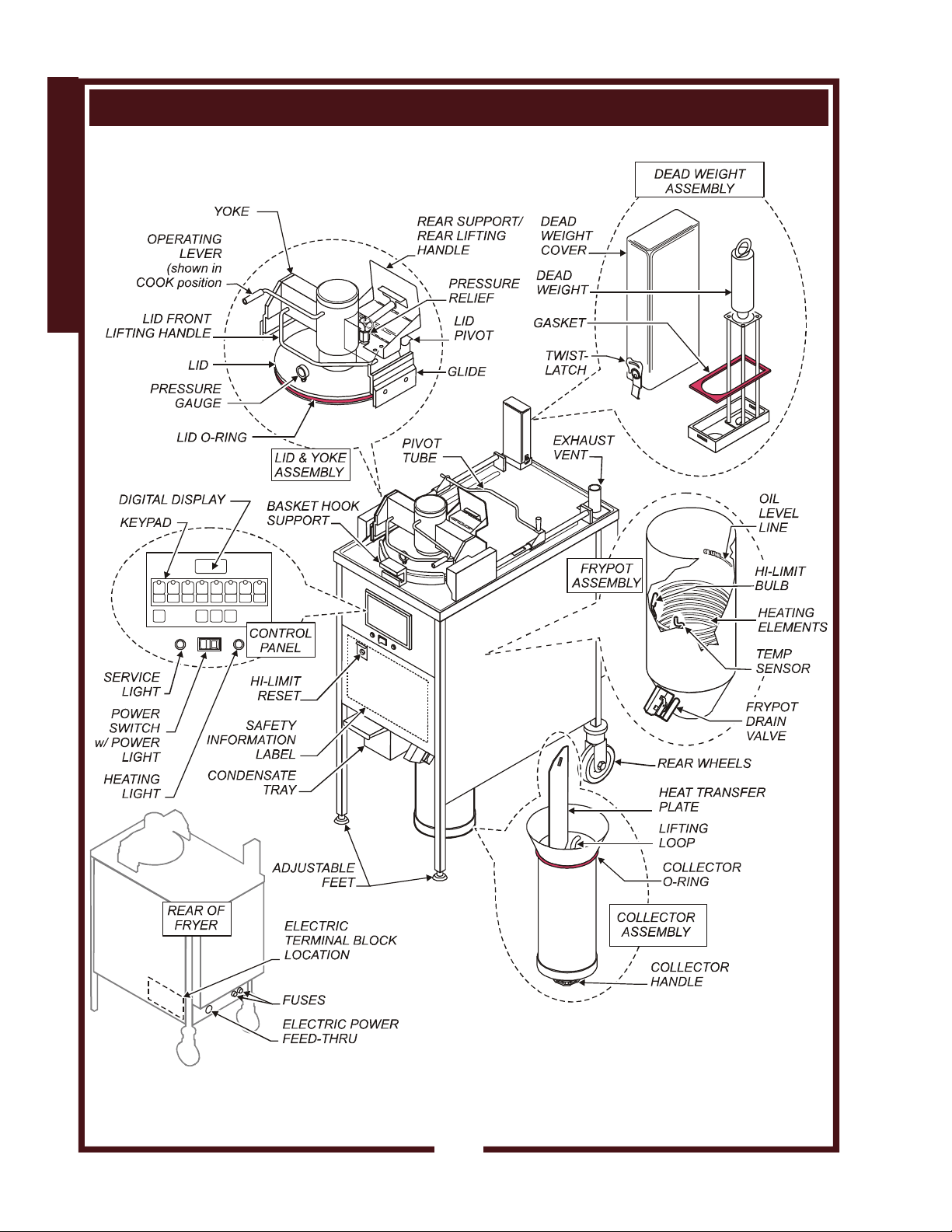
FEATURES & OPERATING CONTROLS
GENERAL
Fig. 1 Features and Operating Controls
434 305284 Owners Manual WFPE-68KFC
2
Page 5
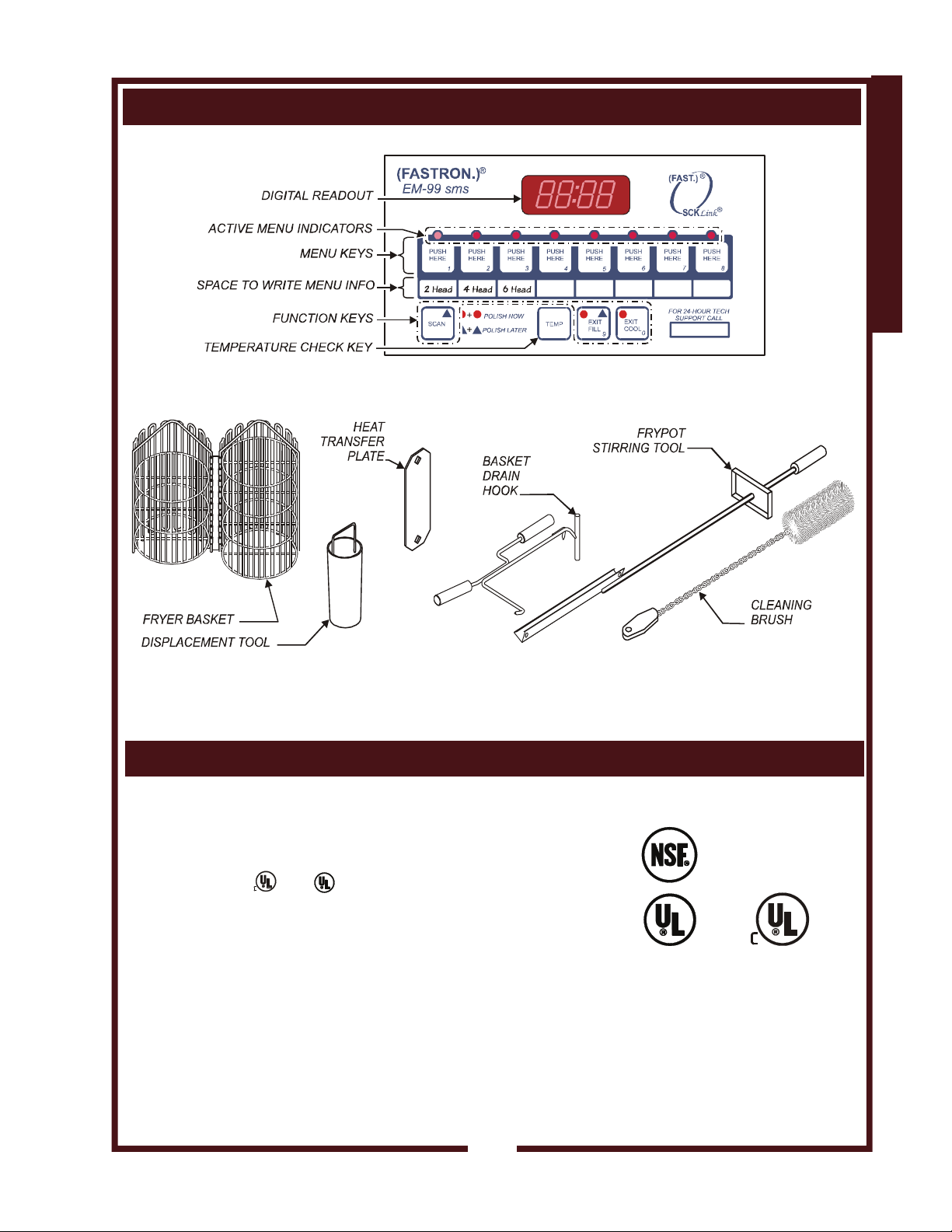
Fig. 2 Electronic Controller
FEATURES & OPERATING CONTROLS (continued)
GENERAL
Fig. 3 Accessories and Tools
This appliance conforms to NSF Standard 4 for sanitation only if
installed in accordance with the supplied Installation Instructions.
This appliance is
434 305284 Owners Manual WFPE-68KFC
and Listed under E6070.
AGENCY LISTING INFORMATION
STD 4
E6070 E6070
3
Page 6
PRECAUTIONS AND GENERAL INFORMATION
GENERAL
DANGER:
BURN
Contact with hot shortening
will cause severe injury or
death. Wear protective
gloves and clothing when
operating or servicing this
fryer.
HAZARD
DANGER:
BURN
Do not attempt to open the
fryer lid until the pressure in
the frypot has fallen to zero.
Opening the lid prematurely
will result in the explosive
release of hot shortening.
Contact with hot shortening
will cause severe injury or
death.
HAZARD
DANGER:
BURN
Do not attempt to open the
fryer drain valve if the frypot
is under pressure.
Opening the drain valve under
pressure will result in the
explosive release of hot
shortening.
Contact with hot shortening
will cause severe injury or
death.
HAZARD
DANGER:
EXPLOSION
Failure to operate this
pressure fryer as described
in this manual can lead to
explosion, severe injury and/
or death.
HAZARD
SAFE OPERATION OF THE PRESSURE FRYER
Contact with hot shortening will cause severe injury to unprotected skin
and eyes. Extensive exposure to hot shortening can cause death.
Protect yourself from contact with hot shortening:
ALWAYS wear protective clothing when operating this pressure
fryer.
ALWAYS wear protective goggles, gloves and apron when
cleaning or servicing this pressure fryer.
Shortening under pressure can be very hazardous unless handled
properly:
DO NOT attempt to operate this fryer without the LID O-RING and
COLLECTOR O-RING properly installed.
Do not operate this fryer if either of the LID O-RING or
COLLECTOR O-RING are damaged. A damaged O-ring will lead
to shortening leaks and/or spraying shortening.
Be sure the LID is seated in the frypot and the OPERATING
LEVER is turned fully COUNTERCLOCKWISE before starting a
cook cycle.
DO NOT attempt to turn the OPERATING LEVER until the
pressure in the frypot has fallen to zero.
DO NOT open the drain valve if the frypot is under pressure.
Opening the lid or drain valve with the fryer under pressure will
result in the explosive release of hot shortening.
Spilled shortening will cause a slip and fall hazard:
Add shortening, replenish the shortening, and service the fryer
carefully to avoid spills.
Clean up shortening spills promptly to avoid creating a slip and fall
hazard.
DO NOT allow water to contaminate the shortening. Water will
boil violently on contact with hot shortening, causing the hot
shortening to splatter.
DO NOT heat water in the fryer
DO NOT use boil-out method to clean the frypot.
DO NOT clean the frypot with water, water spray or steam
spray.
DO NOT use steel wool to clean any part of the fryer.
434 305284 Owners Manual WFPE-68KFC
4
Page 7
PRECAUTIONS AND GENERAL INFORMATION (continued)
WFPE-68KFC Pressure Fryer is intended for use in commercial
establishments only.
This fryer is
other use is
agents.
Operators of this fryer must be thoroughly trained in the appliance use,
precautions, limitations and associated restrictions.
Operating instructions, warnings and labels must be read and
understood by all persons using or installing this appliance.
Cleanliness of this fryer is essential to good sanitation. Read and
follow all included cleaning instructions and schedules to ensure the
safety of the food product.
DO NOT operate the fryer with faulty, loose or missing components.
DO NOT operate this fryer if the control panel is torn or damaged.
Contact a Wells Authorized Service Agent for repairs.
Disconnect this appliance from electrical power before performing any
maintenance or servicing.
DO NOT pour water on, into or over any control, control panel or
wiring.
DO NOT store flammable or combustible items (mops, paper, rags or
chemicals) in, on or near the fryer.
This appliance is not jet-stream approved. Do not direct any water or
steam jet at any part of this appliance. Do not use a jet stream to wash
under the appliance.
The fryer is NOT a ladder. Never stand on the fryer to clean hood
filters. Pull the fryer away from the wall and use a step stool or ladder.
DO NOT stand on, sit on or lean on the fryer.
DO NOT allow foreign objects such as closed containers, cigarette
lighters or aerosol cans near the fryer or hot shortening. If dropped in
hot shortening, such objects may explode.
DO NOT allow any foreign object near the fryer that can fall into the
frypot and cause splashing or splattering of hot shortening.
Any procedure which requires the use of tools must be performed by
a qualified technician.
This manual is considered to be a permanent part of the appliance.
This manual and all supplied instructions, diagrams, schematics, parts
breakdown illustrations, notices and labels must remain with the
appliance if it is sold or moved to another location.
434 305284 Owners Manual WFPE-68KFC
This appliance is made in the USA. Unless otherwise noted, this
appliance has American sizes on all hardware.
designed to prepare food for human consumption. No
recommended or authorized by the manufacturer or its
WARNING:
BURN HAZARD
Do not attempt to operate this
fryer without the LID O-RING
and COLLECTOR O-RING
properly installed.
Do not operate this fryer if the
LID O-RING or COLLECTOR
O-RING are damaged.
Hot oil may be released.
WARNING:
SHOCK HAZARD
All servicing requiring
access to non-insulated
electrical components must
be performed by a factory
authorized technician.
Do not open any access
panel which requires the use
of tools. Failure to follow this
warning can result in severe
electrical shock.
CAUTION:
RISK OF
DAMAGE
DO NOT connect or energize
this appliance until all
installation instructions are
read and followed. Damage
to the appliance will result if
these instructions are not
followed.
IMPORTANT:
The technical content of
this manual, including
any troubleshooting
suggestions, parts breakdown illustrations, wiring
diagrams, schematics,
servicing instructions and/
or adjustment procedures,
is intended for use by
qualified technical
personnel only.
GENERAL
5
Page 8
INSTALLATION
NOTE: DO NOT discard
the carton or other packing
materials until you have
inspected the appliance for
hidden damage and tested it
for proper operation.
Refer to SHIPPING DAMAGE
CLAIM PROCEDURE on the
inside front cover of this
manual.
WARNING:
INSTALLATION
Installation procedures must
be performed by a qualified
technician with full knowledge
of all applicable electrical
codes. Failure can result in
personal injury and property
damage.
RISK OF INJURY
UNPACKING & INSPECTION
Carefully remove the appliance from the carton. Remove all protective
plastic film, packing materials and accessories from the appliance
before connecting electrical power or otherwise performing any
installation procedure.
Carefully read all instructions in this manual and the Installation
Instruction Sheet packed with the appliance before starting any
installation.
Read all instructions in this manual carefully before starting installation
of this fryer. READ AND UNDERSTAND ALL LABELS AND
DIAGRAMS ATTACHED TO THE FRYER.
Carefully account for all components and accessories before
discarding packing materials.
1 ea Fryer Basket
1 ea Condensate Tray
1 ea Basket Drain Hook/Collector Lifting Tool
1 ea Frypot Stirring Tool
1 ea Collector
1 ea Displacement Tool
1 ea Cleaning Brush
2 ea Lid O-Ring
2 ea Collector O-Ring
1 ea Heat Transfer Plate
Store these components in a convenient place for later use:
SETUP
Verify that this fryer installation is in compliance with the specifications
listed in this manual and with local code requirements. THIS IS THE
RESPONSIBILITY OF THE INSTALLER.
Setup the fryer only on a firm, level, non-combustible surface. Verify
local codes for requirements. Concrete, tile, terrazzo or metal surfaces
are recommended. Metal over combustible material may not meet
code for non-combustible surfaces.
Verify that the unit sits firmly ON BOTH LEGS AND BOTH WHEELS.
With a spirit level, check that the appliance is level front-to-back and
side-to-side. With the adjustable legs, adjust as required to level the
appliance. Both legs must be adjusted to firmly contact the floor in
order to prevent tipping.
Some locations require the fryer to be secured to prevent tipping or
rolling. It is the responsibility of the installer to meet this requirement.
DO NOT store flammable or combustible items (mops, paper, rags or
chemicals) in, on or near the fryer.
434 305284 Owners Manual WFPE-68KFC
6
Page 9
INSTALLATION (continued)
ELECTRICAL INSTALLATION
Refer to the nameplate on the appliance to verify the ELECTRICAL
SERVICE POWER. Voltage and phase must match the nameplate
specifications, and available electrical service amperage must meet or
exceed the specifications listed on page 1. Incoming wiring must
comply with National Electrical Code or International specifications.
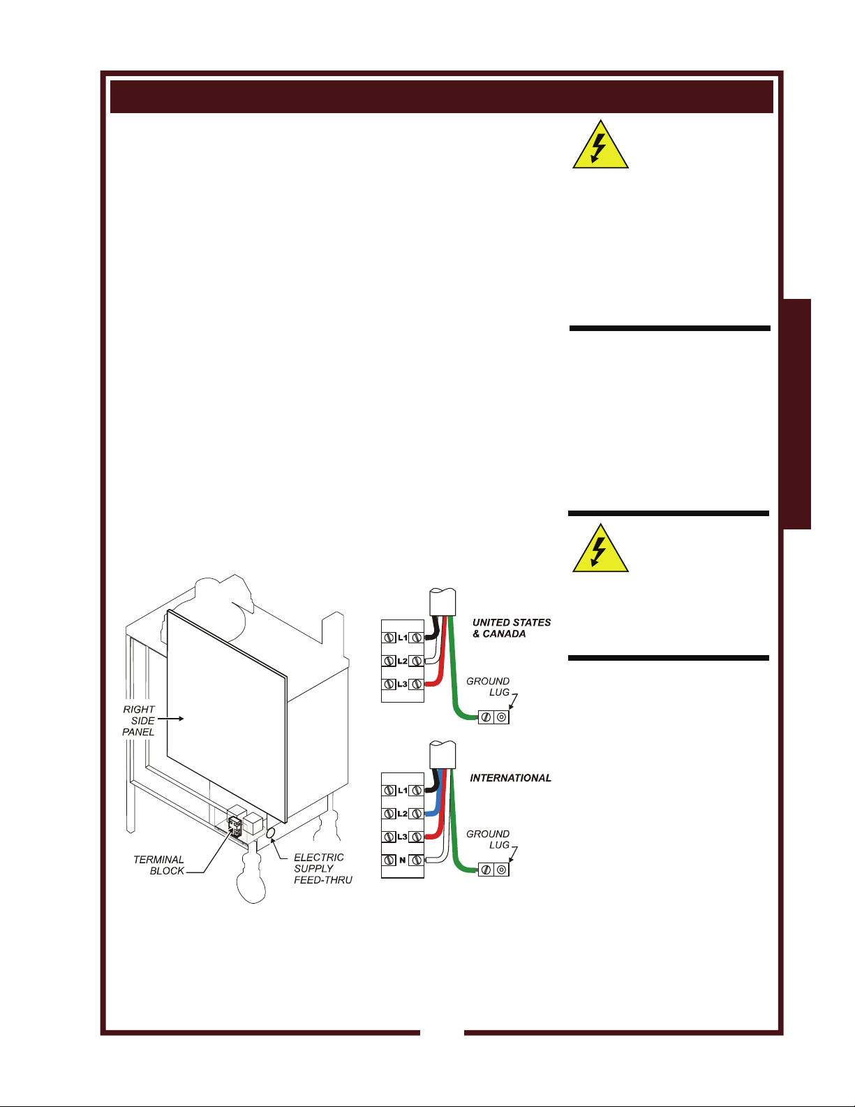
UNITED STATES & CANADA
This appliance requires a dedicated 50 amp, 3-phase circuit. Wiring
must be at least 8 ga. copper suitable for a minimum of 90ºC. Wiring
must be installed with a suitable strain relief (provided by electrical
contactor).
INTERNATIONAL
This appliance requires a dedicated 25 amp, 3-phase circuit (L1, L2,
L3, N plus ground). Wiring must be at least 1.5 mm
a minimum of 90ºC. Wiring must be installed with a suitable strain
relief (provided by electrical contactor).
Remove the RIGHT SIDE PANEL. Route supply wiring from the
FEED-THRU on the lower rear panel, then to the terminal block.
Incoming electrical supply is connected to the L1, L2 and L3 (and N for
international) terminals of the TERMINAL BLOCK.
The chassis-mounted GROUND LUG must be connected to earth
ground.
Verify that all connections are tight.
2
copper suitable for
CAUTION:
SHOCK HAZARD
Removal of any exterior panel
will result in exposed electrical
circuits. Electrical connection
must be performed by a
qualified technician only.
Use care whenever working
around exposed electrical
circuits.
IMPORTANT:
Contact a licensed electrician
to install and connect
electrical power to the
fryer.
IMPORTANT:
Damage due to being
connected to the wrong
voltage or phase is NOT
covered by warranty.
CAUTION:
SHOCK HAZARD
Failure to connect the chassis
ground to a suitable earth
ground will result in a potential
shock hazard.
INSTALLATION
434 305284 Owners Manual WFPE-68KFC
Fig. 4 Terminal Block Location and Wiring
7
Page 10
OPERATION
DANGER:
BURN
Contact with hot shortening
will cause severe injury or
death. Wear protective
gloves and clothing when
operating this fryer.
HAZARD
CAUTION
SHOCK HAZARD
If you experience an electrical
shock from the fryer:
IMMEDIATELY disconnect
the fryer at the circuit breaker
and contact an
AUTHORIZED WELLS
SERVICE AGENT for repairs.
USE AND CARE
GENERAL GUIDELINES
ALWAYS be sure the
pressure gauge reads "0"
before turning the operating
lever clockwise.
ALWAYS be sure the
LID O-RING is in good
condition and properly
installed.
*IMPORTANT:
Collector MUST be Wellstype collector with collapsible
handle welded to the bottom.
ALWAYS be sure the
COLLECTOR O-RING is in
good condition and properly
installed.
DAILY START-UP
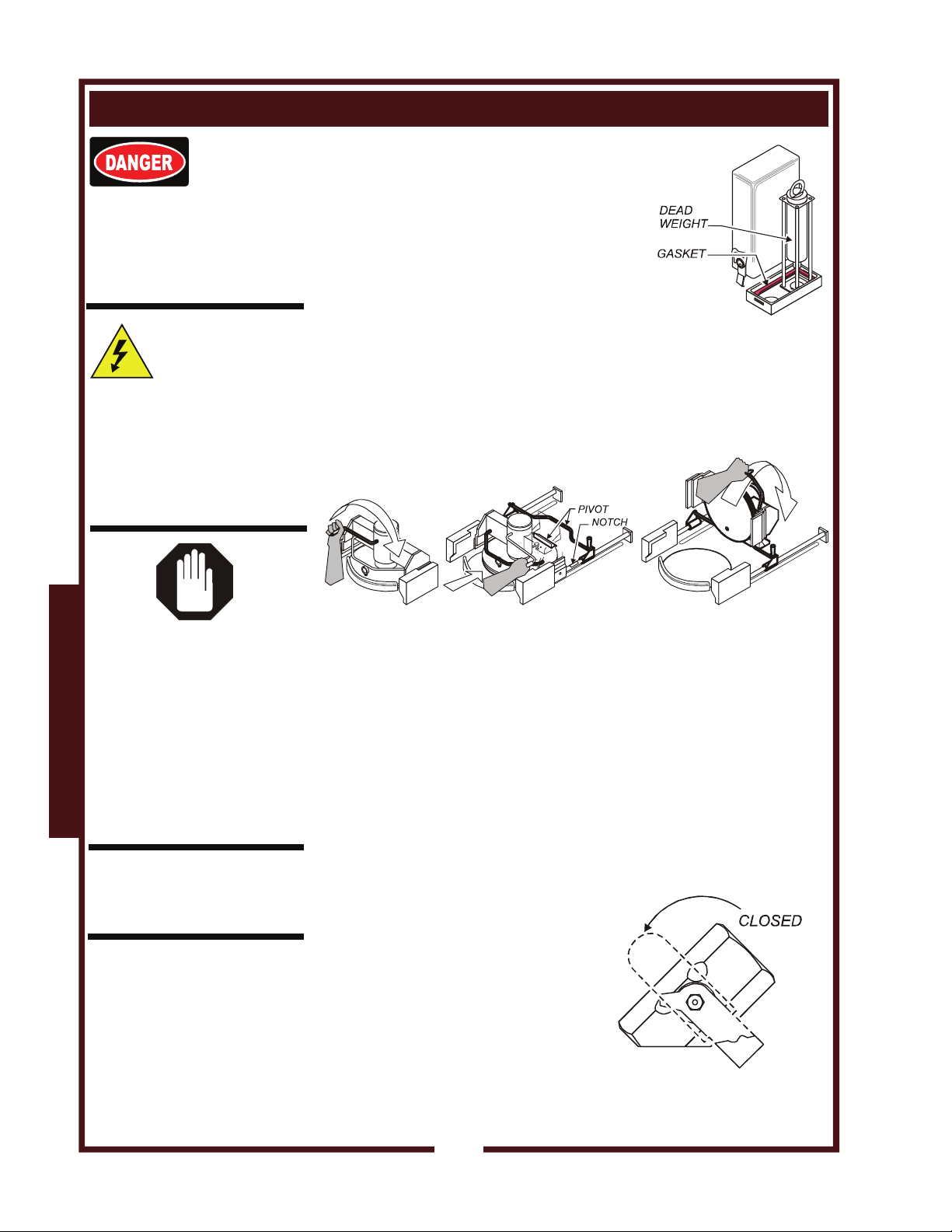
Remove the DEAD WEIGHT COVER.
Verify that the DEAD WEIGHT is in place
and that the vent holes are clean and free
from obstructions. Be sure the gasket is in
position, then latch the cover in place.
Be sure the EXHAUST VENT is free from
obstructions.
Open the FRYPOT LID. Turn the operating lever fully clockwise.
Slide pivot tube forward until it drops into the indents in the rods.
Slide the lid and yoke assembly to the rear until the lid pivot is in
the pivot tube.
Using the LID HANDLE, lift the front of the lid and yoke until it
rests on the REAR SUPPORT in the raised position.
Lubricate a freshly cleaned LID O-RING with a thin coating of
vegetable oil, then install the o-ring in the groove in the lid. Set the
lid and yoke assembly back onto the glides.
Lift the pivot tube slightly and slide it to the rear of the fryer.
Be sure the frypot is clean, and all breading and crumbs have been
brushed from between the heating elements.
Lubricate a freshly cleaned COLLECTOR O-RING with a thin
coating of vegetable oil, then install the o-ring in the groove in the
COLLECTOR*. Fully insert the COLLECTOR ASSEMBLY into the
opening in the bottom of the FRYPOT. DO NOT install the HEAT
TRANSFER PLATE at this time.
Check the DRAIN VALVE.
Make sure the valve is fully
closed.
Be sure the CONDENSATE TRAY
is empty and properly installed.
434 305284 Owners Manual WFPE-68KFC
8
Page 11
OPERATION (continued)
ADD SHORTENING
Pack 68 lbs (31 kg) of solid shortening into the
frypot. If using liquid shortening, fill frypot to
LOWER OIL LEVEL line. Be sure the heating
elements are completely covered with shortening.
Connect the fryer to electric power by turning on
the circuit breaker. Press the POWER SWITCH
ON. The POWER LIGHT will glow.
Press EXIT COOL, then press 2, 4 or 6-head
MENU KEY (first product to be cooked) The
digital readout will display "LO" while the fryer is
in the shortening melt cycle.
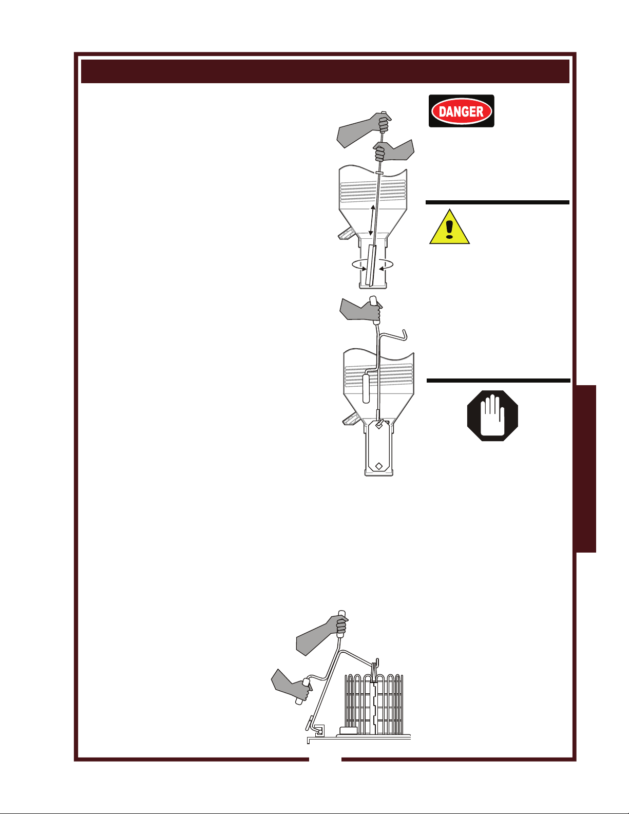
With the FRYPOT STIRRING TOOL, stir the
shortening. Push the stirring tool through the
shortening to the bottom of the collector as the
shortening heats, until all shortening is melted.
Be sure the heating elements are covered with
shortening at all times. Stir until all shortening
is melted.
All shortening in the collector must be completely
melted. Stir into the collector until all shortening is
visibly melted, and at least 5 minutes thereafter.
Using the hook of the BASKET/COLLECTOR
REMOVAL TOOL, lower the HEAT TRANSFER
PLATE into the bottom of the collector.
When the digital readout displays droP, and the
HEAT LIGHT begins to cycle, check the shortening level.
The level must be up to the UPPER OIL LEVEL line scribed into
the frypot above the elements.
Add shortening if necessary.
If overfilled, dip out excess shortening using a saucepan. Use
the excess shortening later as add-back.
Stir the shortening in the frypot thoroughly at least once before
cooking. Do not stir the collector once the heat transfer plate is in
place.
LOAD FRYER BASKET
434 305284 Owners Manual WFPE-68KFC
Using established procedures,
load the FRYER BASKET.
Suspend the fryer basket over the
frypot using the BASKET DRAIN
HOOK.
DANGER:
BURN
Contact with hot shortening
will cause severe injury or
death. Wear protective
gloves and clothing when
operating this fryer.
HAZARD
CAUTION:
FIRE HAZARD,
EQUIPMENT
DAMAGE
The heating elements must
be covered with shortening
before the fryer is energized,
and at all times during the
shortening
operation.
damage and possible fire will
result if the elements are
dry-fired.
GENERAL GUIDELINES
ALWAYS be sure the drain
valve is closed before filling
the frypot.
ALWAYS check the fryer
leveling before operating.
Shortening should be at the
same distance from the rim
all the way around the frypot.
ALWAYS use the basket
drain hook to raise / lower the
fryer basket into / out of the
frypot.
ALWAYS use two hands to
manipulate the drain hook.
melt cycle and fryer
Serious equipment
USE AND CARE
9
Page 12

OPERATION (continued)
DANGER:
BURN
Contact with hot shortening
will cause severe injury or
death. Wear protective
gloves and clothing when
operating this fryer.
HAZARD
CAUTION:
FIRE HAZARD
EQUIPMENT
The heating elements must
be covered with shortening
before the fryer is energized,
and at all times during the
shortening
operation.
damage and possible fire will
result if the elements are dryfired.
To cancel a cook cycle, press
and hold the active menu key
for 3 seconds.
USE AND CARE
ALWAYS be sure the lid
o-ring is in place before
closing the frypot cover.
ALWAYS be sure the
operating lever is turned fully
counterclockwise before
starting a cook cycle.
ALWAYS be sure the
pressure gauge reads "0"
before turning the operating
lever clockwise.
ALWAYS use the basket
drain hook to raise / lower the
fryer basket into / out of the
frypot.
ALWAYS use two hands to
manipulate the drain hook.
DAMAGE
melt cycle and fryer
Serious equipment
GENERAL GUIDELINES
FRYER OPERATION
Press the EXIT COOL key. When the digital readout displays
droP, lower the fryer basket into the frypot. Lower slowly to avoid
foaming. Remove and properly store the drain hook.
Slide the lid and yoke forward. When it is over the frypot, turn the
operating lever fully counterclockwise. This lowers the lid into the
frypot.
Press the desired menu (2, 4 or 6 head) key. The active menu
indicator will glow. And the timer will count down the cook time.
While there is pressure in the frypot, the operating lever is locked in
the down position.
Pressure will build during the cook cycle. At the end of the cook
cycle, pressure in the frypot is released, the audible signal sounds,
and the digital display reads donE.
When the pressure gauge drops to zero, raise the lid by turning the
operating lever counterclockwise (which releases the lid lock), then
fully clockwise to raise the lid.
Slide the lid and yoke assembly toward the rear until it clears the
frypot. Using the basket drain hook, lift the fryer basket out of the
frypot and hook on the front edge of the fryer frame. Suspend the
fryer basket over the frypot to drain.
Once drained, remove basket with drain hook. Product is ready for
any additional processing prior to serving.
434 305284 Owners Manual WFPE-68KFC
10
Page 13

CLEANING INSTRUCTIONS
PROCEDURE: Cleaning During Operation
PRECAUTIONS: Wear protective goggles, gloves, and apron
FREQUENCY: As required, approximately every 3 - 6 loads
TOOLS: Frypot Stirring Tool
Hi-Temperature Brush
Breading will build up at the oil line. This breading must be removed
from the cooking zone to prevent leaving burned specks on product.
Also, the elements must be kept free of breading crumbs and other
cooking debris to ensure optimum operation.
1. Remove the fryer basket from the fryer. Using the blade of the
FRYPOT STIRRING TOOL, scrape the built-up breading from the
oil line.
2. Using a hi-temperature brush, brush all breading and other cooking
debris from the face of the heating elements, and from between the
elements, element retainers and the frypot.
IMPORTANT: Be careful when cleaning around the temperature
probe and hi-limit thermobulb. Damage to either component will
put the fryer out of service.
3. Using a hi-temperature brush, push all breading and crumb s into
the collector.
4. Check the shortening level. Add shortening as required to bring the
level between the MIN OIL and MAX OIL lines.
5. Using the FRYPOT STIRRING TOOL, stir the frypot until all
shortening is melted. DO NOT stir into the collector.
6. Raise LID AND YOKE assembly (see page 8). Clean bottom of lid
then carefully return lid & yoke to horizontal position.
7. Check CONDENSATE TRAY. Empty if necessary and reinstall.
434 305284 Owners Manual WFPE-68KFC
8. Properly store tools.
Procedure is complete
DANGER:
BURN
Contact with hot shortening
will cause severe injury or
death. Wear protective
gloves and clothing when
cleaning this fryer during
operation.
Clean Breading from Oil Line
Clean Heating Elements
HAZARD
USE AND CARE
11
Page 14

CLEANING INSTRUCTIONS (continued)
DANGER:
BURN
HAZARD
Contact with hot shortening
will cause severe injury or
death. Wear protective
gloves and clothing when
changing shortening.
FRYER MUST NOT BE
PRESSURIZED WHEN
PERFORMING THIS
PROCEDURE
CAUTION:
BURN HAZARD
Open the valve slowly to
avoid splashing hot
shortening.
CAUTION:
BURN HAZARD
The drained shortening and
the container are hot and can
cause burns.
USE AND CARE
CAUTION:
SLIPPING
Avoid spilling shortening on
the floor. Clean up all spills
immediately to prevent
creating a slip and fall
hazard.
IMPORTANT:
The displacement tool is to
be used to force shortening
up to the drain opening.
DO NOT use the
displacement tool to bail or
transport shortening.
HAZARD
PROCEDURE: Drain or Replace Shortening
PRECAUTIONS: Disconnect fryer from electric power
Wear protective goggles, gloves, and apron
FREQUENCY: As required, shortening to be filtered or replaced
TOOLS: Basket / Collector Tool, Displacement Tool
Container for Shortening
1. Disconnect fryer from electric power.
Frypot lid must be in the open position.
Remove fryer basket from fryer.
2. Position an appropriate container or
approved shortening filtration system
under the drain valve. Open the drain
valve and drain frypot shortening into
the container.
3. Using the BASKET / COLLECTOR TOOL, remove the HEAT
TRANSFER PLATE from the COLLECTOR.
4. Using the DISPLACEMENT TOOL, force as much shortening as
possible to drain into the container.
Follow established procedures for handling used shortening.
Empty the collector (see page 13), or clean the fryer (see page 13).
Procedure is complete
434 305284 Owners Manual WFPE-68KFC
12
Page 15

CLEANING INSTRUCTIONS (continued)
PROCEDURE: Daily Cleaning
PRECAUTIONS: Disconnect fryer from electric power
Drain shortening. Allow fryer to cool
Wear protective goggles, gloves, and apron
FREQUENCY: Daily
TOOLS: Basket / Collector Tool, Frypot Stirring Tool,
Clean Cloth or Sponge, Nylon Brush
1. Disconnect fryer from electric power. Remove fryer basket from
fryer. Drain shortening (see page 12).
2. Using the BASKET / COLLECTOR TOOL, lift the
COLLECTOR from the frypot. Empty collector
contents per established procedures. Hold the
collector by the HANDLE on the bottom when
emptying.
3. Place a stockpot under frypot to catch all
breading and oil drips. Using a nylon brush, clean
all breading and crumbs from frypot.
4. Clean components by wiping with a clean cloth:
DO NOT use caustic cleaners.
DO NOT use steel wool.
DO NOT use soap.
DO NOT spray with water or steam.
Raise LID AND YOKE assembly (see page 8).
Carefully remove LID O-RING, then turn OPERATING LEVER
fully counterclockwise. Clean lid and yoke. Install a freshly
cleaned o-ring before operating fryer. Turn operating lever fully
clockwise.
Clean cabinet and counter top. Do not pour water on, into or over
the control panel.
Set yoke and lid assembly back into the horizontal position.
Disassemble DEAD WEIGHT ASSEMBLY (see page 8). Clean all
internal components, then reassemble.
Remove COLLECTOR O-RING from COLLECTOR. Clean
collector. Install a freshly cleaned o-ring. Set collector back into
frypot.
Empty and clean CONDENSATE TRAY. Reinstall in fryer.
434 305284 Owners Manual WFPE-68KFC
Clean HEAT TRANSFER PLATE. Set aside.
Clean fryer baskets, brushes, collector lifting tool, frypot stirring tool
and displacement tool.
Clean lid and collector o-rings. Store o-rings in a shallow pan of
water in a refrigerator until ready for the next use cycle.
5. Close lid. Properly store tools.
Procedure is complete
DANGER:
BURN
HAZARD
Contact with hot shortening
will cause severe injury or
death. Wear protective
gloves and clothing when
cleaning this fryer during
operation.
CAUTION:
SLIPPING
HAZARD
Avoid spilling shortening on
the floor. Clean up all spills
immediately to prevent
creating a slip and fall
hazard.
CAUTION:
HOT OIL
SPLATTER
HAZARD
DO NOT clean the frypot with
commercial boil-out products.
DO NOT clean with water or
steam spray. Water will boil
violently causing splatter
when the shortening reaches
temperature.
IMPORTANT:
Clean components with a
clean towel or sponge Scrub
with a soft bristle brush only if
necessary to remove food
particles.
NOTE: The following may
safely be cleaned in a
dishwasher:
Collector, heat transfer plate,
fryer basket, condensate tray,
tools.
IMPORTANT:
Be sure all components are
completely dry. Water will
boil violently on contact with
hot oil, causing hot oil to
splatter.
USE AND CARE
13
Page 16

CLEANING INSTRUCTIONS (continued)
DANGER:
BURN
Contact with hot shortening
will cause severe injury or
death. Wear protective
gloves and clothing when
cleaning this fryer during
operation.
HAZARD
CAUTION:
HOT OIL
SPLATTERING
HAZARD
DO NOT use water to clean
lid. Water can contaminate
the shortening, causing
violent splattering of hot oil.
IMPORTANT:
Yoke and lid assembly
weighs approximately 70 lbs.
Use appropriate lifting
procedures.
IMPORTANT:
USE AND CARE
Clean components with a
clean towel or sponge Scrub
with a soft bristle brush only if
necessary to remove food
particles.
PROCEDURE: Clean Lid and Yoke Assembly
PRECAUTIONS: Wear protective gloves and apron
Lid Assembly is heavy! Use caution lifting.
FREQUENCY: Weekly or As Needed
TOOLS: Clean Towels or Sponge, Soft Bristle Brush
1. Open the FRYPOT LID. Turn the operating lever fully clockwise.
Slide pivot tube forward until it drops into the indents in the rods.
Slide the lid and yoke assembly to the rear until the lid pivots in the
pivot tube.
Using the LID HANDLE, lift the front of the lid and yoke until it
rests on the REAR SUPPORT.
2. Remove lid o-ring from groove. Wipe o-ring clean, then store in
water in the refrigerator.
3. Wipe bottom of lid until clean. Be sure o-ring groove is clean and
free from shortening build-up.
4. Lower lid to horizontal position. Slide pivot tube fully to the rear.
5. Turn operating lever fully counterclockwise to raise yoke assembly.
Wipe all components until clean. Be sure area at base of piston is
free from shortening build-up.
6. Turn operating lever fully clockwise. Raise lid to vertical position as
in step 1.
7. Lubricate fresh lid o-ring with clean vegetable oil and install in lid
o-ring groove. Lower lid to horizontal position. Slide pivot tube fully
to the rear.
Procedure is complete
434 305284 Owners Manual WFPE-68KFC
14
Page 17

CLEANING INSTRUCTIONS (continued)
PROCEDURE: Clean Pivot Tube and Slide Rods
PRECAUTIONS: Wear protective gloves and apron
FREQUENCY: Monthly or As Needed
TOOLS: Clean Towels or sponge, Bottle Brush
Flat Blade Screwdriver
1. Lower lid into the frypot. Unlatch and remove dead weight cover.
2. Loosen screws in right and left rod mounting blocks. Work slide
rods to the rear until they are clear of the front mounting blocks.
3. Free pivot tube from slide rods. Pivot tube may be cleaned in the
dishwasher. Use a bottle brush to clean the inside of the pivot tube
guides.
4.
Work slide rods out of the rod mounting blocks. Slide rods may be
cleaned in the dishwasher. Scrub with a soft bristle brush only if
necessary to remove food particles from indents.
5. Reinsert slide rods into mounting blocks. Install pivot tube on slide
rods.
6. Reinstall slide rods in front mounting blocks. Tighten screws in rod
mounting blocks. Test pivot rod for proper operation.
Procedure is complete
DANGER:
BURN
Contact with hot shortening
will cause severe injury or
death. Wear protective
gloves and clothing when
cleaning this fryer during
operation.
NOTE: The following may
safely be cleaned in the
dishwasher:
Pivot Tube
Slide Rods
IMPORTANT:
Be sure all components are
completely dry before
reinstalling. Water will boil
violently on contact with hot
oil, causing hot oil to splatter.
SUGGESTION:
When reinstalling, engage
pivot tube guides in slide rod
indents prior to tightening
screws in order to ensure
proper alignment.
HAZARD
USE AND CARE
434 305284 Owners Manual WFPE-68KFC
15
Page 18

These troubleshooting suggestions are intended for use by qualified technical personnel only.
TROUBLESHOOTING SUGGESTIONS
Problem Possible Cause Suggested Remedy
No power to fryer Fryer unplugged or circuit breaker off or
tripped
Power switch off or damaged Press power switch to ON
Blown fuse Correct cause of fuse failure
No power -
"service" light lit
Hi-limit safety trips often Thermobulb contaminated with crumbs Clean hi-limit thermobulb
Fryer does not heat
"power" light lit
"heat" light lit
"service" light not lit
Hi-limit safety tripped Allow to cool, reset safety
Temp sensor contaminated with crumbs Clean temperature sensor probe
Temp sensor or wiring damaged Check wiring for damage, repair as req'd.
Hi-limit safety or thermobulb damaged Replace hi-limit safety
24v relay R1 damaged (welded
contacts)
Controller damaged If relay R1 remains energized at all oil temps,
Wiring damage (elements, contactors) Check wiring for damage, repair as req'd.
Damaged E-Safe relay Replace E-Safe relay
Damaged back-up contactor Replace back-up contactor
Connect fryer to power
Reset circuit breaker
Replace power switch
Replace fuse
Replace temperature sensor probe
Replace relay R1
replace controller
Fryer does not heat
"power" light lit
"heat" light not lit
"service" light not lit
Fryer will not build
pressure
SERVICE
Temp sensor or wiring damaged Check wiring for damage, repair as req'd.
Replace temperature sensor probe
Relay R3 or wiring damage Check wiring for damage, repair as req'd.
Replace relay R3
24v relay R1 or wiring damaged Replace relay R1
24v transformer damaged Replace transformer
Controller damaged If no 24v to R1 when calling for heat , replace
controller
Insufficient moisture in product Cook only authorized product
Lid o-ring damaged or missing Replace lid o-ring
Dead weight damaged or dirty Clean dead weight, replace if req'd.
Pressure relief body damaged or dirty Clean pressure relief body, replace if req'd.
Relief pin bent or dirty Clean relief pin, replace as req'd.
Pressure relief valve damaged Replace pressure relief valve
Pressure gauge damaged Replace pressure gauge
Solenoid damaged Replace solenoid
Connecting link or cotter pin damaged Replace connecting link and cotter pins
Pressure hose damaged Replace pressure hose
24V relay R2 or wiring damaged Check wiring for damage, repair as req'd.
Replace relay R1
434 305284 Owners Manual WFPE-68KFC
Controller damaged If no 24v to R2 during pressure phase of cook
cycle, replace controller
16
Page 19

TROUBLESHOOTING SUGGESTIONS (continued)
Problem Possible Cause Suggested Remedy
Fryer slow to heat /
recover
Controller works only
intermittently
Cannot lower lid Pivot tube engaged Be sure pivot tube is disengaged from pivot
Cannot raise lid Pressure not bled off Lid cannot be raised until all pressure has
Heating elements dirty Clean elements and frypot
One or more damaged elements Replace defective heating elements
Insufficient ventilation Be sure area u nder fryer remains clear
Cooling fan damaged or dirty Clean or replace cooling fan
24v transformer damaged Replace transformer
Damaged controller If internal temperature and 24v supply OK,
replace controller. Be sure cooling fan is
operating
bracket at back of lid
Lid not centered over frypot Position lid & yoke properly
Lid o-ring not properly installed Properly install o-ring
Piston and/or yoke damaged or dirty Disassemble, thoroughly clean yoke & lid
Repair or replace as required
been relieved from frypot
Improper procedure for opening After all pressure has been relieved, turn
operating lever fully counterclockwise to
release cam pawl, then fully clockwise to raise
lid.
Lid has cocked in frypot Tap front and back of lid while attempting to
move operating lever both directions
Lid hard to raise or lower Lid o-ring not properly installed Properly install o-ring
Piston and/or yoke damaged or dirty Disassemble, thoroughly clean yoke & lid
Repair or replace as required
Excess water and grease
vented from exhaust
Steam vents from
pressure relief cover
Frypot leaks at collector Collector o-ring missing or damaged Replace o-ring
Fryer basket will not lower
434 305284 Owners Manual WFPE-68KFC
fully into frypot
Muffler full of condensate and
shortening
Latches not properly engaged Engage extended fingers of latches fully in
Gasket missing or damaged Replace gasket
Pressure relief cover damaged Replace pressure reli ef cover
Collector o-ring improperly installed Properly install o-ring
Collector damaged Replace collector
Excessive built up of crumbs in frypot Clean frypot, empty collector
Bracket for hi-limit thermobulb damaged Repair or replace thermobulb bracket.
One or more element clamps damaged Repair or replace element clamps
Remove and clean muffler. Be sure drain line
is clear.
slots, then turn twist latch handle 180º
clockwise
Examine thermobulb for damage.
Examine elements for damage
These troubleshooting suggestions are intended for use by qualified technical person nel only.
SERVICE
No reading or incorrect
reading on pressure
gauge
Gauge orifice dirty Remove gauge and clean
Damaged pressure gauge Replace gauge
17
Page 20

EXPLODED VIEW & PARTS LIST
These parts breakdown drawings are intended for use by qualified technical personnel only.
SERVICE
434 305284 Owners Manual WFPE-68KFC
18
Page 21

WFPE-68KFC EXPLODED VIEW & PARTS LIST (continued)
ITEM PART NO DESCRIPTION ITEM PART NO DESCRIPTION
1 2J-305297 PROBE, TEMPERATURE 47 2C-305361 PIN, RETAINING
2 WS-506379 CLAMP, HI-LIMIT THERMOBULB 48 2V-305388 PIVOT ARM
WS-506130 THERMO, HI-LIMIT SAFETY, (s/n before KFC10170) 49 E7-305236 CONNECTING ROD
4
2T-306470
2N-306149UL ELEMENT, 240V 3500W 51 2E-305798 RELAY, 24V
5
2N-306150UL ELEMENT, 208V 3500W 52 2J-31157 LIGHT, INDICATING RED
6 2D-306167 CLAMP, HEATING ELEMENT 53 2E-305295 SWITCH, 240V DPST LIGHTED
8 2V-306036 VALVE, FRYPOT DRAIN 54 2J-30516 LIGHT, INDICATING AMBER
9
DD-305451 DEAD WEIGHT 11 PSI 56 2E-43880 RELAY, 240V
E7-305433 DEAD WEIGHT 12 PSI 57 2E-Z5741 TRANSFORMER, 208/240—24VAC, 40VA
10 2I-305218 GASKET, DEAD WEIGHT COVER 58 2U-303655 FAN, 240V
11 <305400> ASSEMBLY, DEAD WEIGHT CAGE 59 2A-306161 FOOT ADJUSTABLE
12 E7-505972 SUPPORT BLOCK, BASKET HOOK 60 2P-305419 CASTER NON-SWIVEL
13 E7-305289 COVER, DEAD WEIGHT 61 2E-306967B RELAY, 240V E-SAFE
14 2R-306158 GLIDE, LID
15 DD-305373 PISTON, LID 2E-37780 CONTACTOR 240V
16 2V-305449 GAUGE, PRESSURE 0-15 PSI
17 2L-305406 LID 2E-40310 TERMINAL BLOCK 4P
18 2I-305308 O-RING, LID 64 2D-305413 ASSEMBLY, COLLECTOR
19 2D-306152 CAP, YOKE 65 2I-305309 O-RING, COLLECTOR
20 <305389> CAM PLATE 66 E7-305337 HEAT TRANSFER PLATE
21 <305398> ASSEMBLY, YOKE 67 E7-306079 TRAY, CONDENSATE
22 2R-305192 HANDLE, OPERATING LEVER 71 <306081> ASSEMBLY, ADAPTER, 1/2 MPT x HOSE
23 E7-305366 TUBE, PRESSURE RELIEF VENT 72 2J-306080 FLEX HOSE
24 2V-305306 VALVE, PRESSURE RELIEF 73 2K-306083 ADAPTER, 1/2 FPT x HOSE FLARE
25 2K-305365 ADAPTER, PRESSURE RELIEF VALVE 74 2K-306082 NIPPLE 1/2MPT CLOSE
26 <305203> ASSEMBLY, LID SUPPORT 75 DD-506078 SWITCH GUARD
27 2V-305383 MOUNTING BLOCK, LEFT 80 ASSEMBLY, FRAME
28 2V-305384 MOUNTING BLOCK, RIGHT 81 E7-305231 PANEL, SIDE
29 2A-305382 SLIDE ROD 82 E7-305270 PANEL, FRONT UPPER, CONTROL
30 E7-505439 PIVOT TUBE 83 E7-305212 PANEL, FRONT LOWER
31 E7-505381 MOUNTING BLOCK, ROD 84 E7-305229 PANEL, REAR
32 E7-305254 ASSEMBLY, EXHAUST VENT 85 2I-306183 O-RING, DEAD WEIGHT PIN
33 E7-505307 CLAMP, EXHAUST TUBE 86 E7-305227 SHELF, ELECTRICAL
34 2J-306134 TUBE, EXHAUST MUFFLER INLET 87 2E-34768 FUSE, SC-10 10A 300V (pk 4)
35 2J-306135 TUBE, EXHAUST MUFFLER OUTLET 88 2E-34769 FUSE HOLDER, HPG-EE 10A 240V
36 E7-305174 LID, EXHAUST MUFFLER 90 2D-305378 ASSEMBLY, FRYPOT
37 2I-305425 GASKET, EXHAUST MUFFLER
38 <305178> MUFFLER, EXHAUST WS-23079 BASKET, CHICKEN COOKING 4-HEAD
39 E7-305164 BRACKET, PIVOT T2 2V-305326 TOOL, DISPLACEMENT
434 305284 Owners Manual WFPE-68KFC
40 2C-305362 PIVOT PIN T3 E7-306138
41 505361 CLIP, RETAINING T5 DD-22886 TOOL, STIRRING
42 2E-305387 PIN, PRESSURE RELIEF T6 2P-305355 BRUSH
43 505167 BUSHING
44 E7-305235 COVER, MOUNTING BRACKET
45 2E-305426 SOLENOID, PRESSURE RELIEF
46 E7-305234 BRACKET, SOLENOID MOUNTING
THERMO, HI-LIMIT SAFETY,
(s/n KFC10170 and later)
DEAD WEIGHT 9 PSI 55 2J-305280 CONTROLLER F.A.S. T. EM99
50 2K-48689 STRAIN RELIEF, WATER-TIGHT
2E-37779 CONTACTOR 208V
62
WS-50131 TERMINAL BLOCK 3P
63
DD-22891 BASKET, CHICKEN COOKING 6-HEAD
T1
BASKET DRAIN HOOK/COLL. REMOVAL
TOOL
5E-22943 INCL. ITEMS T2 thru T6
KIT
PART NUMBERS IN <BRACKETS> ARE FOR REFERENCE ONLY
These parts breakdown drawings are intended for use by qualified technical personnel only.
SERVICE
19
Page 22

WIRING DIAGRAM
This wiring diagram is intended for use by qualified technical personnel only.
SERVICE
434 305284 Owners Manual WFPE-68KFC
20
Page 23

WIRING DIAGRAM (continued)
434 305284 Owners Manual WFPE-68KFC
SERVICE
21
Page 24

WIRING DIAGRAM (continued)
This wiring diagram is intended for use by qualified technical personnel only.
SERVICE
434 305284 Owners Manual WFPE-68KFC
22
Page 25

CABINET COMPONENTS
A. Removable Components
The following major components may be removed without the use
of service tools:
Lid and Yoke Assembly
Condensate Tray
Collector and Heat Transfer Plate (use the Collector Lifting Tool)
Dead Weight Cover and Dead Weight
Remove the Muffler by loosening the four hose clamps that secure
the exhaust tubing. Work the tubing off of the vent tubes, then lift
the muffler out of the cabinet.
B. Access Panels
Remove the following panels by removing two screws at the
bottom, then sliding the panel out of the channel in the frame:
Lower Front Panel
Right Side and Left Side Panels
Upper Rear Panel
434 305284 Owners Manual WFPE-68KFC
After removing the Lower Front Panel, remove two screws at the
bottom of the Upper Front Panel and slide it out of the frame.
Disconnect the controller connectors in the front electrical
compartment.
The Electrical Shelf is held by two screws at the bottom, and slides
out to the limit of the wiring.
SERVICING INSTRUCTIONS
WARNING
SHOCK HAZARD
Disconnect from electrical
power before removing any
panel or cover.
CAUTION
BURN
HAZARD
Allow fryer to cool. Be sure
all pressure is relieved before
proceeding.
TOOLS REQUIRED:
#2 Phillips Screwdriver
Container to hold
fasteners
IMPORTANT:
Yoke and lid assembly
weighs approximately 70 lbs.
Use appropriate lifting
procedures.
These servicing instructions are intended for use by qualified technical personnel only.
SERVICE
23
Page 26

SERVICING INSTRUCTIONS (continued)
These servicing instructions are intended for use by qualified technical personnel only.
WARNING
SHOCK HAZARD
Disconnect from electrical
power before removing any
panel or cover.
CAUTION
BURN
HAZARD
Allow fryer to cool. Be sure all
pressure is relieved before
proceeding.
TOOLS REQUIRED:
#2 Phillips Screwdriver
Flat blade screwdriver
Container to hold fasteners
CHASSIS ELECTRICAL COMPONENTS
A. Access
Remove RIGHT SIDE PANEL
Remove LOWER FRONT PANEL then UPPER FRONT PANEL.
Note wiring connections to control panel, switches and indicators.
Disconnect wiring and set upper front panel aside.
B. Components
Note location of wiring connections, then disconnect wires from
component. Detach component from chassis.
Reassemble in reverse order
434 305284 Owners Manual WFPE-68KFC
SERVICE
24
Page 27

SERVICING INSTRUCTIONS (continued)
CONTROL PANEL COMPONENTS
A. Access
Remove LOWER FRONT PANEL. Remove screws holding
UPPER FRONT PANEL to cabinet.
B. Controller
Disconnect two connectors from electrical compartment. Note
orientation of connectors.
Remove two screws holding controller to panel.
C. Indicator Lights
Disconnect wiring from light.
Collapse mounting tabs on light body. Withdraw light through front
of panel.
D. Power Switch
Note position of wires on switch. Disconnect wires.
Collapse mounting tabs on switch body. Withdraw switch with
switch guard through front of panel.
434 305284 Owners Manual WFPE-68KFC
Reassemble in reverse order. Be careful that no wires are pinched
when reinstalling upper front panel.
WARNING
SHOCK HAZARD
Disconnect from electrical
power before removing any
panel or cover.
TOOLS REQUIRED:
#2 Phillips Screwdriver
Needle Nose Pliers
Container to hold
fasteners
These servicing instructions are intended for use by qualified technical personnel only.
SERVICE
25
Page 28

SERVICING INSTRUCTIONS (continued)
These servicing instructions are intended for use by qualified technical personnel only.
YOKE AND LID ASSEMBLY
CAUTION
BURN
HAZARD
Allow fryer to cool. Be sure all
pressure is relieved before
proceeding.
TOOLS REQUIRED:
#2 & #3 Phillips Screwdrivers
Flat Blade Screwdriver
Screw Starter
7/16" Box End Wrench or
Hex Socket
1/2" & 1" Open End
Wrenches
Container to hold
Fasteners
IMPORTANT:
Yoke and lid assembly
weighs approximately 70 lbs.
Use appropriate lifting
procedures.
ASSEMBLY & TORQUE
SPECS:
SERVICE
Piston Assy to Lid
Loctite™246
Lockwasher (35486)
75 in.-lbs
Cam Plate to Piston Assy
Loctite™246
Lockwasher (35486)
75 in.-lbs
A. Access
Turn operating lever fully clockwise. Slide yoke and lid assembly to
the rear until it clears the blocks. Assembly may be lifted off, or
work may be performed in place.
IMPORTANT: Yoke and lid assembly weighs approximately 70 lbs.
Use appropriate lifting procedures.
B. Yoke Assembly
Remove two screws from CAP.
Remove three inside screws/lock washers holding CAM PLATE.
Lift YOKE ASSEMBLY off of LID AND PISTON ASSEMBLY.
Glides: Remove two screws holding glides to yoke.
No other field operations can be performed on the yoke assembly.
C. Lid and Piston Assembly
O-RING may be worked out of the groove in the lid. Lubricate
o-ring with clean vegetable oil before reinstalling.
Remove four screws/lock washers holding piston to lid.
Reassemble in reverse order
Remove four screws holding LID REAR SUPPORT/PIVOT to lid.
Unscrew PRESSURE RELIEF TUBE from PRESSURE RELIEF
VALVE. Unscrew PRESSURE RELIEF and PRESSURE GAUGE
from lid. Unscrew ADAPTER from PRESSURE RELIEF VALVE.
To reinstall, lightly coat male threads with hi-temperature silicone
sealant.
Reassemble in reverse order.
Lubricate cam with food-grade grease before installing cam plate
and cap.
When reassembling lid & piston to yoke, support lid and piston on
a suitable 1" high object to ease installation of cam plate.
Be sure lid is assembled to yoke with the pressure gauge on the
operating lever side.
434 305284 Owners Manual WFPE-68KFC
26
Page 29

SERVICING INSTRUCTIONS (continued)
MOUNTING BLOCKS AND ASSOCIATED COMPONENTS
A. Access
Turn operating lever fully clockwise and slide lid and yoke assembly
to rear until it clears the blocks. Lift lid and yoke off of fryer.
IMPORTANT: Yoke and lid assembly weighs approximately 70 lbs.
Use appropriate lifting procedures.
Remove LEFT SIDE PANEL, RIGHT SIDE PANEL and UPPER
REAR PANEL.
B. Pivot Tube and Guide Rods
Loosen screws in top of ROD MOUNTING BLOCKS. Slide GUIDE
RODS to the rear. Slide PIVOT ROD forward until it clears the
GUIDE RODS.
To reinstall, be sure guide rods are properly oriented with the flat
ends toward the rear and the locating notch “up”. Pivot tube must
be positioned on the guide rods with the ears “up” and the handle
on the right side. After installation, test pivot rod for smooth
operation, to be sure it locates securely into the notches, and that it
is easily moved from the notches.
C. Mounting Blocks
Remove five bolts from each mounting block. Note that mounting
blocks may be attached with sealant to cabinet top.
To reinstall, be sure mounting blocks are oriented with the smooth
side toward the outside, and the notched upper flange toward the
rear. Apply a thin bead of food-grade silicone sealant to the bottom
of the mounting block before installing.
434 305284 Owners Manual WFPE-68KFC
D. Basket Hook Support Block
Remove two bolts from support block. Note that support block may
be attached with sealant to cabinet top.
To reinstall, be sure support block is oriented with the smooth
side toward the frypot. Apply a thin bead of food-grade silicone
sealant to the bottom of the block before installing.
CAUTION
BURN
HAZARD
Allow fryer to cool. Be sure all
pressure is relieved before
proceeding.
TOOLS REQUIRED:
3/8" & 3/4" Sockets w/ 4"
extension
Container to hold
fasteners
Food-Grade Silicone Sealant
IMPORTANT:
Yoke and lid assembly
weighs approximately 70 lbs.
Use appropriate lifting
procedures.
ASSEMBLY & TORQUE
SPECS:
Mounting Blocks
Loctite™246
80 ft.-lbs
Basket Hook Block
Loctite™246
Lockwasher (37500)
20 ft.-lbs
These servicing instructions are intended for use by qualified technical personnel only.
SERVICE
27
Page 30

SERVICING INSTRUCTIONS (continued)
These servicing instructions are intended for use by qualified technical personnel only.
WARNING
SHOCK HAZARD
Disconnect from electrical
power before removing any
panel or cover.
CAUTION
BURN
HAZARD
Drain oil and allow fryer to
cool before proceeding
TOOLS REQUIRED:
#2 Phillips Screwdriver
Assorted open wrenches
from 3/8" to 15/16"
Molex™ connector tool
Container to hold fasteners
IMPORTANT:
Tighten fittings only enough
to prevent leaks.
Over tightening is not
necessary.
ASSEMBLY & TORQUE
SPECS:
Temperature Probe
25 ft.-lbs
Compression Nut
35 ft.-lbs
Hi-Limit Thermostat
25 ft.-lbs
Compression Nut
35 ft.-lbs
Element
Element Clamp
23 in.-lbs
Bulkhead Fitting
SERVICE
30 ft.-lbs
Terminal Nut, Inner
8 in.-lbs
Terminal Nut, Outer
30 in.-lbs
Terminal Locknut
30 in.-lbs
FRYPOT ELECTRICAL COMPONENTS
A. Access
Remove LOWER FRONT PANEL then UPPER FRONT PANEL.
Note wiring connections to control panel, switches and indicators.
Disconnect wiring and set upper front panel aside.
Carefully remove insulation from around frypot electrical terminals.
B. Temperature Probe
Disconnect temperature probe connector. Work pins out of
connector with Molex™ tool.
Remove nut and o-ring (interior of frypot). Withdraw probe and
fitting from frypot.
Remove compression nut and ferrule, then remove probe from
fitting.
Reassemble in reverse order.
Be sure frypot surfaces are clean before reassembly.
Use a fresh fiber washer and o-ring.
Be sure connector pins are fully
seated in connector.
F. REPLACE HI-LIMIT THERMOSTAT
Disconnect wiring from old hi-limit
thermostat.
Remove old hi-limit probe from frypot.
Remove and discard old hi-limit
thermostat and bulkhead fitting.
Mount new hi-limit thermostat bracket
to cabinet. Be sure green ground
wire is attached to one of the bracket
screws.
434 305284 Owners Manual WFPE-68KFC
28
Page 31

SERVICING INSTRUCTIONS (continued)
FRYPOT ELECTRICAL COMPONENTS (continued)
Clean frypot at bulkhead fitting.
THERMOBULB
Apply hi-temp sealant around hole
for bulkhead fitting.
ELEMENT
Slide probe through compression
nut, ferrule and fitting, then insert
probe into frypot.
Slide green fiber washer, belleville
washer (with bell toward frypot) and
nut over probe. Assemble all
components of bulkhead fitting
finger-tight.
Push probe back through bulkhead
CLAMP
APPLY
HI-TEMP
SEALANT
COMPRESSION NUT
FITTING
FERRULE
TEMP PROBE
FIBER WASHER
fitting until bend in probe contacts
fitting nut.
FRYPOT
Gently contour free end of probe to
match curvature of element.
Assemble clamp approximately
3 inches from free end of probe. Be
sure clamp captures two loops of the element, then tighten screw.
Tighten bulkhead fitting to frypot. Torque to 25 ft-lb.
Tighten compression nut. Torque to 35 ft-lb.
Be sure glass sleeving completely covers exposed portion of probe
on outside of frypot.
Reconnect wiring.
D. Heating Elements
Disassemble hi-limit thermobulb clamp. Carefully position
thermobulb out of the way.
Remove screws from bottom of element clamps, then remove
clamps.
Disconnect wiring from heating elements. Disassemble bulkhead
fittings and withdraw elements from frypot in the following order:
Top heating element
Middle heating element
Bottom heating element
Reassemble in reverse order
Be sure frypot surfaces are clean before reassembly.
Use fresh o-rings.
Be sure ceramic spacer is properly installed before connecting
wiring.
434 305284 Owners Manual WFPE-68KFC
Be sure all three elements are firmly held by the element
clamps.
Be sure hi-limit thermobulb is firmly held by the bulb clamp.
NUT
BELLEVILLE
WASHER
(NOTE: BELL
TOWARD
FRYPOT)
WARNING
SHOCK HAZARD
Disconnect from
electrical power before removing any panel or cover.
CAUTION
BURN
HAZARD
Drain oil and allow fryer to
cool before proceeding
TOOLS REQUIRED:
#2 Phillips Screwdriver
Assorted open wrenches
from 3/8" to 15/16"
Container to hold fasteners
IMPORTANT:
Tighten fittings only enough
to prevent leaks.
Over tightening is not
necessary.
Wells recommends that if any
element must be replaced, all
three elements be replaced at
the same time.
These servicing instructions are intended for use by qualified technical personnel only.
SERVICE
29
Page 32

SERVICING INSTRUCTIONS (continued)
These servicing instructions are intended for use by qualified technical personnel only.
These servicing instructions are intended for use by qualified technical personnel only.
WARNING
DEAD WEIGHT ASSEMBLY
SHOCK HAZARD
Disconnect from electrical
power before removing any
panel or cover.
CAUTION
BURN
HAZARD
Allow fryer to cool. Be sure all
pressure is relieved before
proceeding.
TOOLS REQUIRED:
7/16" Nut Driver
1" Open End Wrench
Container to hold
fasteners
Food-Grade Silicone Sealant
A. Access
Remove RIGHT SIDE PANEL, LEFT SIDE PANEL and UPPER
REAR PANEL.
B. Pressure Relief Components
Unlatch DEAD WEIGHT COVER and lift off.
DEAD WEIGHT lifts straight out of the CAGE.
The GASKET may be lifted out of the BODY ASSEMBLY
C. Body Assembly
Remove PIVOT ARM and RELIEF PIN (see page 31).
Disconnect PRESSURE HOSE ASSEMBLY from BODY.
Be careful that the hose does nor twist or kink.
Remove four nuts holding body assembly to cabinet. Remove
body. Note that body may be attached with sealant to cabinet top.
Reassemble in reverse order.
When reinstalling relief pin, do not over tighten retaining plate
screws. Relief pin must be free to drop of its own weight.
Be sure to seal body to cabinet top with a thin bead of food-grade
silicone sealant.
SERVICE
434 305284 Owners Manual WFPE-68KFC
30
Page 33

SERVICING INSTRUCTIONS (continued)
SOLENOID AND RELATED COMPONENTS
WARNING
SHOCK HAZARD
Disconnect from electrical
power before removing any
panel or cover.
TOOLS REQUIRED:
#2 Phillips Screwdriver
Needle Nose Pliers
Container to hold
fasteners
A. Access
Remove RIGHT SIDE PANEL and UPPER REAR PANEL.
B. Pivot Arm
Remove cotter pin from lower portion of CONNECTING ROD.
While supporting the assembly, remove four nuts holding PIVOT
ARM and BRACKET to cabinet. Lower carefully. Be sure to
withdraw RELIEF PIN from pressure relief body and store safely.
Remove RETAINING PIN. Withdraw PIVOT. Be sure to capture
PIVOT BUSHING.
C. Solenoid
Remove three screws holding MOUNTING BRACKET COVER to
mounting bracket. Remove cover.
Disconnect wiring from SOLENOID.
Remove cotter pin from upper portion of CONNECTING ROD.
Remove four nuts holding solenoid to mounting bracket. Remove
434 305284 Owners Manual WFPE-68KFC
solenoid from bracket.
Disassemble STRAIN RELIEF from mounting bracket only if
replacing wiring.
Reassemble in reverse order. Replace cotter pins if worn or damaged.
These servicing instructions are intended for use by qualified technical personnel only.
These servicing instructions are intended for use by qualified technical personnel only.
SERVICE
31
Page 34

SERVICING INSTRUCTIONS (continued)
These servicing instructions are intended for use by qualified technical personnel only.
WARNING
SHOCK HAZARD
Disconnect from electrical
power before removing any
panel or cover.
CAUTION
BURN
HAZARD
Allow fryer to cool. Be sure
all pressure is relieved before
proceeding.
TOOLS REQUIRED:
Flat Blade Screwdriver
7/16" Nut Driver
Container to hold
fasteners
Food-Grade Silicone Sealant
MUFFLER COMPONENTS
A. Access
Remove UPPER REAR
PANEL.
B. Exhaust Hoses
Loosen CLAMPS. Work
hose up upper vent fitting
until hose clears vent filling
on muffler. Move end of
hose to the side, then work
hose off of upper fitting.
C. Muffler Assembly
Remove both exhaust hoses
per above, Lift muffler until
drain pipe clears cabinet,
then remove muffler from
cabinet toward rear.
Remove 10 nuts holding lid
to muffler. Remove lid
assembly.
GASKET lifts off.
D. Exhaust Vent
Remove four nuts holding VENT to cabinet. Remove vent. Note
that vent may be attached with sealant to cabinet top.
Reassemble in reverse order. Be sure to seal vent to cabinet top with
a thin bead of food-grade silicone sealant.
SERVICE
434 305284 Owners Manual WFPE-68KFC
32
Page 35

PARTS & SERVICE
ACCESSORIES & OPTIONAL COMPONENTS
DESCRIPTION PART NO.
BASKET, 6-HEAD 22891
BASKET, 4-HEAD 23079
BASKET DRAIN HOOK/
COLLECTOR REMOVAL TOOL 22885
STIRRING TOOL 22886
DISPLACEMENT TOOL 22887
HEAT TRANSFER PLATE 22888
CLEANING BRUSH 22892
TRAY, CONDENSATE 23080
SELECTED SERVICE PARTS
DESCRIPTION PART NO.
O-RING, LID 506201
O-RING, COLLECTOR 506202
DEADWEIGHT, 9 PSI 505435
DEADWEIGHT, 11 PSI 505451
DEADWEIGHT, 12 PSI 505433
IMPORTANT: Use only
factory authorized service
parts and replacement
filters.
For factory authorized
service, or to order factory
authorized replacement parts,
contact your Wells authorized
service agency, or call:
Wells Bloomfield, LLC
2 Erik Circle
P. O. Box 280
Verdi, NV 89439
Service Parts Dept.
phone: (775) 689-5707
fax: (775) 689-5976
Service Parts Department can
supply you with the name and
telephone number of the
WELLS AUTHORIZED
SERVICE AGENCY
nearest you.
CUSTOMER SERVICE DATA
RESTAURANT _____________________________ LOCATION _____________
INSTALLATION DATE ________________________ TECHNICIAN ___________
SERVICE COMPANY ________________________________________________
ADDRESS ___________________________ STATE ______ ZIP__________
TELEPHONE NUMBER (_____)_____-_________
434 305284 Owners Manual WFPE-68KFC
EQUIPMENT MODEL NO. _______________
EQUIPMENT SERIAL NO. _______________
VOLTAGE: (check one) 208 3Ø 240 1Ø 240 3Ø 380-415 3Ø
please have this information available if calling for service
33
These servicing instructions are intended for use by qualified technical personnel only.
SERVICE
Page 36

WELLS BLOOMFIELD, LLC
10 Sunnen Dr., St. Louis, MO 63143
telephone: 800-807-9054
fax: 314-781-2714
www.wells-mfg.com
 Loading...