

Page 1
WELLS MANUFACTURING COMPANY
2 ERIK CIRCLE, P. O. Box 280
Verdi, NV 89439
Customer Service (775) 345-0444 Ext.502
fax: (775) 345-0569
www.wellsbloomfield.com
OPERATION
MANUAL
371
for
GAS FRYER
model
WFGA-60FS
includes:
Installation
Use and Care
IMPORTANT: DO NOT DISCARD THIS MANUAL
This manual is considered to be part of the FRYER and is to be given to the OWNER or
MANAGER of the restaurant, or to the person responsible for TRAINING OPERATORS
of the FRYER. Additional manuals are available from your WELLS DEALER .
Part. No 301098 Rev. A
THIS MANUAL MUST BE READ AND UNDERSTOOD BY ALL PERSONS USING OR
INSTALLING THIS FRYER. Contact your WELLS DEALER if you have any questions
concerning installation, operation or maintenance of this equipment.
M371 012100 cps
Page 2

LIMITED WARRANTY STATEMENT
All commercial cooking equipment manufactured by
WELLS MFG. CO. is warranted against defects in
materials and workmanship for a period of one year
from the date of original installation or 18 months
from the date of shipment from our factory, whichever comes first, and is for the benefit of the original purchaser only.
THIS WARRANTY IS THE COMPLETE AND ONLY
WARRANTY, EXPRESSED OR IMPLIED IN LAW
OR IN FACT, INCLUDING BUT NOT LIMITED TO,
WARRANTIES OF MERCHANTABILITY OR FITNESS FOR ANY PARTICULAR PURPOSE, AND/
OR FOR DIRECT, INDIRECT OR CONSEQUENTIAL DAMAGES IN CONNECTION WITH WELLS
MFG. CO. PRODUCTS. This warranty is void if it is
determined that, upon inspection by an authorized
service agency, the equipment has been modified,
misused, misapplied, improperly installed, or damaged in transit or by fire, flood or act of God. It also
does not apply if the serial nameplate has been removed, or if service is performed by unauthorized
personnel.
The prices charged by Wells Mfg. Co.for its products are based upon the limitations in this warranty.
Seller’s obligation under this warranty is limited to
the repair of defects without charge by a Wells Mfg.
Co. factory authorized service agency or one of its
sub-service agencies. This service will be provided
on customer’s premises for non-portable models.
Portable models (a device with a cord and plug) must
be taken or shipped to the closest authorized service agency, transportation charges prepaid, for service. In addition to restrictions contained in this warranty, specific limitations are shown in the Service
Policy and Procedure Guide. Wells Mfg. Co. authorized service agencies are located in principal cities.
This warranty is valid in the United States and
Canada and void elsewhere. Please consult your
classified telephone directory, your foodservice equipment dealer or write the Factory Service Department,
Wells Manufacturing Company, P.O. Box 280, Verdi,
Nevada 89439, phone (775) 345-0444 or (888) 4922782, for information and other details concerning
warranty.
SERVICE POLICY AND PROCEDURE GUIDE
ADDITIONAL WARRANTY EXCLUSIONS
1. Resetting of safety thermostats, circuit breakers, overload protectors, over temperature protectors and/or fuse replacements are not
covered by this warranty unless warranted conditions are the cause.
2. All problems due to operation involving fuel type, gas pressure, voltages or phase other than specified on equipment nameplates
are not covered by this warranty.
Conversion to correct fuel type and pressure adjustment, correct voltage and/or phase must be the customers responsibility.
3. All problems due to electrical connections not made in accordance with electrical code requirements and wiring diagrams
supplied with the equipment are not covered by this warranty.
4. Replacement of items subject to normal wear, to include such items as knobs, light bulbs; and, normal maintenance functions including
adjustments of thermostats, adjustment of micro switches and replacement of fuses and indicating lights are not covered by warranty.
5. Servicing of filters must be the customer’s responsibility and all problems associated with clogged filters are not covered by this waranty.
6. Set-up, adjustment, calibration, repair and servicing of third party equipment and systems, such as fire suppression systems, are not
covered by this warranty, and must be the customer’s responsibility.
7. Full use, care, and maintenance instructions are supplied with each machine. Noted maintenance and preventative maintenance items,
such as servicing and cleaning schedules, are customer responsibility. Those miscellaneous adjustments noted are customer
responsibility. Proper attention to preventatve maintenance and scheduled maintenance procedures will prolong the life of the machine.
8. Travel mileage is limited to sixty (60) miles from an Authorized Service Agency or one of its sub-service agencies.
9. All labor shall be performed during regular working hours. Overtime premium will be charged to the buyer.
10. All genuine Wells replacement parts are warranted for ninety (90) days from date of purchase on non-warranty equipment. This parts
warranty is limited only to replacement of the defective part(s). Any use of non-genuine Wells parts completely voids any warranty.
11. Installation, labor, and job check-outs are not considered warranty and are thus not covered by this warranty.
12. Charges incurred by delays, waiting time or operating restrictions that hinder the service technician’s ability to perform service are not
covered by warranty. This includes institutional and correctional facilities.
SHIPPING DAMAGE CLAIM PROCEDURE
NOTE: For your protection, please note that equipment in this shipment was carefully inspected and packaged by skilled personnel before
leaving the factory. Upon acceptance of this shipment, the transportation company assumes full responsibility for its safe delivery.
IF SHIPMENT ARRIVES DAMAGED:
1. VISIBLE LOSS OR DAMAGE: Be certain that any visible loss or damage is noted on the freight bill or express receipt, and that
the note of loss or damage is signed by the delivery person.
2. FILE CLAIM FOR DAMAGE IMMEDIATELY: Regardless of the extent of the damage.
3. CONCEALED LOSS OR DAMAGE: if damage is unnoticed until the merchandise is unpacked, notify the transportation company
or carrier immediately, and file “CONCEALED DAMAGE” claim with them. This should be done within fifteen(15) days from the
date the delivery was made to you. Be sure to retain the container for inspection.
Wells Manufacturing cannot assume liability for damage or loss incurred in transit. We will, however, at your request, supply you with the
necessary documents to support your claim.
Page 3

TABLE OF CONTENTS
Warranty Inside Cover
Specifications 1
Features and Operating Controls 2
Safety Procedures 4
Installation Instructions 5
Operating Instructions - Solid State Controller 10
* Maintenance Instruction
Cradle Lift Assembly Lubrication 14
Cradle Roller Assembly 15
Filter Leaf Assembly 15
Filtering Oil 17
Discarding Used Oil 19
Cleaning the Fryer 21
* Troubleshooting 23
Service Parts List 26
* TO BE PERFORMED BY QUALIFIED PERSONEL ONLY
GENERAL SPECIFICATIONS
DIMENSIONS
Wide 18.19”
Deep 38.25”
High 47.44”
CAPACITIES Lb. Kg.
Cooking Oil (Liquid Shortening Only) 60 27
Chicken (fresh) (Full Size Basket) 30 13
Chicken (frozen) (Full Size Basket) 25 11
ELECTRICAL
Voltage Requirement 120 VAC / 5A
1Ø operation ONLY
GAS
Natural Gas (3.5” water pressure) 62,000 BTU/hr
* Field convertible to LP/Propane (10” water pressure)
* TO BE PERFORMED BY QUALIFIED TECHNICIAN ONLY
1
Page 4
WFGA-60FS w/SOLID STATE CONTROLLER
BACK VIEW
17
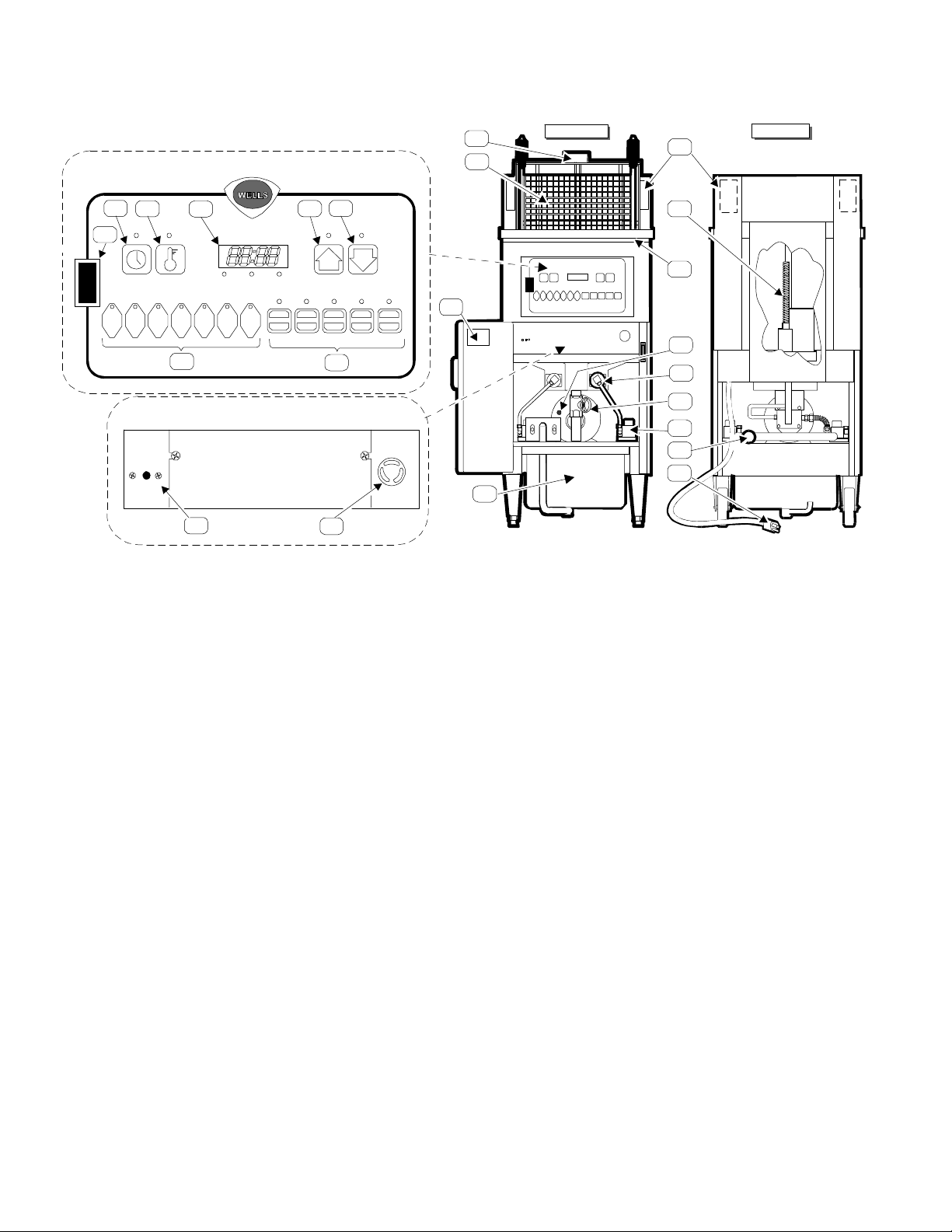
FEATURES and OPERATING CONTROLS
11
UPPER CONTROL PANEL
6
3
1
4
52
12
FRONT VIEW
14
15
FRYER
OFF
FILTER
1 2 3 4
TIME TEMP
HI-LIMIT
RESET
7
9
HEAT READY MANUAL
MANUAL
5 6
PAUSE CLEAN STANDBY BASKET FILTER
7
LOWER CONTROL PANEL
23
8
13
10
16
18
19
20
21
22
1. POWER SWITCH FRYER position turns ON the FRYER and energizes the UPPER
(FRYER-OFF-FILTER) CONTROL PANEL; and, turns OFF the FILTER PUMP.
Burner circuits are energized and regulate to the programmed
temperature.
OFF position turns OFF the FRYER .
FILTER position energizes the FILTER PUMP.
2. TIME KEY Used to check and set menu times.
3. TEMP KEY Used to check and set menu temperatures.
4. READOUT LED display of various data and functions.
5. UP ARROW KEY Used to raise FRY BASKET and raise program settings .
6. DOWN ARROW KEY Used to lower FRY BASKET and lower program settings .
7. MENU KEYS Used to begin a menu time/temp cycle.
Keys 1 thru 6 are programmable for time and temperature;
Key 7 is available for individually set time/temp cook cycles
8. FUNCTION KEYS Used to perform the functions of PAUSE, CLEAN, STANDBY,
BASKET (raise/lower) and FILTER (warning/acknowledge)
9. HI-LIMIT THERMOSTAT Provides over-temperature protection by de-energizing the
GAS VALVES if the oil temperature exceeds the factory-set
limit. RESET must be performed manually. Allow the oil to
cool below 350ºF (177ºC), then firmly press the red button on
the LOWER CONTROL PANEL until it “clicks”.
2
Page 5

CAUTION: FIRE HAZARD / HOT OIL
THE HI-LIMIT THERMOSTAT IS A FIRE PROTECTION DEVICE.
If tripping persists, contact your authorized Wells service agency for repairs.
DO NOT ATTEMPT TO BYPASS OR HOLD IN THE BUTTON OF THE
HI-LIMIT THERMOSTAT. A FIRE WILL RESULT.
10. SONALERT Audible alarm to signal end of a cook cycle and other programmed
functions.
11. LIFT CRADLE Raises and lowers FRY BASKET.
12. FRY BASKET Sits on the LIFT CRADLE and holds product to be cooked.
Raised and lowered by the LIFT CRADLE.
13. OIL FILTER RESERVOIR Holds the filter element. Holds oil during filtering cycle.
14. EXHAUST FLUE Twin flues. Hot flue gases exit here.
15. LIFT MOTOR Raises / lowers LIFT CRADLE. Accessible for lubrication thru
the access plate in back panel.
16. VENTILATION SLOT Provides air inlet for COOLING FAN inside CONTROL PANEL.
NEVER ALLOW WATER TO GET INTO THIS SLOT.
17. FILTER PUMP MOTOR The FILTER PUMP MOTOR is equipped with an over-
RESET BUTTON heating protection device.
RESET must be performed manually. Allow the motor to
cool for approx. 15 min., then firmly press the red button on
the back of the motor until it “clicks”.
18. BURNER ASSEMBLY Two assemblies; comprised of orifice, shutter, burner and ignitor.
19. DRAIN VALVE OVAL Opens and closes the DRAIN VALVE.
HANDLE To OPEN, turn the handle counterclockwise (to vertical).
To CLOSE, turn the handle clockwise (to horizontal).
20. GAS SHUT-OFF VALVES Two valves, one located behind each gas control valve. Allow
isolation of either burner circuit.
21. GAS CONNECTION Gas supply connects here.
22. POWER CORD 115V 15Amp, NEMA 5-15P
23. DATA PLATE Identifies the appliance manufacturer, model and serial number;
also gives electrical ratings, gas ratings.
3
Page 6
SAFETY PROCEDURES
Knowledge of proper procedures is essential to the safe operation of gas-fired cooking
equipment. In accordance with generally accepted product safety labeling guidelines for
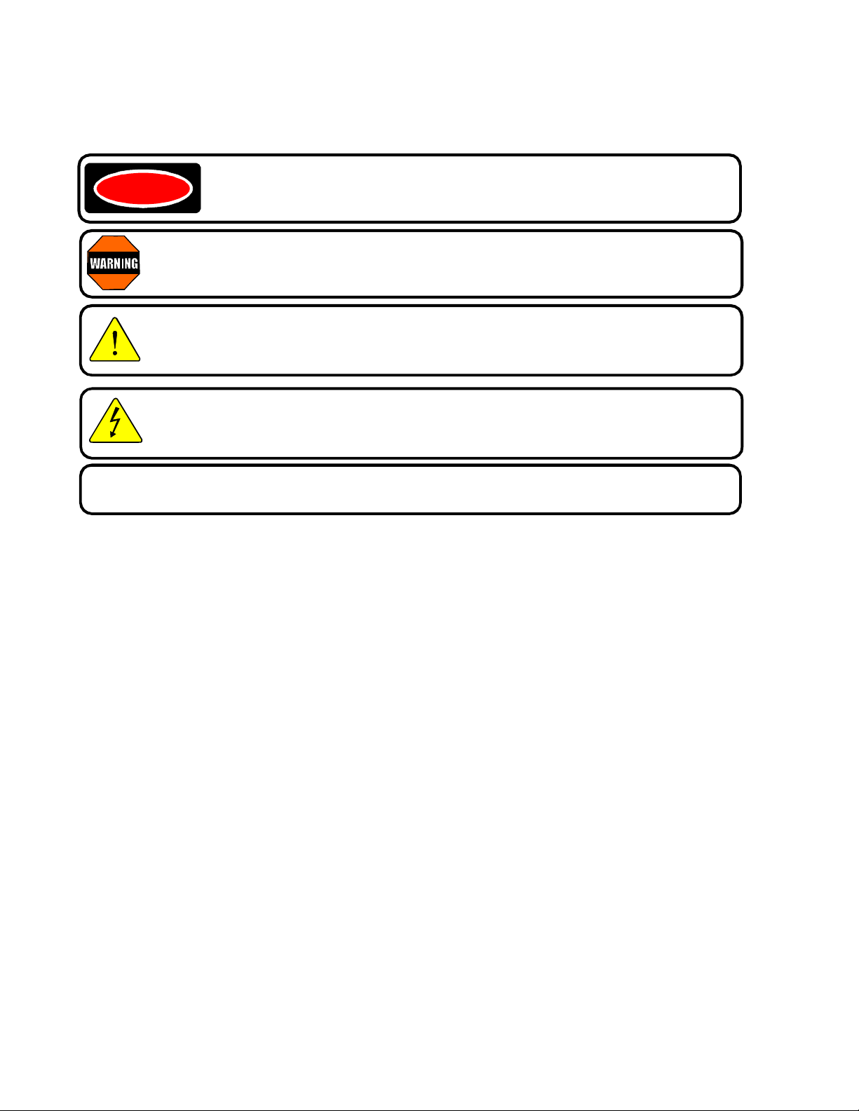
potential hazards, the following signal words and symbols are used throughout this manual.
DANGER - Danger is used to indicate the presence of a hazard which will
DANGER
WARNING - Warning is used to indicate the presence of a hazard which can cause
personal injury and possibly death, or major property damage, in the event the statement is ignored.
CAUTION - Caution is used to indicate the presence of a hazard which will or can
cause minor personal injury, or property damage in the event the statement is ignored.
CAUTION - Used to indicate the presence of an electrical hazard which will or can
cause personal injury, or property damage in the event the statement is ignored.
cause severe personal injury, death, or substantial property damage in the
event the statement is ignored.
NOTE - Note is used to notify personnel of installation, operation or maintenance information
which is important, but not hazard related.
FRYER PRECAUTIONS AND GENERAL INFORMATION
1. This fryer is intended for use to deep fry food products for human consumption. No other use
is recommended or authorized by the manufacturer or its agents.
2. This fryer is intended for use in commercial establishments, where all operators are familiar with
the appliance use, limitations and associated hazards. OPERATING INSTRUCTIONS AND
WARNINGS MUST BE READ AND UNDERSTOOD BY ALL OPERATORS AND USERS.
3. Your WELLS fryer is equipped with an oil filtration system, which is designed to filter hot liquid
shortening ONLY. Water, cleaning agents or other liquids will damage the FILTER PUMP.
4. This piece of equipment is made in the USA and has American sizes on hardware.
5. Any trouble shooting guides, component views or parts lists included in this manual are for general
reference only, and are intended for use by qualified technical personnel.
6. This manual should be considered a permanant part of this appliance. This manual and all
supplied instructions, diagrams, schematics, parts break downs, notices and labels must remain
with the appliance if it is sold or moved to another location.
4
Page 7

INSTALLATION INSTRUCTIONS
A. UNPACKING AND INSPECTION
1. Carefully remove the FRYER from the carton. Remove all blue protective plastic film,
packaging materials and accessories from the FRYER and the FILTER RESERVOIR before
connecting electrical power to the FRYER or otherwise performing any installation procedures.
NOTE: DO NOT discard the CARTON and other PACKAGING MATERIAL until you have
inspected the fryer for hidden damage and tested it for PROPER OPERATION.
Refer to SHIPPING DAMAGE CLAIM PROCEDURE on the inside front cover of this manual.
2. Read all instructions in this manual carefully before starting installation of this fryer. READ
AND UNDERST AND ALL LABELS AND DIAGRAMS ATTACHED TO THE FRYER.
3. Carefully account for all components and accessories before discarding packing materials.
Store the accessories in a convenient place for later use:
COMPONENTS
1 ea. FILTER RESERVOIR
1 ea. FILTER LEAF with O-RING
4 ea. FILTER RESERVOIR SUCTION TUBE O-RING (on FILTER
RESERVOIR SUCTION TUBE)
1 ea. FRY BASKET, FULL SIZE
1 ea. LIFT CRADLE
1 ea. FRYPOT LID
ACCESSORIES
1 ea. LITERATURE PACKAGE
1 bx. FILTER POWDER
2 ea. HIGH TEMPERATURE BRUSHES
1 ea. STAINLESS STEEL SHOVEL
1 ea. CLEANOUT DOWEL (WOOD ROD)
1 ea. “T”-SHAPED SCRAPER w/ INSTRUCTIONS
B. SERVICE TECHNICIAN INSTALLATION NOTES
1. Installation and start up should be performed by an authorized installation company.
Installer must record fryer installation particulars on the CUSTOMER SERVICE DATA form on
page 27 of this manual.
2. Verify that this FRYER installation is in compliance with the specifications listed in this manual
and with local code requirements. THIS IS THE RESPONSIBILITY OF THE INST ALLER.
3. Certain codes require fryers to be restrained with a CABLE or other RESTRAINT DEVICE.
It is the RESPONSIBILITY OF THE INSTALLER to check with the AUTHORITY HA VING
JURISDICTION, in order to ascertain the applicability of this requirement to THIS SPECIFIC
FRYER INST ALLATION.
5
Page 8
C. EQUIPMENT SET-UP
GAS VALVE
1. A single WFGA-60FS gas-fired fryer requires a minimum of 700 cubic feet per hour (12 CFM)
make-up air. The ventilation for the kitchen must have sufficient capacity to prevent a
negative-pressure condition. DO NOT obstruct or restrict ventilation and make-up air required
to support combustion.
2. Setup the FRYER only on a firm, level surface. Clearances from all combustible and noncombustible construction is 1” minimum. The area around the fryer must be kept clear of
combustibles.
3. LEVELING: Verify that the fryer sits firmly ON BOTH CASTERS AND ON BOTH LEGS.
With a spirit level, check that the fryer is level front-to-back and side-to-side. With the
adjustable legs, adjust as required to level the fryer.
4. DO NOT obstruct the flow of the two exhaust flues (item 14) at the top rear of the fryer. It is
especially critical that gas supply piping and electrical supply cord and/or receptacle be routed
away from the path of the hot combustion fumes.
5. This fryer must be installed and operated under a ventilation hood conforming to all applicable
local codes. Combustion fumes must be vented in accordance with local codes.
6. Cooking and cleaning functions require unobstructed access. The frypot, control panel and
front access panel must be maintained free from obstructions. The rear access panel must be
accessible for maintenance.
D. PLUMBING INSTALLATION
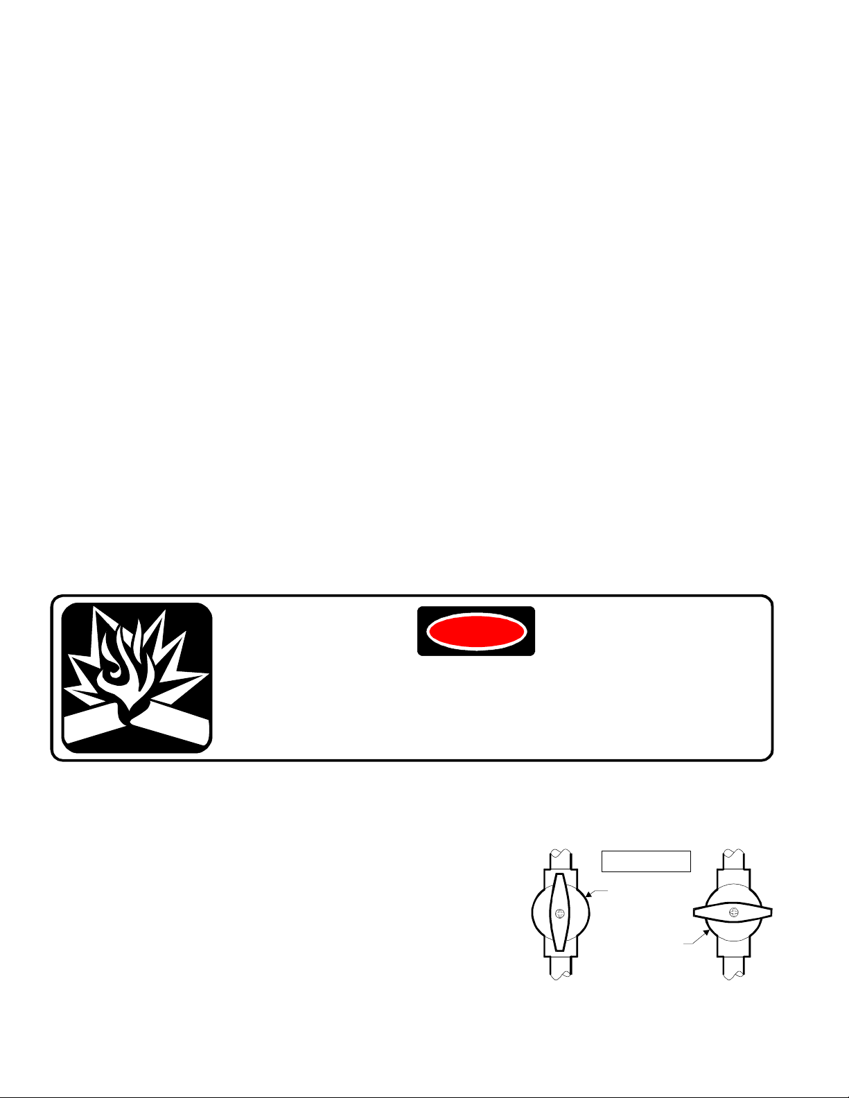
DANGER
FIRE AND EXPLOSION HAZARD
GAS CONNECTIONS AND GAS ADJUSTMENTS MUST BE MADE BY
A LICENSED PLUMBER, CERTIFIED IN GAS INSTALLATION
A gas explosion will cause death or serious injury.
1. The installation of this fryer must conform to local codes. In the absence of local codes, the
installation of this fryer must conform with the National Fuel Gas Code (ANSI Z223.1).
In Canada, the National Gas Installation Code (CAN/CGAB149.2) is applicable.
2. In any instance where gas supply pressure is in excess
of 15” water pressure (1/2 psi or 3.45kP), the fryer must
be isolated from the supply piping by closing its two
individual manual shut-off valves (item 20).
IMPORTANT: Failure to isolate the fryer from excessive
pressure will damage the gas valves and allow raw gas
to leak into the room.
OPEN
CLOSED
6
Page 9
3. This fryer is orificed at the factory for natural gas at a pressure of 3.5” of water column.
The installed orifice is suitable for use at -280 to 2999 feet (-85 to 914 meters) elevation.
It is the responsibility of the installer to install the factory recommended orifice and pressure
regulator kit suitable for the fuel type and elevation at the final installation site.
The red tag (p/n 301217) attached to the gas connection provides pressure settings and part
numbers for conversion kits applicable to various fuels and altitudes.
NOTE: Failure to install proper orifices can burn cooking oil and cause potential burner
and flue system failure.
Damaged caused by improper orifice installation is NOT covered by warranty.
E. ELECTRICAL INSTALLATION
1. Fryer electrical diagram and troubleshooting schematic (item 22) are located on the inside of
the fryer door.
2. The fryer is equipped with a three-prong grounding plug (NEMA 15-5P) for your protection
against shock hazard. The fryer must be plugged directly into a properly grounded three-prong
receptacle (NEMA 15-5R).
CAUTION - ELECTRICAL SHOCK HAZARD
DO NOT CUT OR REMOVE THE GROUNDING PRONG FROM THE PLUG.
Ungrounded electrical equipment cause personal injury
and property damage.
3. The installation of this fryer must conform to local codes. In the absence of local codes, the
installation of this fryer must conform with the National Electrical Code (ANSI Z223.1).
In Canada, CSA C22.2 is applicable.
4. Because the fryer draws less than 8 amps, two fryers may be plugged into the same 15 amp
circuit if required.
7
Page 10

E. EQUIPMENT PREPARATION PRIOR TO OPERATION
PIVOT
LIFT ROD
ASSEMBLED FILTER LEAF
(spout with O-RING inserts
RESERVOIR
RESERVOIR
FILTER RAIL “A”
Note: O-RING
RETAINING NUT
1. CLEANING: Prior to leaving the factory, the fryer is tested for proper operation with peanut oil.
After testing is complete, the oil is removed but oil residue remains. Therefore, it is necessary
to clean the frypot
2. Examine the CRADLE ROLLERS. Adjust or tighten as required. DO NOT operate the fryer
unless the CRADLE ROLLERS are in place and rotating freely. Serious damage to the frypot
will result if the rollers are not in position and operating properly.
3. Install the LIFT CRADLE onto the CRADLE PIVOT. Set the FRY BASKET on the LIFT
CRADLE.
before filling it with clean oil. See CLEANING THE FRYER, page 21.
ROLLER
LIFT CRADLE
4. Assemble the FILTER LEAF and install into the FILTER RESERVOIR. SUCTION TUBE
O-RINGS are shipped from the factory installed on the SUCTION TUBE; Examine to verify
one O-RING is in the groove closest to the end of the tube. Install the assembled FILTER
RESERVOIR into the fryer.
UPPER
FILTER SCREEN
SEPARATOR
LOWER
FILTER SCREEN
FILTER RAIL “B”
“O” RING
FILTER
ASSEMBLY
CROSS-SECTION VIEW
into drain opening)
O-RING for the filter reservoir
suction tube, and up to three spare
O-RINGS, are stored as shown:
STORAGE FOR 3
SPARE “O” RINGS
“O” RING IN
“O” RING GROOVE
8
Page 11

19
5. Close the OVAL DRAIN VALVE HANDLE (item 19)
COLD OIL LINE
by turning the handle to the CLOSED position.
NOTE: This fryer is designed for LIQUID SHORTENING ONLY. DO NOT USE SOLID
SHORTENING OR LARD. Solid shortening will solidify in the filter reservoir and filter
pump. This condition will render the filter system inoperable. Repairs caused by the use
of anything other than liquid shortening are not covered under warranty.
6. Fill the FRYPOT to the COLD OIL LINE
in the FRYPOT with cold commercial
FILL TO THIS LINE WITH COLD OIL
quality LIQUID SHORTENING.
This requires 60lbs. of oil.
IMPORTANT: Remember to fill the fryer to the COLD OIL LINE with fresh liquid shortening
prior to turning the POWER SWITCH to the FRYER position.
Energizing the fryer without oil can cause serious damage.
Damage due to operating the fryer without oil is NOT covered by warranty.
CLOSED
OPEN
.
7. Check operation of FRYER and all CONTROLS. See OPERATING INSTRUCTIONS, page10.
POTENTIAL FOR OIL OVERFLOW
The weight of product which can be safely cooked in this fryer will vary
with oil level, product moisture content, oil temperature, and other various
conditions. See Determine Maximum Load Weight below.
FAILURE TO OBSERVE THIS WARNING WILL RESULT IN HOT OIL
RELEASE FROM THE FRYER.
HOT OIL WILL CAUSE SEVERE BURNS ON CONTACT.
8. DETERMINE MAXIMUM LOAD WEIGHT: For operational safety, it is very important to
determine the maximum load weight for the specific operation. This can be accomplished by
starting out with small loads and gradually increasing to the largest load size which allows a
complete cook cycle without oil foaming out of the FRYPOT.
9
Page 12

OPERATING INSTRUCTIONS
BASKET
526
456
7
8a8b8c8d8e
HEAT READY MANUAL
PAUSE CLEAN STANDBY BASKET FILTER
WFGA-60FS with SOLID STATE CONTROLLER
NOTE: This fryer is equipped with two separate auto-ignition burner control systems.
On startup, each ignition system will try three times to prove its associated burner flame.
Failure to prove flame will result in shut-down of that burner circuit. Pressing the POWER
SWITCH to OFF, then back to FRYER will reset the fryer (and make three more tries).
The fryer may be operated safely (at reduced capacity) with only one burner operational.
A. PROGRAMMING THE KEY FUNCTIONS
3
1
TIME TEMP
1 2 3
4
MANUAL
7
As each control panel key is pressed, a “beep” will sound. The indicator light for each
key will light whenever the key is pressed, and while the function associated with that
key is active.
The FRYER - OFF - FILTER switch (item 1) allows the fryer to be placed in a normal cook
mode (FRYER), an oil-filtering mode (FILTER) or turned OFF.
TIME key (item 2) controls time functions.
TEMP key (item 3) controls temperature functions. Data can be read on the solid state
READOUT (item 4).
The HEAT indicator is lit whenever the burners are energized; the READY indicator is lit when
the oil is at the programmed temperature. The MANUAL indicator is lit whenever MENU key 7
is selected.
MENU keys (item 7) allow a choice of six (or seven) pre-programmed time / temp settings.
1
you to cook breasts and thighs longer than the wings and drumsticks by audibly beeping, and
displaying “DROP” on the readout (item 4). Your fryer installer can program this feature
into your controller upon request.
Arrow keys (item 5 & 6) control the basket lift (after pressing the
key,,
and are used to scroll through program settings.
Hint: MENU keys 1 and 2 incorporate a feature that will inform the operator when to
2
“drop” the wings and drumsticks during the cooking cycle. The “drop” feature will allow
10
Page 13

Hint: MENU key 7 is unprogrammed so that special or one-of-a-kind product may be
MANUAL
7
programmed any time. With the fryer ON, press and hold the TIME key and MENU 7
key at the same time. Press the UP or DOWN arrow key until the desired time is displayed. If
this MANUAL feature is not desired, MENU key 7 may be programmed in the identical fashion
to MENU keys 1 thru 6.
Note: The solid state controller is shipped from the factory with all seven MENU keys
(item 7) programmed for ZERO time and 325ºF (165ºC).
To program the controller for cooking your product you must first determine the cooking time
and temperature required to cook the product. Each MENU key may be programmed for a
different time and temperature, depending upon the requirements of each menu item.
It is the sole responsibility of the end user to determine the time and temperature
requirements of each menu item, and to program each MENU key to the determined
time and temperature in order to insure completely and safely cooked product:
TO PROGRAM MENU TIMES AND TEMPERATURES:
1. Make sure FRYPOT is filled with liquid cooking oil to the COLD OIL LEVEL line inscribed on
the inside of the FRYPOT. Do not over-fill or under-fill the fryer.
2. Set the POWER SWITCH (item 1) to FRYER. After 10 seconds, the readout will display
“ ”” “.
3. Enter the PROGRAMMING mode by pressing and holding + for three seconds, until
a beep sounds and “ ” is displayed on the readout (item 4).
Program MENU key 1 for the pre-determined cook time by pressing and holding + 1 at
the same time. Scroll to the desired time by pressing or until the desired time is
displayed on the readout.
Program MENU key 1 for the pre-determined cook temperature by pressing and holding
+ 1 at the same time. Scroll to the desired temp by pressing or until the
desired temperature is displayed on the readout. Range is 200ºF - 375ºF (93ºC - 191ºC).
MANUAL
4. Program MENU keys 2 thru 6 in the same manner.
MANUAL
MANUAL menu key. NOTE: Only
7
can be programmed while another MENU is cooking.
7
can be programmed, or left as a
5. Exit the PROGRAMMING MODE by pressing and holding + for one second.
The readout will display “ ” or “ ”” “.
6. Be sure to record which MENU key corresponds to which menu item or product to be cooked.
11
Page 14

B. USING THE FUNCTION KEYS (Item 8)
STANDBY
BASKET
FILTER
Halts the time countdown while any menu is running and time remaining is displayed
PAUSE
on the readout.
Purpose: Allows the user to raise the basket to inspect the product in the middle of a cook
cycle. Time remaining is frozen until the PAUSE key is pressed again.
To use: While a menu is running, press and hold the PAUSE key for five seconds, until a
beep sounds and the red indicator lights.
Raise the basket to inspect the product by pressing the BASKET key and UP arrow key.
Resume cooking the product by pressing the BASKET key and the DOWN arrow.
Resume the time countdown py pressing the PAUSE key.
To change the time remaining while in pause:
(a) This option uses the near-instant programming feature of the MENU 7 (MANUAL) key.
Press and hold the TIME key plus the MENU 7 key at the same time.
(b) Scroll in a new time remaining with the UP or DOWN arrow keys. Release all keys.
Press and hold the lit MENU key for three seconds. Display will read “00:00”.
Lower the basket by pressing the BASKET key followed by the DOWN arrow key.
Press the MANUAL (MENU 7) key. The basket will rise when the display reads “00:00”.
If the original menu time or temperature must be asjusted, see TO PROGRAM TIMES
AND TEMPERATURES, page 11.
Puts the fryer into the cleaning mode by setting the temperature to approximately
CLEAN
200ºF (94ºC) (i.e. just below the boiling point of water).
To Use: See CLEANING INSTRUCTIONS, page 21.
Puts the fryer into a “standby” mode for off-peak periods when the fryer is not needed,
but when it is not desirable to perform a complete oil cool down.
Purpose: This economy function allows the oil temperature to cool to 275ºF (135ºC) when the
fryer is not in use, but it is not desirable to turn the fryer off.
To use: While no menu is running and the display reads “00:00”, press and hold the
STANDBY key until a “beep” sounds and the red indicator lights.
To resume cooking after being in standby mode: Press and hold the STANDBY until a
“beep” sounds. The burners will be energized. Fryer is ready for use when the READY
light is lit.
Pressing this allows the UP and DOWN arrow keys to raise or lower the basket.
To Use: Press and release the BASKET key. The red indicator over the basket key will light.
Press and release either arrow key. The indicator for the selected arrow key will light. All
keys will be inactive for the ten seconds of the raise/lower cycle.
This key is only active in the pre-heat and pause modes, or when “00:00” is displayed.
Acknowledges a filter alarm. The filter alarm is programed to sound after a pre-set
number of cook cycles. This is factory pre-set to zero cycles. Your fryer installer
can alter the number of cycles upon request.
To Use: When the cycle count reaches the pre-set number, a “beep” will sound. Press and
release the FILTER key to cancel the alarm and reset the filter load counter to “zero”.
See FILTERING OIL, page 17.
12
Page 15

C. PRE-HEAT THE FRYER
BASKET
BASKET
Press a MENU key. If the oil temperature has not reached the programmed temperature, the
readout will display “ ”” “followed by the menu key #, and the HEAT indicator will
light. When the oil has reached the progammed temperature, the READY indicator will light, a
“beep” will sound five times and the readout will display “ ”.
The readout will normally display the time remaining. To display the oil temperature of the lit
menu item, press .
D. TO COOK PRODUCT
CAUTION:
BURN HAZARD / HOT OIL SPLATTER
HOT OIL CAN CAUSE SERIOUS BURNS ON CONTACT.
WEAR PROTECTIVE CLOTHING WHEN COOKING.
1. Press MENU key 1 thru 6 (item 7) for the desired menu item.
When the oil reaches the programmed temperature for that MENU key, the READY light
will go on, the HEAT light will go off and five “beeps” will sound.
2. FROZEN PRODUCT: Set the BASKET on the LIFT CRADLE in the raised position. Load
frozen product into the BASKET. Lower the BASKET by pressing
, then . When the
basket is fully down, start the timed cycle by pressing the appropriate MENU key. The basket
will raise automatically (and the 10 second buzzer will sound) at the end of the timed cycle.
3. FRESH PRODUCT: Set the BASKET on the LIFT CRADLE in the raised position. Lower the
BASKET by pressing
, then . Manually drop each piece of fresh product into the hot
oil just above the oil level to minimize splattering. ALWAYS USE PROTECTIVE EQUIPMENT,
SUCH AS INSULATED GLOVES, TO PROTECT AGAINST HOT OIL BURNS. For chicken,
drop thighs and breasts first, followed by drumsticks, then wings. Start a timed cycle by
pressing a MENU key.
Hint: MENU keys 1 and 2 incorporate a feature that will inform the operator when to “drop” the
wings and drumsticks during the cooking cycle. The “drop” feature will allow you to cook
breasts and thighs longer than the wings and drumsticks by audibly beeping, and displaying
“DROP” on the readout (item 4). Your fryer installer can program this feature into your
controller upon request.
4. Use the plastic-coated HANDLES of the basket to remove the basket of cooked product from
the LIFT CRADLE.
13
Page 16

MAINTENANCE INSTRUCTIONS
THREADS
CRADLE LIFT
BRASS
CRADLE
A. CRADLE LIFT ASSEMBLY LUBRICATION
PINCH HAZARD
DISCONNECT THE FR YER FROM ELECTRICAL POWER BEFORE
LUBRICATING THE CRADLE LIFT DRIVE SCREW.
Failure to disconnect power may allow the lift motor to
start unexpectedly, causing serious injury.
DRIVE
SCREW
GREASE
ACCESS
PANEL
NUT
LIFT
DRIVE
MOTOR
NOTE: Failure to keep the cradle lift screw properly lubricated will result in premature wear
of the brass lift nut Wear caused by lack of proper lubrication is NOT covered by warranty.
1. Disconnect the fryer from electrical power.
2. Open the rear access panel. Coat the exposed threads of the cradle lift screw with moly
(molybdenum disulfide) grease.
3. Close the access panel and restore electrical power.
4. Recommended frequency is “as required”, and, at a minimum, every six months.
Lubricate the cradle lift screw immediately if a grinding or rubbing noise is heard as the
basket is raising.
14
Page 17

B. CRADLE ROLLER ASSEMBLIES
TOP VIEW SIDE VIEW
SLIPPING & FALLING HAZARD / SPILLED OIL
DO NOT USE CRADLE IF THE ROLLERS DO NOT SPIN FREELY.
REPLACE ROLLERS IMMEDIA TELY IF THEY ARE FROZEN.
Oil spills may occur.
Death or serious injury may result from falls caused by slipping in oil
1. DAILY: Wash the cradle in the dishwasher or in the sink with
warm water and mild soap or detergent.
2. Thoroughly flush the bearings in the rollers with hot water
(under the faucet or with a spray nozzle).
Rinse the cradle thoroughly and dry.
3. Check the rollers to be sure they roll freely. Check bearing
nuts - keep them tight!
NOTE: Smooth operation of the rollers is essential to the
life of the fry kettle. If the rollers donot spin freely during
operation, they will soon wear grooves through the frypot wall.
IF ROLLERS ARE FROZEN OR OTHERWISE FOUND TO NOT SPIN FREELY AFTER
BEING THOROUGHLY CLEANED, REPLACE THEM IMMEDIATELY.
Wear to the FRYPOT caused by frozen rollers is NOT covered by waranty.
C. FILTER LEAF ASSEMBLY
STRAIGHT PIN
FILTER RAIL “A”
FILTER SCREEN
UPPER
SEPARATOR
FILTER SCREEN
FILTER RAIL “B”
LOWER
“L”-SHAPED PIN
15
Page 18

DANGER
BURN HAZARD / HOT OIL SPLATTER
DO NOT REMOVE FILTER RESERVOIR WHEN IT CONTAINS HOT OIL.
Contact with hot oil can cause death or serious injury.
PROTECTIVE CLOTHING AND GLOVES MUST BE WORN DURING
THE FILTERING PROCESS.
BURN HAZARD
DO NOT REMOVE EMPTY FILTER RESERVOIR IF IT IS HOT.
WEAR INSULA TED GLOVES, OR ALLOW IT TIME TO COOL.
The hot oil will quickly heat the reservoir. Serious burns could result from
touching the hot filter reservoir with bare hands.
Clean the FILTER LEAF after each day’s filtration, or as needed to return oil promptly to the kettle.
See diagram, page 15.
IMPORTANT: Make sure that all oil is returned to the FRYPOT before proceeding.
1. Open the FRYER DOOR and slide the FILTER RESERVOIR forward to remove it. Remove
the FILTER LEAF from the Reservoir.
2. Disassemble the FILTER LEAF by separating the two side rails at the joint with the straight pin.
Clean all components in a sink with warm water and mild detergent, or in a dishwasher.
3. Assemble the SCREEN with the SEPARATOR installed between the two screens. Verify that
the O-RING is in place on the suction tube on the BOTTOM SCREEN. See diagram, page 15.
4. Slide the screens into SIDE RAIL “B” (L-shaped pin). Note that the handle will point away
from the suction tube on the BOTTOM SCREEN. Hook SIDE RAIL “A” over the pin on
SIDERAIL “B” and work the screens into SIDERAIL “A” until the straight pin on SIDE RAIL “A”
is held by the “bump” on SIDERAIL “B”.
5. Install the FILTER LEAF in the FILTER RESERVOIR with the suction tube firmly into the filter
reservoir drain hole.
6. Inspect the “O” RING on the FILTER SUCTION TUBE for damage. Replace the “O” ring if it
is cut, cracked or scuffed.
7. Install the filter reservoir into the fryer. Make sure the “O” ring closest to the end of the
SUCTION TUBE is firmly seated in the SUCTION LINE RECEPT ACLE.
16
Page 19

D. FILTERING OIL
IMPORTANT: Filtering the cooking oil helps to ensure the quality of the food product.
Careful observation of the finished food product will help you determine your optimal filtering
frequency. (Example: filter the oil after each six loads of fresh breaded product.)
NOTE: Your Wells fryer filtration system is designed to filter hot liquid shortening ONLY.
Water, cleaning agents or other liquids will damage the FILTER PUMP.
DO NOT attempt to filter cold oil(less than 300ºF/149ºC).
DO NOT store oil in the FILTER RESERVOIR overnight, or other extended period.
DO NOT attempt to pump cold oil. The filter pump will not pump cold oil through the FILTER
LEAF. Pumping cold oil will result in premature failure of the FIL TER PUMP.
CAUTION:
BURN HAZARD / HOT OIL SPLATTER
PROTECTIVE CLOTHING AND GLOVES MUST BE WORN DURING
THE FILTERING PROCESS.
Hot oil may splatter, which could result in serious injury.
1. Press the POWER SWITCH (item 1) to the OFF position.
CAUTION: BURN HAZARD
THE FIL TER RESER VOIR MAY BE HOT.
WEAR INSULA TED GLOVES OR ALLOW THE FILTER
RESERVOIR TO COOL BEFORE TOUCHING IT.
IMPORTANT: Do not leave the FRYER unattended during the filtering process.
Continuously monitor the oil level in the reservoir to avoid overflowing the reservoir
and spilling oil on the floor.
2. Remove and examine the FILTER RESERVOIR. MAKE ABSOLUTELY CERTAIN THAT NO
WATER EXISTS IN THE BOTTOM OF THE PAN. Verify that the FILTER LEAF is properly
installed, and that the SUCTION TUBE O-RING is in place and in good condition. Install
the FILTER RESERVOIR ASSEMBLY into the FRYER, making sure the SUCTION TUBE is
properly seated in the SUCTION RECEPTACLE.
3. FILTER POWDER absorbs acids and other contaminants in the cooking oil, allowing the
cooking oil to be used for a longer period of time before it must be replaced. Carefully and
slowly add the contents of one package of FILTER POWDER to the oil in the FRYPOT.
17
Page 20

BURN HAZARD
PROTECTIVE CLOTHING AND INSULATED GLOVES MUST BE WORN
WHEN CLEANING THE KETTLE WITH THE HI-TEMP BRUSH AND
WHEN UNCLOGGING THE DRAIN WITH THE WOOD CLEANOUT DOWEL.
The kettle will be hot and hot oil may splatter. Serious injury may result.
4. Slowly rotate the OVAL DRAIN VALVE HANDLE (item 19) to the OPEN position.
The oil will drain from the kettle. If the kettle does not drain, unplug the drain by using the
WOOD CLEANOUT DOWEL provided with the fryer. Unplug the drain by pushing the dowel
down through the drain hole in the bottom front center of the kettle.
5. Press the POWER SWITCH to the FILTER position. The filter pump will circulate the oil
through the filter leaf, returning it to the kettle.
6. Using the HIGH TEMPERATURE BRUSH and “T”-SHAPED SCRAPER that were supplied
with the fryer, brush/scrape down the frypot sides and bottom to loosen crumbs and flush them
from the fryer.
BURN HAZARD - FILTER RESERVOIR
NEVER ATTEMPT TO REMOVE THE FILTER RESERVOIR WHEN IT IS
FULL OF HOT OIL.
Serious burns could result from any spillage of hot oil from the reservoir.
7. Be aware that filter powder and crumbs wil accumulate on the FILTER LEAF. If the oil is slow
to return to the frypot because of a plugged filter leaf, use the STAINLESS STEEL SHOVEL
supplied with the fryer to scoop the debris from the filter leaf top surface (see page 25).
8. When filtering is complete (5 -7 minutes of pump running with the drain valve open), rotate the
OVAL DRAIN VALVE HANDLE to the CLOSED position.
9. When bubbles begin to appear in the oil being pumped into the frypot, wait approximately
fifteen (15) seconds. Then, press the POWER SWITCH to the OFF position.
IMPORTANT: VERIFY THAT ALL OIL HAS BEEN RETURNED TO THE KETTLE AT
THE END OF THE FILTERING CYCLE.
10. Service the FILTER LEAF after each day’s filtration, or as needed to return oil promptly to the
kettle.
18
Page 21

E. DISCARDING USED OIL
IMPORTANT NOTE: The following instructions for discarding used oil from the fryer
may be disregarded if you use a WELLS MOBILE CADDY WAOC-1 (part no. 22470).
The WAOC-1 is a manual oil pump/removal system which allows you to hand pump the used
oil directly into the caddy, and to then hand pump the used oil into your oil disposal container
by simply reversing the pump rotation.
REMEMBER: Always, and without fail, allow the oil to cool prior to pumping the oil into
the OIL CADDY. HOT OIL WILL BURN YOU!
DANGER
OIL MUST COOL TO 120°F (49°C) OR COOLER
BEFORE DRAINING OIL FROM THE FRYER FOR DISPOSAL.
Normal operating temperature of the fryer is 375°F (191°C).
Death or serious injury will result from contact with hot oil.
BURN HAZARD / HOT OIL
SLIPPING & FALLING HAZARD / SPILLED OIL
DO NOT USE THE FILTER RESERVOIR TO DISCARD OIL.
DO NOT FILL DISPOSAL CONTAINER MORE THAN 1/4 FULL.
DO NOT LEAVE FRYER UNATTENDED WHEN DRAINING OIL.
Oil spills may occur.
Death or serious injury may result from falls caused by slipping in oil
BURN HAZARD - FILTER RESERVOIR
WHEN REMOVING THE FILTER RESERVOIR AFTER FIL TERING OIL,
WEAR INSULA TED GLOVES, OR ALLOW IT TIME TO COOL.
The hot oil will quickly heat the reservoir. Serious burns could result from
touching the hot filter reservoir with bare hands
19
Page 22

DISCARDING USED OIL WITHOUT USING THE WELLS MOBILE OIL CADDY
VALVE
HANDLE
1. Press the POWER SWITCH to the OFF position and allow the oil to cool to 120ºF (49ºC), or
less, before attempting to drain the oil from the fryer. All oil should be in the kettle Make sure
all oil has been returned to kettle, and there is no oil remaining in the filter reservoir.
2. Using suitable gloves, remove the FILTER
RESERVOIR.
Hint: This is an ideal time to run the FILTER
RESERVOIR and the disassembled FILTER
LEAF (see page 15) through the dishwasher.
3. Place a suitable METAL OIL DISPOSAL
CONTAINER under the DRAIN VALVE.
4. Slowly turn the OVAL DRAIN VALVE HANDLE
to the OPEN position. Fill the container no
more than 1/2 full.
Close the DRAIN VALVE and allow the oil
OIL
DISPOSAL
CONTAINER
to finish draining from the DRAIN PIPE before
removing the container. Dump the used oil into
your WASTE OIL CONTAINER. Continue
this process until the kettle is empty.
5. Close the OVAL DRAIN VALVE HANDLE.
6. Check the FILTER RESERVOIR to make sure the FILTER LEAF is properly installed.
MAKE ABSOLUTELY CERTAIN NO WATER EXISTS IN THE BOTTOM OF THE PAN.
Reinstall the FILTER RESERVOIR into the FRYER.
10. Clean up any spilled oil.
IMPORTANT: Remember to fill the fryer to the COLD OIL LINE with fresh liquid shortening
prior to turning the POWER SWITCH to the FRYER position. Energizing the fryer without
sufficient oil in the frypot will cause serious damage. Damage due to operating the fryer
without sufficient oil in the frypot is NOT covered by warranty.
20
Page 23

F. CLEANING THE FRYER
CLEANING THE KETTLE: HOT BOIL-OUT METHOD
SLIPPING & FALLING HAZARD / SPILLED OIL
DO NOT STORE OIL IN THE FIL TER RESER VOIR WHILE
CLEANING THE KETTLE. IF CLEANING FLUID IS ACCIDENTALLY
DRAINED INTO THE FILTER RESERVOIR, OIL WILL SPILL ON THE
FLOOR.
Death or serious injury may result from falls caused by slipping in oil
NOTE: Use a LOW-FOAMING COMMERCIAL FRYER CLEANSER ONLY.
1. Press the POWER SWITCH to the OFF position.
2. Discard old oil as detailed in DISCARDING USED OIL, page 19 and 20.
3. Fill the FRYPOT to the COLD OIL LINE with warm water.
CAUTION:
BURN HAZARD / HOT WATER SPLATTER
USE ONLY LOW-FOAMING COMMERCIAL FRYER CLEANER.
CAREFULLY FOLLOW CLEANSER INSTRUCTIONS AND WARNINGS.
DO NOT LEAVE FRYER UNATTENDED WHILE BOILING OUT THE
KETTLE. IF WATER FOAMING OCCURS, BE PREPARED TO TURN
THE POWER SWITCH “OFF”.
Boiling water could splatter and cause serious injury.
4. Press the POWER SWITCH to the FRYER position. Wait 10 seconds, then press and hold
CLEAN
for six seconds until a “beep” sounds and “BOIL” is displayed. Slowly add, and stir-in, the
LOW FOAMING COMMERCIAL FRYER CLEANSER. Stir until the cleanser is completely
mixed with the water using the HIGH TEMPERATURE BRUSH supplied with the fryer.
5. Time displayed is elapsed time. When the display reads “1:30”, press the POWER SWITCH
to the OFF position.
6. To exit CLEAN mode, press the POWER SWITCH OFF.
7. To avoid burns, allow the cleaning solution to cool to a safe handling temperature or dilute it
with cool water until a safe handling temperature is reached. With the POWER SWITCH in
the OFF position, drain the cleaning solution.
21
Page 24

NOTE: When using a metal container, allow the solution to cool to below 120ºF for safe
handling. Always safely dispose of used cleaning solution as required by local ordinances.
7. Rinse the kettle thoroughly with warm, clean water. Drain into the same container as used to
dispose of the cleaning solution.
IMPORTANT: NEVER turn the FILTER PUMP ON with anything other than commercial-
quality liquid shortening in the filter reservoir. Water will cause severe oil splattering, can
damage the pump and will contaminate the cooking oil.
CLEANING THE RESERVOIR
CLEAN THE RESER VOIR ONLY WHEN EMPTY. The FILTER RESERVOIR and FILTERLEAF
should be cleaned after each day’s filtration, or as needed to return oil promptly to the kettle.
BURN HAZARD - FILTER RESERVOIR
WHEN REMOVING THE FILTER RESERVOIR AFTER FIL TERING OIL,
WEAR INSULA TED GLOVES, OR ALLOW IT TIME TO COOL.
The hot oil will quickly heat the reservoir. Serious burns could result from
touching the hot filter reservoir with bare hands.
1. Remove the empty FILTER RESERVOIR from the fryer. Wash the FILTER RESERVOIR and
the FILTERLEAF components in the dishwasher, or in the sink, using mild soap or detergent.
2. Rinse thoroughly with clean warm water to remove all residue. Be sure to flush out the FILTER
RESERVOIR SUCTION TUBE. Tip the FILTER RESERVOIR upside down and allow all water
to drain from the reservoir and suction tube.
3. Dry all parts thoroughly with a non-abrasive cloth.
4. Assemble and reinstall the FILTER LEAF and FILTER RESERVOIR. Refer to page 8.
DAILY CLEANING OF FRYER
1. FRYER EXTERIOR: As required, wash the exterior of the fryer with warm water, mild soap or
detergent, and a clean, non-abrasive cloth. Dry with a clean, non-abrasive cloth.
22
Page 25

TROUBLESHOOTING
STANDBY
WFGE-60FS
NOTE: Any servicing or adjustment which requires the removal of any cover or other
protective panel, and all programming not accessible from the user menu, must be
performed by a Wells Mfg. Authorized Service Agency.
A. PROBLEM: FRYER WILL NOT HEAT WHEN POWER SWITCH IS IN FRYER POSITION
1. If: DISPLAY (item 4) NOT lit: Check the SERVICE POWER BREAKER. Reset if TRIPPED.
If breaker continues to trip, contact a licensed electrician to repair field wiring (if that is the
cause), or contact a Wells Mfg. Authorized Service Agency for repairs.
2. If: DISPLAY (item 4) LIT, READY indicator lit & HEAT indicator not lit:
a. Fryer is at programmed temperature. Display reads “00:00”.
Check programmed temperature by pressing .
If programmed temperature is too low, adjust temperature (see page 11) or select
another menu key.
b. Fryer is in CLEAN mode. If CLEAN indicator is lit and display reads “BOIL”, press
POWER SWITCH to the OFF position, wait ten seconds, then press POWER
SWITCH back to the FRYER position.
c. Fryer is in STANDBY mode. If the STANDBY indicator is lit, press
seconds until a beep sounds. Press and release a menu key to resume cooking.
d. Otherwise, contact a Wells Mfg. Authorized Service Agency for repairs.
3. If: DISPLAY (item 4) lit & HEAT indicator lit: Check the HI-LIMIT THERMOSTAT (item 9).
Reset by firmly pressing the HI LIMIT RESET button on the LOWER CONTROL PANEL until
it “clicks” .
for three
CAUTION: FIRE HAZARD / HOT OIL
THE HI-LIMIT THERMOSTAT IS A FIRE PROTECTION DEVICE.
If tripping persists, contact your authorized Wells service agency for repairs.
DO NOT ATTEMPT TO BYPASS OR HOLD IN THE BUTTON OF THE
HI-LIMIT THERMOSTAT. A FIRE MAY RESULT.
4. If: DISPLAY (item 4) LIT, HEAT indicator (item 3) lit & HI-LIMIT THERMOSTAT not tripped:
Probable cause is misadjustment or a damaged internal component. Contact a Wells Mfg.
Authorized Service Agency for repairs.
23
Page 26

B. PROBLEM: BURNERS WON’T LIGHT or “POP” WHEN IGNITING
BASKET
BASKET
1. Verify that GAS SHUTOFF VALVES (item 20) are in the fully OPEN position.
2. Verify that gas pressure regulators are adjusted to recommended pressure (must be performed
by a qualified technician).
3. Damaged or mis-adjusted internal component(s). Contact a Wells Mfg. Authorized Service
Agency for repairs.
C. PROBLEM: CRADLE LIFT WILL NOT LOWER or
CRADLE LIFT WILL NOT RAISE
1. The CRADLE LIFTmust be lowered manually, but will raise automatically at the end of a cook
cycle. During the period between cook cycles, in the PAUSE mode, or during PRE-HEAT, the
CRADLE LIFT is lowered by pressing
, then , and raised by pressing
then .
2. The lift motor has a ten second delay (after an up or down command is entered) until it will
acceptanother command. The lift motor is de-energized during a cook cycle, except when the
PAUSE
key is pressed (see page 12).
3. At the end of a cook cycle, when the time remaining on the READOUT reaches 00:00, the
CRADLE LIFT should raise.
4. If the CRADLE LIFT does not behave as described above, probable cause is a damaged
controller or relay, an internal adjustment, or one or more damaged internal components.
Contact a Wells Mfg. Authorized Service Agency for repairs.
D. PROBLEM: FILTER PUMP WILL NOT RUN
1. Verify that the POWER SWITCH is in the FILTER position.
2. Press the red RESET button (item 17) on the FILTER
PUMP MOTOR, accessible through the front door.
If the pump motor continues to trip out, or if no other
PUMP MOTOR
OVERLOAD
RESET
cause is apparent for the pump’s failure to run, contact
a Wells Mfg. Authorized Service Agency for repairs.
24
Page 27

E. PROBLEM: OIL NOT RETURNING TO FRYPOT DURING FILTER CYCLE
CAUTION:
BURN HAZARD / HOT OIL SPLASH / SPLATTER
PROTECTIVE CLOTHING AND GLOVES MUST BE WORN
WHENEVER SERVICING THE FILTER DURING THE FILTERING
CYCLE
Hot oil may splatter, which could result in serious injury.
The surface of the FILTER LEAF may become clogged with crumbs or other debris. If this
happens:
a. Turn OFF the OVAL DRAIN VALVE HANDLE (item 19) and press the POWER
SWITCH to OFF.
b. Using appropriate gloves, carefully and very slowly slide the FILTER RESERVOIR out
approximately 6”. Gently run the STAINLESS STEEL SHOVEL across the surface of
the FILTER LEAF and scrape the crumbs toward the rear. Carefully and very slowly
slide the FILTER RESERVOIR back into place, making sure the SUCTION TUBE is
properly seated in the RECEPTACLE.
F. PROBLEM: FILTER PUMP WON’T PUMP, or PUMPS AIR DURING FILTERING
BUBBLES in the oil while filtering, and/or a failure of the pump to achieve or maintain prime
indicate that air is entering the suction side of the pump.
1. Examine the SUCTION TUBE O-RING. A damaged
or improperly seated O-RING can cause the FILTER
PUMP to lose suction. This will result in a failure to
filter the oil, and in a failure of the oil to be returned to
the FRYPOT.
Replace SUCTION TUBE O-RING if it is missing,
cracked, distorted or scuffed.
2. Verify that he SUCTION TUBE is fully seated in the
SUCTION LINE RECEPTACLE.
25
Page 28

SERVICE PARTS LIST
IMPORTANT: Use only factory authorized service parts and replacement filters.
For factory authorized service, or to order factory authorized replacement parts, contact your
WELLS AUTHORIZED SERVICE AGENCY, or call:
Wells Manufacturing Company, Service Parts Department
2 Erik Circle, P. O. Box 280
Verdi, NV 89439
phone: (775) 345-0444 Ext.504 fax: (888) 492-2783
Service Parts Department can supply you with the name / telephone number of the WELLS
AUTHORIZED SERVICE AGENCY nearest you.
FRYER ACCESSORIES PART#
BASKET, FULL SIZE 22441
BASKET, 1/2 SIZE 22448
LIFT CRADLE 69961
FLAVOR SA VER OIL FIL TER POWDER (45 pk) 22410
WAOC-1 MOBILE OIL DISPOSAL CADDY 22470
PADDLE, STIRRING CHICKEN 22515
BRUSH, FRYPOT CLEANING 22516
FILTER LEAF ASSEMBLY 501904
STAINLESS STEEL SHOVEL 501901
KETTLE COVER 502039
NORMAL MAINTENANCE ITEMS PART #
LUBE, MOL YDISULFIDE (LOCAL PURCHASE)
“O” RING, SUCTION TUBE (pk 5) 66474
DOWEL, DRAIN CLEANOUT 69752
OVAL DRAIN VALVE HANDLE 501163
“O” RING, FILTER LEAF 501900
ORIFICE KIT, NATURAL GAS BELOW 3000 FT 502140
ORIFICE KIT, NATURAL GAS 3000 - 5999 FT 502141
ORIFICE KIT, NATURAL GAS 6000 - 8999 FT 502142
ORIFICE KIT, NATURAL GAS ABOVE 9000 FT 502143
ORIFICE KIT, PROPANE BELOW 2000 FT 502144
ORIFICE KIT, PROPANE 2000 - 6999 FT 502145
ORIFICE KIT, PROPANE ABOVE 7000 FT 502146
26
Page 29

NOTES
CUSTOMER SERVICE DATA
please have this information available if calling for service
RESTAURANT _____________________________ LOCA TION _______________
INSTALLATION DA TE ________________________ TECHNICIAN _____________
SERVICE COMP ANY __________________________________________________
ADDRESS ___________________________ ST ATE ______ ZIP__________
TELEPHONE NUMBER (_____)_____-_________
EQUIPMENT MODEL NO. ______________________________________________
EQUIPMENT SERIAL NO. ______________________________________________
VOLTAGE: (check one) 120V 208V 240V
27
Page 30

WELLS MANUFACTURING COMPANY
2 ERIK CIRCLE, P. O. Box 280
Verdi, NV 89439
Customer Service (775) 345-0444 Ext. 502
fax: (775) 345-0569
www.wellsbloomfield.com
 Loading...