

Page 1
WFE-40 ELECTRIC FLOOR FRYER
INSTRUCTIONS
Installation
Operation
Maintenance
WELLS MANUFACTURING COMPANY
P.O. BOX 280 VERDI, NEVADA 89439 (702) 345-0444
FAX 702-345-0569
Item No. 46634
10/92
Page 2

TABLE OF CONTENTS
DESCRIPTION PAGE
Warranty 3
Shipping Claim Procedure 4
Specification Information 4
Warnings! 5-6
Controls and Functions 7-8
Installation Instructions 9-10
Operating Instructions 10-11
Filtering Instructions 11-14
Cleaning Instructions 14-15
Warranty Exclusions 16
2
Page 3

WARRANTY STATEMENT
All commercial cooking equipment manufactured by WELLS has a warranty against defects in materials and
workmanship for one year from the date of original installation, or eighteen months from the date of shipment from our
factory, whichever comes first. This is for the benefit of the original purchaser only. A. The stainless steel fry pots in
gas fryers, model number WFG-40-2, warranty insures fry pots to be free from defects that could cause shortening
leaks for five years from date of purchase. The exception is that after one year the replacement of the fry pot under
warranty will cover at 75% of list price of kettle assembly. Fry kettle includes new shrouds, insulation, flue vent,
burners, thermostats and attaching hardware; travel and labor not included. Fry pots, which fail due to abuse, will not
cover in standard or five year warranty - items include but not limited to firing of burners without shortening or other
cleaning solution in the fry kettle at proper level.
B. with respect to Lite Line Products, warranty is one year parts and labor
on carry-in portable models.
THIS WARRANTY IS THE COMPLETE AND ONLY WARRANTY, EXPRESSED OR IMPLIED IN LAW OR
FACT, INCLUDING BUT NOT LIMITED TO, WARRANTIES OF MERCHANTABILITY OR FITNESS FOR
ANY PARTICULAR PURPOSE, AND FOR DIRECT, INDIRECT OR CONSEQUENTIAL DAMAGES
CONCERNING WELLS' PRODUCTS. This warranty is void if it is determined that upon inspection by an authorized
service agency that the equipment has been modified, misused, misapplied, improperly installed, or damaged in transit
or by fire, flood or act of God. Also, warranty does not apply if the serial nameplate has been removed or service is
performed by unauthorized personnel. The prices charged by Wells for its products are based upon the limitations in
this warranty. Seller's obligation under this warranty limits to the repair of defects without charge by a WELLS' factory
authorized service agency or one of its sub-service agencies and limits to a sixty mile radius to the nearest authorized
service agency or one of its sub-service agencies. This service will be provided on customer's premises for nonportable models. Portable models (a device with a cord and plug) must be taken or shipped to the closest authorized
service agency, transportation charges prepaid for service. Besides restrictions contained in this warranty, specific
limitations show in the Service Policy and Procedure Guide. WELLS' authorized service agencies location are in
principal cities. This warranty is valid in the United States and Canada and void elsewhere. Please consult your
classified telephone directory, your foodservice equipment dealer or write the Factory Service Department, Wells
Manufacturing Company, P.O. Box 280, Verdi, Nevada 89439, phone (702) 345-0444, for information and other
details concerning warranty.
3
Page 4

SHIPPING CLAIM PROCEDURE:
For your protection, please note that equipment in this shipment was carefully inspected and packed by skilled personnel
before leaving the factory. The transportation company assumes full responsibility for safe delivery upon acceptance of this
shipment.
IF SHIPMENT ARRIVES DAMAGED:
1. VISIBLE LOSS OR DAMAGE— Be certain this is noted on freight bill or express receipt and signed by person
delivering.
2. FILE CLAIM FOR DAMAGES IMMEDIATELY— Regardless of extent of damage.
3. CONCEALED LOSS OR DAMAGE— If damage is unnoticed until merchandise is unpacked, notify transportation
company or carrier immediately, and file "concealed damage" claim with them. This should be done within (15) days
of date of delivery is made to you. Be sure to retain container for inspection.
We cannot assume responsibility for damage or loss incurred in transit. We will, however, be glad to furnish you with the
necessary documents to support your claim.
SPECIFICATION INFORMATION:
Dimensions: 15 5/8 " x 32" x 41"
Shortening Capacity: 30 to 40 Ibs.
Electrical Rating: See Chart
Number of Phase: 3F only
Frequency: 50/60 Hz
KW 208V 240V 480V
LI L2 L3 L1 L2 L3 L1 L2 L3
14
17 47.2 47.2 47.2 40.9 40.9 40.9 20.5 20.5 20.5
38.9 38.9 38.9 33.7 33.7 33.7 16.9 16.9 16.9
NOMINAL CURRENT DRAW
4
Page 5
WARNINGS!
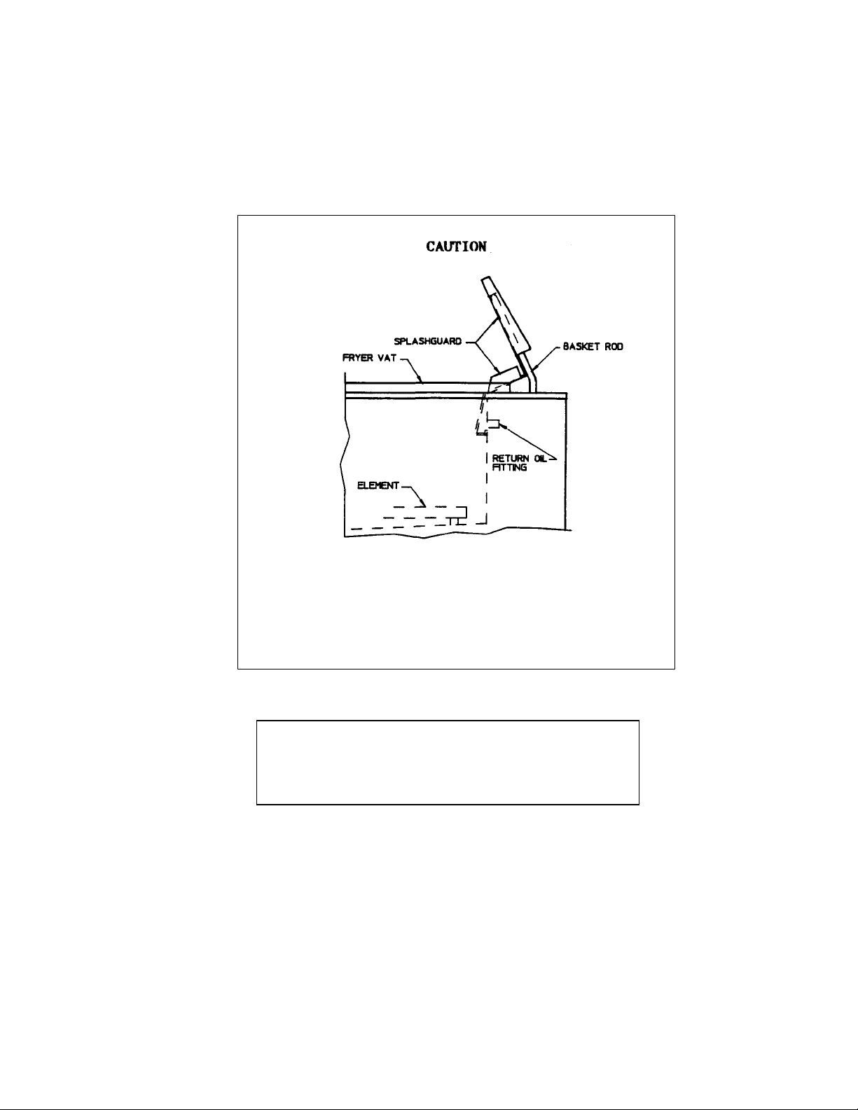
The hinged oil splashguard may be raised for cleaning ONLY.
To avoid serious injury the splashguard must be in the down
(shown above) position before operating the fryer or the filter.
Splashing of HOT OIL may occur if the oil splashguard is not in
the down position.
WARNING!
To avoid injury protective clothing and insulated
gloves must be worn during filtering, cleaning the
fry vat and discarding used oil.
5
Page 6

WARNINGS!
WARNING!
DO NOT ATTEMPT OR RELOCATE THE FRYER WITHOUT THE
ASSISTANCE OF AN AUTHORIZED SERVICE AGENCY. DO NOT
MOVE THE FRYER WITH HOT OIL IN THE VAT. COOL DOWN
OIL TEMPERATURE TO BELOW 135°F. HOT OIL SPILLAGE
WILL CAUSE SEVERE BURNS!
CAUTION
DO NOT LEAVE OIL IN THE FILTER RESERVOIR FOR EXTENDED
PERIODS OR OVERNIGHT. Wells built-in filter system
is designed to handle hot oil only. The filter pump
will not pump cold oil or solid shortening.
The built-in filter system is designed for OIL ONLY.
Water, cleaning agents or other liquids will damage
the filter pump.
6
Page 7
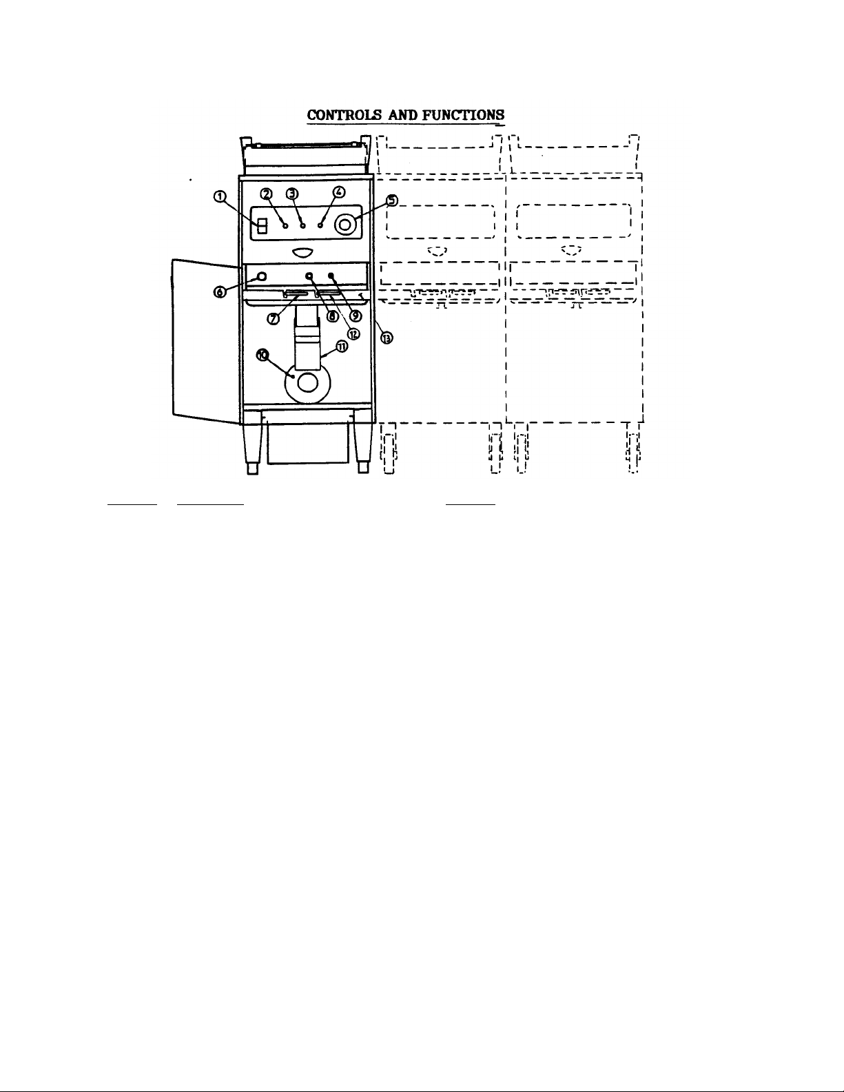
Item No. Description Function
1. Three Position Rocker Switch "FRYER" position turns ON the
FRYER-OFF-FILTER fryer and the WHITE power light.
"OFF" position turns OFF the fryer
"FILTER" position turns ON the filter
motor for single fryers, while fryer
"FILTER" position for the banked
fryers makes power available to the
are OFF in this position.
2. Power Light...White When ON indicates power is available
3. Hi-Limit Light—Red When ON this indicates that the
system has allowed the oil to over
have shut off. Wait approximately
five (5) minutes, open the door and
complete information).
and the filter system.
elements are OFF in this position.
filter motor, while fryer elements
either to the Fryer or Filter Motor.
heat, and the fryer heating elements
press reset button (see item 9 for
7
Page 8

4. Heat on Light... Amber When ON it indicates that the Fryer
5. Solid State Temperature This controls the oil temperature
CAUTION: Power switch MUST be used for positive OFF. DO NOT SHUT OFF the
6. Fuse Provides electrical over current
7. Drain Valve Handle Open and closes drain valve.
* 8. Filter Light...Green When ON it indicates that the filter
9. Hi-Limit Thermostat The function of this thermostat is to
* 10. Motor Reset Button The motor is equipped with an
11. Drain Spout Adjustable gutter to lead discharged
**12. Oil Return Valve Handle Open or close oil return valve. If
**13. Interlock Channel Slide side to side when all valves are
Controller from 0° to 375°F.
unit with the solid state temperature controller.
(at back side of motor) overheating protection device. Wait
heating elements are ON. Cycles OFF
when oil reaches preheat
temperature.
protection for the fryer. Use a 10
AMP SC type replacement only.
motor is ON.
shut down the fryer heating elements
in the event of over heated oil.
for the motor to cool down
(approximately 15 minutes). Press the
reset button to restart the motor.
oil to the filter reservoir or
discarding bucket.
main power switch is at the FILTER
position, turning the valve open will
automatically turn filter motor ON,
while turning the valve close will
automatically shut the motor OFF.
closed or rotate clockwise to the up
position and select fryer section to
drain and/or filter, minimizes
overflow to filter reservoir and
fryer vat.
* Available for Fryers with a Filter.
** Available for two or more Banked Fryers with Filters.
8
Page 9

INSTALLATION INSTRUCTIONS:
1. Start Up
2.
A. When moving the fryer with filter and/or casters, remove filter
B. An authorized service agent should install the fryer and perform the
C. The power supply must be rated the same as the unit being installed.
reservoir to allow free swiveling caster action.
initial start up procedures.
Leveling
A. Check that the unit sits firmly on all four legs and is level.
B. For fryers with casters, lock all front casters by pressing the brake
lever ON treadle (see figure below.)
3. Cleaning
A. Prior to leaving the factory the fryer is tested for proper
operation. Oil is placed in the fryer vat and the thermostat is calibrated. After testing is complete the
oil is removed, but residue remains. Therefore, it is necessary to clean the fryer vat before filling with
fresh oil. Refer to cleaning instructions.
4. Filter Component Assembly
SIDE VIEW FRONT VIEW
FIGURE D-1
9
Page 10

Explanation of Terms
Locator Clip:
Filter Screen:
Filter Paper:
Paper Holder:
Provides alignment between filter screen and the drain
fitting.
Allows spacing for filtered shortening/oil to move and run
through pumping system.
Filters crumbs and food particles from shortening/oil.
Serves as a counter weight to hold filter paper in place,
preventing food particles and crumbs from going through the
system unfiltered.
FIGURE D-2
To prevent damage during shipment, the O-Ring is pulled away from the groove on the tube at the factory. Before
operating this unit, return the position of the O-Ring to the groove on the tube. Remove the extra 20 pieces of filter paper
from the reservoir and store for future use.
OPERATING INSTRUCTIONS:
Pre-Heating the Fryer:
1. Turn the Power Switch to Fryer position. The WHITE Power light indicator will come ON.
2. Set the temperature controller to desired setting. The AMBER element light will come ON.
3. Wait for one hour, or until the element light cycles OFF three (3) times. The fryer is ready
for cooking.
Cooking with the Fryer:
1. Prepare Food
a. Drain and/or wipe dry raw and wet foods before frying.
b. Keep the size of the food uniform for consistent product taste and production.
10
Page 11

2. Basket Loading
b.
After the basket is covered by oil, carefully drop batter
-
covered
used.
b.
Hang baskets to drain on rear basket supports.
c. Remove food.
a. Load baskets in accordance with recipes and food types being
prepared.
b. when cooking a light product that floats, fill baskets only 1/2 full.
3. Special Processing
a. Potatoes and Onion Rings: Shake basket several times in a manner
that prevents grease from splattering.
foods individually into the basket, or the fry vat if a basket is not
c. Foods such as corn-on-the-cob must be submerged during frying to
ensure uniform processing. Cover bottom of basket with corn, then
stack a second (empty) basket on the corn to keep the product
4. Helpful Hints
a. Remove baskets immediately after frying.
d. Season food as necessary, but NOT OVER the fryer. Salt and other
types of seasonings hasten oil breakdown.
e. Cover kettle during idle periods. This could cut power consumption
as much as 15 %. An optional fry vat cover is available from Wells.
submerged.
FILTERING INSTRUCTIONS FOR FRYERS WITH BUILT-IN FILTER:
WARNING: PROTECTIVE CLOTHING AND GLOVES MUST BE WORN DURING FILTERING
PROCESS.
Always follow these step by STEP procedures to ensure proper filtering operation and great tasting fried
foods.
1. Before draining the oil for filtering, check the
filter reservoir and make sure that screen,
filter paper, and filter retainer are properly
installed. (See figure D-1 on page 10 of
Instruction Manual).
2. Push the filter reservoir in to fully engage the
filter return pipe.
3. Slide oil drain chute back and lower into filter
reservoir (see figure 1).
4. Open door of fryer section to be filtered.
5. Turn power switch on control panel to filter
position (see figure 2).
FIG. 1 FILTERING
11
Page 12

FIG 3 DISCARDING OIL POSITION
6. Slide interlock channel to
position that allows opening of
drain and refill valves.
NOTE: If interlock channel will
7. Open drain valve handle by
8. Open return valve handle and
9. To refill the fry pot at the
10. When the fry pot is full, close
11. Turn the power switch to the
not slide, open door of
other fryer section(s)
and check drain and fill
valve handles. They must
be closed in order to
slide the interlock
channel.
This step can be disregarded
for single fryers. Applicable
for banked fryers only.
rotating counter clockwise to
the down (vertical) position to
drain oil into filter reservoir
(see figure 2).
start filter pump by rotating
counter clockwise to the down
(vertical) position. Green
light will turn on the indicate
filter pump is operating (see
figure 2).
NOTE: The return valve must be
open and the power
switch must be in the
filter position or the
filter pump will not
operate.
end of the filtering cycle,
close the drain valve handle by
rotating clockwise to the up
(horizontal) position.
the return valve and turn off
the filter pump by rotating
the return valve handle
clockwise to the up
(horizontal) position.
OFF position to shut down the
fryer, or the fry position to
continue cooking (see CAUTION
note on page 6 of Instruction
Manual).
12
Page 13

Discarding Used Oil:
1. DO NOT use filter reservoir to
2. Place bucket against the front
3. Lift up oil drain chute and
4. Slide interlock channel to
5. Open drain valve handle by
FIG 4
6.
When bucket is 2/3 full (or fry pot is empty, whichever occurs first), turn
discard used oil, use a metal
bucket with a proper handle.
Fill the bucket 2/3 full
maximum. DO NOT OVER FILL THE
BUCKET.
of the filter reservoir (see
figure 3).
slide forward to rest over
bucket (see figure 3).
position that allows opening of
drain and refill valves (see
figure 4).
rotating counter clockwise to
the down (vertical) position to
drain oil into filter reservoir
(see figure 4).
OFF drain valve by rotating clockwise to up (horizontal) position.
NOTE: A small amount of oil may still drain from the manifold after valve is
closed. DO NOT REMOVE BUCKET UNTIL IT STOPS.
7.
Slide oil drain chute back and lower into the filter reservoir.
NOTE: If there is excessive crumbs, assist flush down by using WELLS
supplied high temperature brush. Brush the sides and bottom of the
vat, while leaving the drain open.
Cleaning the Splash Guard:
1. Turn the ROCKER SWITCH to the OFF positions.
2. Empty all oil from the vat.
3. Swing splash guard to up position and wipe clean.
4. Lower and push splash guard back into place.
CAUTION: Observe the pattern of the showered oil. If it has noticeably changed, check the shower
holes of the splash guard for obstruction. Follow steps a to c of these instructions before
attempting to clean or unclog the holes.
Pump Filtered Oil to the Fryer Vat:
1. Turn power switch to FILTER position and turn oil return valve to the open position for banked fryers.
2. CLOSE the drain valve.
NOTE: 40 Ibs., of oil at 350°F can be filtered in just one minute.
Temperature of the oil and the varying amounts of crumbs and food particles in the shortening will
effect the speed of the filtering process.
13
Page 14

Filtering Tips:
1. Wells filter system is designed to handle hot oil up to 375°F.
2. You can filter your oil immediately after cooking without waiting for oil to cool down.
3. DO NOT run water or chemicals other than cooking oil through the filter system. Running liquids other that
oil damage the pump and void your warranty.
4. Perform filtration as frequently as possible. Crumbs and food particles will hasten oil break down.
5. Replace filter paper as frequently as necessary. In some cases one filter
paper may be reused repeatedly for filtering. See local health code
requirements.
CAUTION: Timely filtering and replacement of the filter paper is
determined by the amount of crumbs and food particles that are mixed with the oil during
the cooking process. As a general guide line, when frying breaded or buttered products,
filter the oil and replace the filter paper after every 40 LBS of cooked product. This will aid
in avoiding clogging of the drain and filter.
Unclogging the Drain:
1. In the event of heavy accumulation of crumbs clogging the drain, use the WELLS supplied cleaning rod to
dislodge food particles. WARNING: DO NOT refill the fryer vat by manually pouring the hot oil through
filter reservoir. This may cause serious injury.
Unclogging the Filter:
1. Use only the WELLS HIGH TEMPERATURE BRUSH supplied with your fryer. Remove crumb cradle.
Brush the top of the filter paper while the filter motor is operating. Continue to brush until minimal oil is left
in the reservoir.
2. Discard the soiled filter paper according to your local health codes.
3. Re-assemble reservoir and replace filter paper.
4. Filter system is now ready for another filtering cycle.
CLEANING INSTRUCTIONS:
Boil Out:
1. Drain the oil into the filter reservoir.
2. After emptying the fryer vat, close the drain valve.
CAUTION: To avoid filtering difficulty, DO NOT postpone or extend
cleaning operation for long periods. The pump WILL NOT filter cold oil.
3. Turn drain pipe to discarding position (see illustration on page 7).
4. Fill vat with water to the 40 Ibs. level.
5. Add approximately 2 ounces of detergent per gallon of water or use commercial fryer cleaner, following the
manufacturer's instructions.
14
Page 15

6. Turn the temperature controller setting to CLEAN (175°F to 225°F). The
7. Keep basket rack and baskets in the vat.
liquid may boil at this setting.
CAUTION: Turn the knob CLOCKWISE to reach a boiling temperature.
Turn the knob COUNTER CLOCKWISE to avoid vat boil over.
Scrubbing:
1. When water begins to boil, scrub the fry vat and baskets to remove burnt-
2. Continue boiling process for a least five (5) minutes or the recommended
3. Turn fryer OFF and drain into metal bucket.
Rinsing:
1. Fill the fryer vat with clean water.
2. Turn the Power Switch to the ON position.
3. Boil for at least five (5) minutes.
A. Drain and discard.
5. Rinse thoroughly with warm clean tap water to remove any cleaner residue.
6. Wipe down and dry using a clean non-abrasive cloth.
Refilling the Fryer:
1. Close drain valve.
2. Return filtered fryer oil to the vat.
Daily Cleaning of Fryer Exterior:
on-material.
time specified by the manufacturer of the cleaner.
CAUTION: Use a metal bucket with a handle to discard water and other
cleaning solutions. DO NOT use filter reservoir to discard the
water or cleaning solution.
Residue left in the vat will hasten breakdown of oil.
It is very important to wash all exterior surfaces at least once a day. Use a
clean non-abrasive cloth, warm water and a mild soap or detergent. Follow with a
clear rinse, then dry.
This simple treatment eliminates the danger of grease accumulation which forms
hard-to-remove stains and may create a potential hazard.
15
Page 16

WELLS MANUFACTURING COMPANY SERVICE POLICY
AND PROCEDURE GUIDE ADDITIONAL WARRANTY EXCLUSIONS
1. Resetting the safety thermostats, circuit breakers, overload protectors, or fuse replacements unless warranted
conditions are the cause.
2. All problems due to operation at voltages other than specified on equipment nameplates -
conversion to correct voltage must be the customer's responsibility.
3. All problems due to electrical connections not made in accordance with electrical code requirements and
wiring diagrams supplied with the equipment.
4. Calibration of heat controls after the first sixty (60) days on original
components. Replacement of items subject to normal wear to include such items as knobs, light bulbs, baskets,
grids, mechanical timers and thermocouples. Normal maintenance functions including lubrication, adjustments
of airflow, thermostats, door mechanisms, microswitches, burners and pilot burners and replacement of fuses
and indicating lights are not covered by warranty.
5. All fry pots welded in the field.
6. Deterioration of aluminum vessels due to insertion of food product or use of abrasive cleaners is not covered
by warranty.
7. Full use, care, and maintenance instructions are supplied with each machine. Those miscellaneous
adjustments noted are customer responsibility. Proper attention will prolong the life of the machine.
8. Travel mileage is limited to sixty (60) miles from an Authorized Service Agency or one of its sub-
service agencies.
9. All labor shall be performed during regular working hours. Overtime premium will be charged to the
buyer.
10. All genuine Wells replacement parts are warranted for ninety (90) days from date of purchase on non-
warranty equipment. This parts warranty is limited only to replacements of the defective part. Any use of non genuine Wells parts completely voids any warranty.
11. Installation, labor, and job check-outs are not considered warranty.
16
Page 17

ADDENDUM
WFE-40 BANKED ELECTRIC FLOOR FRYER
INSTALIATION:
1. The WFE-40 banked fryer is equipped with locking swivel casters instead of legs.
2. When installing be sure to lock all front casters on the fryer (see figure below) by pressing the brake
lever "ON" treadle.
3. When moving the banked fryer, the filter reservoir must be removed to allow free swiveling caster
action. See WARNINGS on page 6, and INSTALLATION INSTRUCTIONS on page 10 of the
Instruction Manual.
17
Page 18

FOR YOUR SAFETY
WARNING!
Protective clothing and insulated
gloves must be worn during filtering
and oil discarding procedures.
FILTERING:
1. Before draining the oil for filtering, check the
filter reservoir and make sure that screen, filter
paper, and filter retainer are properly installed.
(See figure D-1 on page 10 of Instruction
Manual).
2. Push the filter reservoir in to fully engage the
filter return pipe.
3. Slide oil drain chute back and lower into filter
reservoir (see figure 1).
4. Open door of fryer section to be filtered.
5. Turn power switch on control panel to filter
position (see figure 2).
6. Slide interlock channel to
position that allows opening of
drain and refill valves
(see figure 2).
NOTE: If interlock channel will not slide, open
door of other fryer section(s) and
check drain and fill valve handles.
They must be closed in order to slide
the interlock channel.
7. Open drain valve handle by rotating counter
clockwise to the down (vertical) position to
drain oil into filter reservoir (see figure 2).
18
Page 19

8. Open return valve handle and start filter pump
by rotating counter clockwise to the down
(vertical) position. Green light will turn on the
indicate filter pump is operating (see figure 2).
NOTE: The return valve must be open and the
power switch must be in the filter position or
the filter pump will not. operate.
9. To refill the fry pot at the end of the filtering
cycle, close the drain valve handle by rotating
clockwise to the up (horizontal) position.
10. When the fry pot is full, close the return valve
and turn off the filter pump by rotating the
return valve handle clockwise to the up
(horizontal) position.
11. Turn the power switch to the OFF position to
shut down the fryler, or the fry position to
continue cooking (see CAUTION note on page
6 of Instruction Manual).
DISCARDING USED OIL:
1. DO NOT use filter reservoir to discard used
oil, use a metal bucket with a proper handle.
Fill the bucket 2/3 full maximum. DO NOT
OVER FILL THE BUCKET.
2. Place bucket against the front of the filter
reservoir (see figure 3).
3. Lift up oil drain chute and slide forward to
rest over bucket (see figure 3).
4. Slide interlock channel to position that allows
opening of drain and refill valves (see figure
4).
5. Open drain valve handle by rotating counter
clockwise to the down (vertical) position to
drain oil into filter reservoir (see figure 4).
19
Page 20

6. When bucket is 2/3 full (or fry pot is empty, whichever occurs first), turn OFF drain valve by rotating
clockwise to up (horizontal) position. NOTE: A small amount of oil may still drain from the manifold
after valve is closed. DO NOT REMOVE BUCKET UNTIL IT STOPS.
7. Slide oil drain chute back and lower into the filter reservoir.
MOTOR RESET BUTTON;
The filter motor reset button is located at the rear of the fryer (see figure 5).
CAUTION!
Always close drain valve immediately
after draining oil.
20
Page 21

Page 22

Page 23

Page 24

Page 25

Page 26

 Loading...