

Page 1
WELLS BLOOMFIELD LLC
10 Sunnen Drive, St. Louis, MO 63143
telephone: 314-678-6314
fax: 314-781-2714
www.wellsbloomfield.com
SERVICE
INSTRUCTION
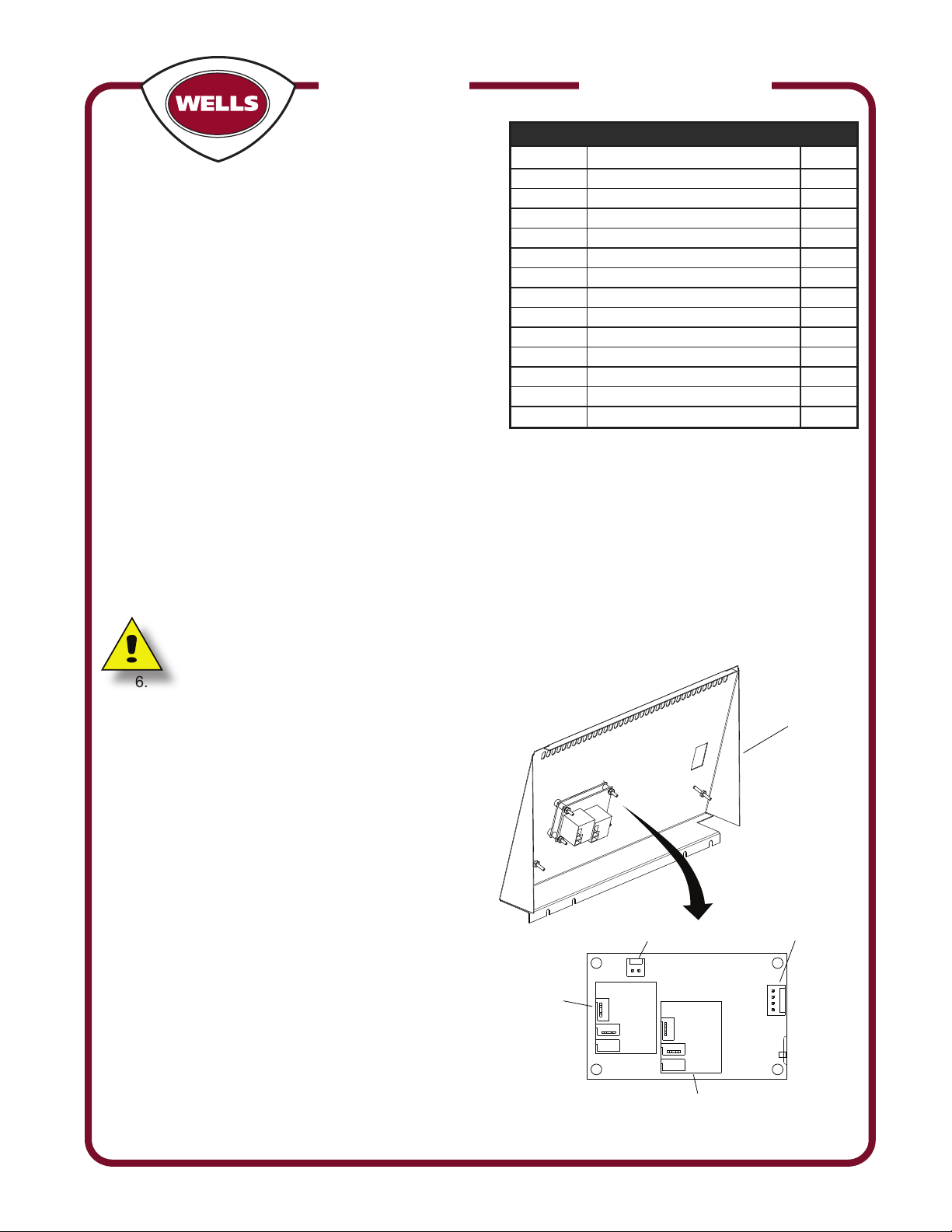
4 PIN CONNECTOR
THERMISTOR
HEATER
RELAY
BASKET
RELAY
2 PIN CONNECTOR
24 VOLT INPUT
N.C.N.O.
COM
N.C.N.O.
COM
Grounding
Stud
(2 Places)
IL2545a
WS-WL0334 Control Retrot Replacement
WFAE55FS & WVAE55FS
CONTROL REPLACEMENT
The kit has been designed to address replacing a
failed controller in a Wells Electric Open Frypot Fryer.
Unfortunately the new controller requires a new control
panel, thermistor, relay and wiring.
Please read these instructions thoughly before beginning these
process. This should be performed by a licensed Wells service
agent.
Part Number Description Quantity
2C-1810 WASHER 3/16 BURR STL NP 4
2C-2553 NUT 6-32 HEX STL NP 4
2E-307334 RELAY 240VAC 1
2E-49550 SWITCH ROCKER POWER WFAE 1
2J-Z16332 THERMISTOR 91K W/ LEADS 1
2J-Z16356 CONTROL CTT 1
2K-Z1530 SPACER 4
2K-Z16357 COMPRESSION FITTING 1
2M-Z16212 FACEPLATE CONTROLLER 55FC 1
2M-Z16330 INSTRUCTION SHEET 1
2M-Z16331 LABEL DIAGRAM 55FS SERIES 1
E7-Z16328 CONTROL PANEL 1
E7-Z16329 WIRE KIT CTT RETROFIT 1
Installation Instruction
1. Unit must be disconnected from power supply before service
2. Drain oil from fry kettle.
3. Remove front panel with control board.
4. Remove ground wires from front panel.
5. Remove power switch from old control panel and disconnect the associated wires from the
switch. (8A, 9A, 16, 24, 25, 26, 27, 28) Note: wires 24 & 28 non-ventless units only.
a. For ventless fryers the wires that need to be disconnected from the switch are 8A, 9A, 16, 40, 25,
26, 27 & 42.
Note: Audible alarm needs to be disconnected but should remain in place.
6. Remove and discard wires attached to multi
pin connectors from old control.
(10, 11, 12, 13, 22, 21, 19, 20)
7. Attach ground wires to new control panel.
8. Reinstall main power switch and associated
wiring (8A, 9A, 16, 24, 25, 26, 27, 28) into
replacement control panel.
a. If ventless model; the following wires need to
be re-attached 8A, 9A, 16, 40, 25, 26, 27 & 42.
9. Remove Basket lift solid state relays from
control housing rear panel & replace with new
relay 2E-307334.
10. Remove and discard old wires (23, 30, 31, 32
& 33) from the control housing rear panel.
11. Remove ring terminals from wires 17 & 18 and
replace with ¼” inch push on terminals.
12. Attach wire 17 to the N.O. terminal of the lift
relay on the new control board.
(see wiring diagram).
13. Attach wire 18 to the N.C. terminal of the lift
relay on the new control board.
(see wiring diagram).
2M-Z16330, Rev. A 130305 SV363
Page 2
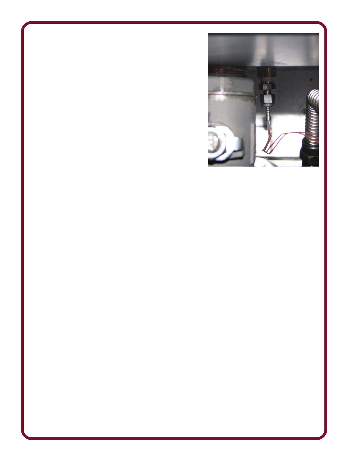
14. Usingteontapeonthethreadedconnections,
replace temperature probe assembly with new probe &
compression assemblies located in the bottom of the kettle.
(As shown here)
15. Connect temperature probe to the control board terminal
marked “J4”.
16. Remove surge suppressors (if present) from hybrid
contactor, high limit contactor, and control circuit
transformer.
17. Attach new wire assembly 12/13 to secondary on
transformer and power input connector “J3” on new board.
18. Attach new wire assembly 11A to hybrid relay terminal and
COM terminal on the new relay mounted to the wall of the
fryer. (see wiring diagram).
19. Attach wire 19 to the safety contactor and to the N.O.
terminal on the relay, mounted to the control housing rear
panel.
20. Attach new wire assembly 11 to COM terminal heater relay
mounted to center of the new board (see wiring diagram).
21. Attach the other end of new wire 11 to the 3/16 input terminal on the relay mounted on the wall of the
fryer.
22. Attach new wire 14A to the remaining input terminal on the new relay mounted on the wall of the
fryer (see wiring diagram) and to the safety contactor.
23. Attach the tandem end of the new wire assembly 30/23 to the COM terminal on the lift relay on the
control board (see wiring diagram).
24. Attach wire 23 to the high limit thermostat with wire 24 (Non-Ventless Units Only).
25. For ventless models 23 & 43 attach together at the high limit thermostat.
26. Attach wire 30 to the terminal of the transformer that corresponds to the nameplate voltage on the
fryer (208 or 240).
27. Attach the new control panel to the fryer body.
28. Connectpowertothefryerandllthekettlewithoil.
29. Checkforleaksattheprobetting.
2M-Z16330, Service Instructions 55FS Series Control Retrot
Page 3

TIME
PROG
HEAT
BASKET
DOWN
TEMP
PROG
4
3
21
FRYER IS BELOW COOKING TEMPERATURE
FRYER HAS REACHED COOKING TEMPERATURE
COOK CYCLE HAS BEEN COMPLETED
FRYER HAS EXCEEDED COOKING TEMPERATURE
DISPLAY DESCRIPTIONS
New Board Operating Instructions
Program Time:
1. Press and hold the “TIME” program key 3
seconds. Display will read “Prog”
2. Select a key 1 – 4 to program.
3. Adjust time up or down using keys 1 & 4.
4. Press program key to accept (control is now
ready for pre-alarm time set (optional)
5. Adjust pre-alarm “UP” or “DOWN” using keys 1
and 4, or
6. Press “PROG” key to accept (Default Value “0”)
7. Select Another key to program and repeat steps
2 – 6.
8. Press “TIME PROG” key to exit program mode.
Program Temperature:
1. Press and hold the “TEMP PROG” key 3
seconds. Display will read “Prog”.
2. Select either key 1 or 4 to program.
3. Choose “C” (Celsius) or “F” (Fahrenheit) using
keys 1 or 4.
4. Press “TEMP PROG” key to accept.
5. Set temperature using keys 1 and 4, DO NOT EXCEED 375°F (190°C).
6. Press “TEMP PROG” to accept.
7. Press “TEMP PROG” key again to exit program mode.
Display Descriptions
Lo Fryer is below cooking temperature
rEdY Fryer has reached cooking temperature
2M-Z16330, Service Instructions 55FS Series Control Retrot
done cook cycle has been completed
Hi Fryer has exceeded cooking temperature
Page 4

55FS SERIESLABEL, DIAGRAM 55FS CTT RETROFIT
2M-Z16331a
NOTE: -WIRE NUMBERS 16, 17 AND 18 ARE ROUTED THRU
A 3/8 INCH FLEXIBLE CONDUIT.
-WIRE NUMBERS 26, 27, AND 36 ARE ROUTED THRU
A 3/8 INCH FLEXIBLE CONDUIT.
17
RED
17
8500W ELEMENT
8500W ELEMENT
24V
208V
240V
13
12
16
16
25
24
WHITE
18
EXTERNAL INTERLOCK
TERMINAL BLOCK
(REMOVE JUMPER
WHEN EXTERNAL
CONTROL IS USED)
CONTROLLER
TRANSFORMER
GREEN
34
27
26
27
26
FILTER
PUMP
MAIN
TERMINAL
BLOCK
HYBRID RELAY
1L1
1L2
1L3
1L1
1L2
1L3
SAFETY
CONTACTOR
1
2
3
1
2
3
1
2
3
6
5
4
15
C
POWER
SWITCH
9
14
BASKET LIFT
ACTUATOR
LIMIT SWITCHES
INSIDE MTR HSG
BLACK
7
8
28
30
10
11A
(DN)
(UP)
(COM)
FUSE
15A MAX
FUSE
15A MAX
L3
L2
L1
JUMPER
24
HI LIMIT
THERMOSTAT
23
14
8A
28
9A
THERMISTOR
J4
24V AC
COM
NO
NC
COM
NO
NC
LIFT
TEMP
18
GREEN
COM
NO
11
14A
19
BLD'G ALARM RELAY
(2&4) BEHIND REAR
BOTTOM COVER ON
RIGHT HAND SIDE OF
BOTTOM PANEL.
NO
COM
NC
3
4
2
5
1
58
58
220V 60HZ
BUZZER
40
57
BAFFLE FILTER
MAGNET OPERATED
SWITCH
HEPA FILTER
MAGNET OPERATED
SWITCH
WIRE
NUT(2)
41
42
BROWN
56
BLACK
RED
1/4 INS
FEMALE
1/4 INS
MALE
40
54
41
52
44
44
45
M
1/4 INS
FEMALE(2)
VENTILATOR
POWER
LIGHT
(GREEN)
53
CHECK
FILTER
LIGHT
(AMBER)
REPLACE
FILTER
LIGHT
(AMBER)
SERVICE
REQUIRED
LIGHT
(RED)
NC
C
2
1
3
NO
C
1/4 INS
MALE
1/4 INS
FEMALE
AIR FLOW
VACUUM
SWITCH
(LARGE)
BLOWER
MOTOR
REPLACE
FILTER
VACUUM
SWITCH
(SMALL)
INTERVAL TIMER
50
44
45
46
47
48
49
56
55
44
41
51 51
HOOD
HOOD
UPPER CONTROL BOX
UPPER CONTROL BOX
1/4 INS
MALE(2)
42
43
59
59
M-S
43
FOR VENTLESS MODELS ONLY
ALTERNATE WIRING FOR SINGLE PHASE OPERATION
NOT UL LISTED
ON SINGLE PHASE
ALTERNATE WIRING FOR 380-415V
5670W ELEMENT
5670W ELEMENT
1L1
1L3
1L1
1L3
1
3
1
3
1
3
5
4
L3
L2
L1
1Ø, 208V OR 240V, 11.3KW
8
7
4
5
6
3
2
1
TERMINAL
BLOCK
JUMPER
L1
L2
L3
N
WIRES 40,41,42, AND 43 ONLY NECESSARY ON VENTLESS MODELS WVAE
WIRES 24 AND 28 ARE ONLY USED ON NON VENTLESS MODELS WFAE
414242
240
47
4848
L3
L2L1
AMPS
FRYER RATING
VOLTS
208
50-60 HZ
WFAE55FS
3Ø, 208V,17KW
WVAE55FS
3Ø, 208V,17KW
-----47-----
*1Ø, 240
-----
56
-----
*1Ø, 208
WFAE55FS
3Ø, 380-415V, 17KW
* NOT UL LISTED
ON SINGLE PHASE
1Ø, 208V OR 240V, 11.3KW
3Ø, 380
N
-----
-----
-----
-----
24 24 24
5
2M-Z16330, Service Instructions 55FS Series Control Retrot
 Loading...