

Page 1
WELLS MANUFACTURING
10 Sunnen Dr., St. Louis, MO 63143
telephone: 314-678-6314
fax: 314-781-2714
www.wellsbloomfield.com
OWNERS MANUAL
OPEN FRYPOT
with AUTO-LIFT
(FRYER SECTION ONLY)
WFAE55FC
363
ELECTRIC
55# FRYER
MODEL
WFAE55F
WVAE55F
WVAE55FC
(FRYER SECTION ONLY)
WITH OR WITHOUT
OPTIONAL FILTER WAND
Includes
INSTALLATION
USE & CARE
EXPLODED VIEW
WFAE55F
WARNING:
Improper installation, adjustment, alteration, service or maintenance can cause
property damage, injury or death. Read the installation and operating instructions
thoroughly before installing, using or servicing this equipment.
IMPORTANT: DO NOT DISCARD THIS MANUAL
This manual is considered to be part of the appliance and is to be given to the OWNER or
MANAGER of the restaurant, or to the person responsible for TRAINING OPERATORS of
this appliance. Additional manuals are available from your WELLS DEALER.
PARTS LIST
WIRING DIAGRAM
THIS MANUAL MUST BE READ AND UNDERSTOOD BY ALL PERSONS USING OR
INSTALLING THIS APPLIANCE. Contact your WELLS DEALER if you have any
questions concerning installation, operation or maintenance of this equipment.
p/n 2M-Z16530 Rev. B M363 160609
Page 2

LIMITED WARRANTY STATEMENT
Unless otherwise specied, all commercial cooking
equipment manufactured by Wells Manufacturing is
warranted against defects in materials and workmanship for a
period of one year from the date of original installation or 18
months from the date of shipment from our factory, whichever
comes rst, and is for the benet of the original purchaser
only.
THIS WARRANTY IS THE COMPLETE AND ONLY
WARRANTY, EXPRESSED OR IMPLIED IN LAW
OR IN FACT, INCLUDING BUT NOT LIMITED TO,
WARRANTIES OF MERCHANTABILITY OR FITNESS
FOR ANY PARTICULAR PURPOSE, AND/OR FOR
DIRECT, INDIRECT OR CONSEQUENTIAL DAMAGES
IN CONNECTION WITH WELLS MANUFACTURING
PRODUCTS. This warranty is void if it is determined
that, upon inspection by an authorized service agency,
the equipment has been modied, misused, misapplied,
improperly installed, or damaged in transit or by re, ood or
act of God. It also does not apply if the serial nameplate has
been removed, or if service is performed by unauthorized
personnel. The prices charged by Wells Bloomeld for its
products are based upon the limitations in this warranty.
Seller’s obligation under this warranty is limited to the repair
of defects without charge by a Wells Manufacturing factory
authorized service agency or one of its sub-service agencies.
This service will be provided on customer’s premises for
non-portable models. Portable models (a device with a cord
and plug) must be taken or shipped to the closest authorized
service agency, transportation charges prepaid, for service.
In addition to restrictions contained in this warranty, specic
limitations are shown in the Service Policy and Procedure
Guide. Wells Manufacturing authorized service agencies are
located in principal cities. This warranty is valid in the United
States and Canada and void elsewhere. Please consult your
classied telephone directory, your foodservice equipment
dealer or contact:
Wells Manufacturing
10 Sunnen Dr., St. Louis MO 63143 USA
phone (314) 678-6314 or fax (314) 781-2714
for information and other details concerning warranty.
SERVICE POLICY AND PROCEDURE GUIDE and ADDITIONAL WARRANTY EXCLUSIONS
1. Resetting of safety thermostats, circuit breakers, over
load protectors, and/or fuse replacements are not
covered by this warranty unless warranted conditions
are the cause.
2. All problems due to operation at voltages or phase
other than specied on equipment nameplates are not
covered by this warranty. Conversion to correct voltage
and/or phase must be the customer’s responsibility.
3. All problems due to electrical connections not made
in accordance with electrical code requirements and
wiring diagrams supplied with the equipment are not
covered by this warranty.
4. Replacement of items subject to normal wear, to
include such items as knobs, light bulbs; and, normal
maintenance functions including adjustments of
thermostats, adjustment of micro switches and
replacement of fuses and indicating lights are not
covered by warranty.
5. Damage to electrical cords and/or plug due to exposure
to excessive heat are not covered by this warranty.
6. Full use, care, and maintenance instructions supplied
with each machine. Noted maintenance and
preventative maintenance items, such as servicing
and cleaning schedules, are customer responsibility.
Those miscellaneous adjustments noted are customer
responsibility. Proper attention to preventative
maintenance and scheduled maintenance procedures
will prolong the life of the appliance.
7. Travel mileage is limited to sixty (60) miles from an
Authorized Service Agency or one of its sub-service
agencies.
8. All labor shall be performed during regular working
hours. Overtime premium will be charged to the buyer.
9. All genuine Wells replacement parts are warranted
for ninety (90) days from date of purchase on nonwarranty equipment. This parts warranty is limited only
to replacement of the defective part(s). Any use of nongenuine Wells parts completely voids any warranty.
10. Installation, labor, and job check-outs are not
considered warranty and are thus not covered by this
warranty.
11. Charges incurred by delays, waiting time or operating
restrictions that hinder the service technician’s ability
to perform service are not covered by warranty. This
includes institutional and correctional facilities.
SHIPPING DAMAGE CLAIM PROCEDURE
NOTE: For your protection, please note that equipment
in this shipment was carefully inspected and packaged
by skilled personnel before leaving the factory. Upon
acceptance of this shipment, the transportation company
assumes full responsibility for its safe delivery.
IF SHIPMENT ARRIVES DAMAGED:
1. VISIBLE LOSS OR DAMAGE: Be certain that any
visible loss or damage is noted on the freight bill or
express receipt, and that the note of loss or damage is
signed by the delivery person.
2. FILE CLAIM FOR DAMAGE IMMEDIATELY:
Regardless of the extent of the damage.
3. CONCEALED LOSS OR DAMAGE: if damage is
unnoticed until the merchandise is unpacked, notify the
transportation company or carrier immediately, and le
“CONCEALED DAMAGE” claim with them. This
should be done within fteen (15) days from the date
the delivery was made to you. Be sure to retain the
container for inspection.
Wells Manufacturing cannot assume liability for damage or
loss incurred in transit. We will, however, at your request,
supply you with the necessary documents to support your
claim.
xi
363 2M-Z16530 Owners Manual WFAE-55F/FC Free-Standing Electric Fryer
363 2M-Z16530 Owners Manual WFAE-55F/FC Free-Standing Electric Fryer
Page 3
TABLE OF CONTENTS
WARRANTY xi
SPECIFICATIONS 1
WFAE-55F FEATURES & OPERATING CONTROLS 2
WFAE-55FS FEATURES & OPERATING CONTROLS 4
PRECAUTIONS & GENERAL INFORMATION 6
AGENCY LISTING INFORMATION 7
INSTALLATION 8
PREPARATION PRIOR TO OPERATION 10
OPERATION
WFAE-55F (MANUAL CONTROLS) 15
WFAE-55FC (SOLID STATE CONTROLS) 16
CLEANING 18
MAINTENANCE INSTRUCTIONS
FILTER SYSTEM 21
DISCARDING USED OIL 24
CRADLE LIFT & ROLLERS 26
TROUBLESHOOTING SUGGESTIONS 28
EXPLODED VIEW & PARTS LIST 30 - 45
WIRING DIAGRAM 46
PARTS & SERVICE 48
CUSTOMER SERVICE DATA 48
INTRODUCTION
Thank You for purchasing this
Wells Manufacturing appliance.
Proper installation, professional
operation and consistent
maintenance of this appliance will
ensure that it gives you the very
best performance and a long,
economical service life.
This manual contains the
information needed to properly
install this appliance, and to use
and care for the appliance in
a manner which will ensure its
optimum performance.
SPECIFICATIONS
DIMENSIONS
CAPACITIES
VOLTAGE
REQUIREMENTS
POWER
CONSUMPTION
AMPERAGE 47.8 amps per leg (3ø) 43.0 amps per leg (3ø)
363 2M-Z16530 Owners Manual WFAE-55F/FC Free-Standing Electric Fryer
363 2M-Z16530 Owners Manual WFAE-55F/FC Free-Standing Electric Fryer
Wide Deep High
15.70” 37.38” 48.94”
Cooking Oil (Liquid Shortening
Only)
Chicken (Fresh) 30 13
Chicken (Frozen) 25 11
ELECTRICAL SPECIFICATIONS
DOMESTIC EXPORT (EU)
208 VAC 240VAC
NOTE: Shipped from factory 3ø.
THIS FRYER IS NOT APPROVED FOR CONVERSION TO 1ø
9,000 watts 9,000 watts 9.300 watts
Lbs. Kg.
55 25
380-415V
L1 = 27.0 amps
L2 = 26.5 amps
L3 = 26.5 amps
N = 0.5 amps
3NAC
1
Page 4
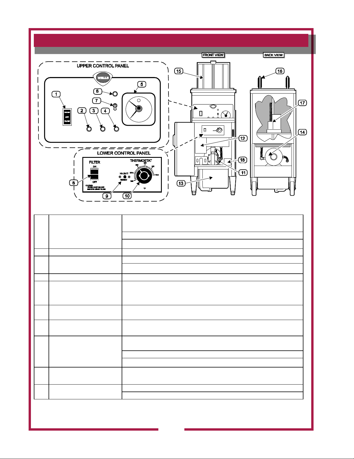
FEATURES & OPERATING CONTROLS
Fig. 1 WFAE-55F Features & Operating Controls
FRYER position energizes the fryer and power light; de-energizes lter pump.
POWER SWITCH
1
(FRYER-OFF-FILTER)
Heating elements energized and regulate to setting on CONTROL thermostat (8).
OFF position de-energized fryer and lter pump.
FILTER position de-energizes fryer; energizes lter pump switch (6).
2 POWER LIGHT (amber) Glows to indicate fryer is energized.
Glows to indicate heating element energized;
3 HEAT LIGHT (amber)
Off when oil temperature reaches setting on control thermostat (8).
4 COOK LIGHT (amber) Glows to indicate COOK LEVER in cook position.
Controls LIFT CRADLE and BUZZER. Start TIMER by pressing red button at center
5 TIMER
of knob. Lift CRADLE will lower. Pointer indicates time remaining. When time
reaches “0” BUZZER sounds and LIFT CRADLE raises.
6 BUZZER LIGHT (amber)
7 BUZZER SWITCH
When lit, indicates BUZZER SWITCH (item 7) is turned ON and BUZZER CIRCUIT
is active
Activates BUZZER CIRCUIT. When ON will sound BUZZER anytime TIMER is at
“0”. Turn switch OFF or activate timer to silence buzzer.
ON position energizes lter pump and causes oil in reservoir (10) to be pumped
FILTER PUMP SWITCH
8
(ON-OFF)
back into frypot.
OFF position de-energizes lter pump.
NOTE: power switch (1) must be in FILTER position for lter pump to operate.
9 HI-LIMIT THERMOSTAT
TEMPERATURE
10
CONTROL THERMOSTAT
Provides over-temperature protection by de-energizing HEATING ELEMENTS
should oil temperature exceed factory pre-set limits.
Controls oil temperature. Range: 250ºF (121ºC)
375ºF (191ºC)
IL2553
363 2M-Z16530 Owners Manual WFAE-55F/FC Free-Standing Electric Fryer
2
Page 5

FEATURES & OPERATING CONTROLS (continued)
IL2554a
WARNING: FIRE HAZARD / HOT OIL
The HI-LIMIT THERMOSTAT is a FIRE PROTECTION DEVICE.
If tripping persists, clean debris from the space between the
hi-limit bulb and the element to enhance oil flow and facilitate reset.
Otherwise, contact your authorized Wells Service Agent for repairs.
DO NOT ATTEMP TO BYPASS OR HOLD IN THE BUTTON OF
THE HI-LIMIT THERMOSTAT. A SERIOUS FIRE MAY RESULT.
Opens and closes the drain valve:
11 DRAIN VALVE LEVER
12 POWER OUTLET BOX Electrical service connection terminal block located here.
13 OIL FILTER RESERVOIR
FILTER PUMP MOTOR Filter pump motor is equipped with an overheating protection device.
14
RESET BUTTON (located at
rear of motor)
Turn counterclockwise (vertical) to OPEN
Turn clockwise (horizontal) to CLOSE
Collects oil from frypot for ltering or disposal. Holds lter screen, lter paper & lter
paper holder.
RESET must be performed manually. Allow motor to cool for approx. 30 min, then
rmly press the red button.
IL2555
15 LIFT CRADLE
Lowers fry basket into frypot during cook cycle. Automatically raises from frypot at
end of cook cycle
16 FRY BASKET Holds product to be cooked.
17 LIFT MOTOR
18 DRIP PAN
Raises/lowers LIFT CRADLE. Accessible for lubrication thru access plate in rear
panel.
Collects liquids that accumulate on top of fryer section of Ventilator Hood models
(WVAE-…).
For units equipped with OPTIONAL FILTER WAND
W1 HEATER INTERLOCK SWITCH Disables heating element any time drain valve is not closed.
W2 3-WAY VALVE HANDLE
W3
363 2M-Z16530 Owners Manual WFAE-55F/FC Free-Standing Electric Fryer
QUICK DISCONNECT MALE
FITTING
HORIZONTAL directs output of lter pump to lter wand.
VERTICAL directs output of iter pump to frypot.
Filter wand connects to this tting.
3
Page 6
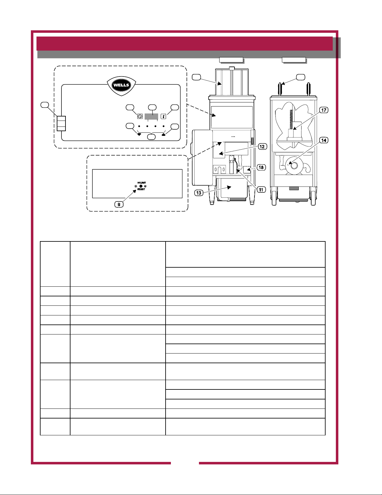
FEATURES & OPERATING CONTROLS
UPPER CONTROL PANEL
LOWER CONTROL PANEL
FRONT VIEW BACK VIEW
15
1
16
IL2581
IL2544
IL2544
TIME
PROG
HEAT
BASKET
DOWN
TEMP
PROG
4
3
21
FRYER IS BELOW COOKING TEMPERATURE
FRYER HAS REACHED COOKING TEMPERATURE
COOK CYCLE HAS BEEN COMPLETED
FRYER HAS EXCEEDED COOKING TEMPERATURE
done
rEdY
Hi
DISPLAY DESCRIPTIONS
Lo
TO START A TIMING CYCLE
PRESS A PRODUCT KEY 1-4
TO RESPOND TO A DONE ALARM
PRESS THE ACTIVE PRODUCT KEY 1-4
TO STOP A TIMING CYCLE
PRESS AND HOLD THE ACTIVE PRODUCT KEY 3 SECONDS
TO VIEW ACTUAL TEMPERATURE
PRESS THE TEMP KEY (FIRST DIGIT OF DISPLAY WILL BE “A”)
TO VIEW SET TEMPERATURE
PRESS THE TEMP KEY 2 TIMES (FIRST DIGIT OF DISPLAY WILL BE “P”)
OPERATING INSTRUCTIONS
TO PROGRAM TIME
1. PRESS AND HOLD THE TIME PROG KEY 3 SECONDS
DISPLAY WILL READ “Prog”
2. SELECT A KEY 1-4 TO PROGRAM
3. ADJUST TIME UP OR DOWN USING KEYS 1 AND 4
4. PRESS PROG KEY TO ACCEPT
CONTROL IS NOW READY FOR PRE ALARM TIME SET (OPTIONAL)
5. ADJUST PRE ALARM UP OR DOWN USING KEYS 1 AND 4, OR
6. PRESS PROG KEY TO ACCEPT (DEFAULT VALUE “0”)
7. SELECT ANOTHER KEY TO PROGRAM AND REPEAT STEPS 2-6
8. PRESS TIME PROG KEY TO EXIT PROGRAM MODE
TO PROGRAM TEMPERATURE
1. PRESS AND HOLD THE TEMP PROG KEY 3 SECONDS
DISPLAY WILL READ “Prog”
2. SELECT EITHER KEY 1 OR 4 TO PROGRAM
3. CHOOSE C (CELSIUS) OR F (FAHRENHEIT) USING KEYS 1 OR 4
4. PRESS TEMP PROG KEY TO ACCEPT
5. SET TEMPERATURE USING KEYS 1 AND 4 * DO NOT EXCEED 375F/190C
6. PRESS TEMP PROG KEY TO ACCEPT
7. PRESS TEMP PROG KEY AGAIN TO EXIT PROGRAM MODE
FRYER
OFF
FILTER
2
6
7
3
5
4
Fig. 1 WFAE-55FC Features & Operating Controls
FRYER position energizes the fryer and power light; de-energizes
lter pump. Heating elements energized and regulate to setting on
1
POWER SWITCH
(FRYER-OFF-FILTER)
CONTROL thermostat (8).
OFF position de-energized fryer and lter pump.
FILTER position de-energizes fryer; energizes lter pump switch.
2 TIME KEY Used to check and set menu times
3 TEMP KEY Used to check and set cooking temperature
4 DIGITAL READOUT LED display of various data and functions
5 UP ARROW KEY Used to raise FRY BASKET and to increase program settings
6 DOWN ARROW KEY Used to lower FRY BASKET and to decrease program settings
Used to start a menu time/temp cook cycle
7 MENU KEYS
9 HI-LIMIT THERMOSTAT
11 DRAIN VALVE LEVER
12 POWER OUTLET BOX Electrical service connection terminal block located here.
13 OIL FILTER RESERVOIR
Keys 1 thru 6 are programmable for time and temperature
Key 7 is available for individually set time/temp cook cycles
Provides over-temperature protection by de-energizing HEATING
ELEMENTS should oil temperature exceed factory pre-set limits.
Opens and closes the drain valve:
Turn counterclockwise (vertical) to OPEN
Turn clockwise (horizontal) to CLOSE
Collects oil from frypot for ltering or disposal. Holds lter screen,
lter paper & lter paper holder.
363 2M-Z16530 Owners Manual WFAE-55F/FC Free-Standing Electric Fryer
4
Page 7
FEATURES & OPERATING CONTROLS (continued)
WARNING: FIRE HAZARD / HOT OIL
The HI-LIMIT THERMOSTAT is a FIRE PROTECTION DEVICE.
If tripping persists, clean debris from the space between the
hi-limit bulb and the element to enhance oil flow and facilitate reset.
Otherwise, contact your authorized Wells Service Agent for repairs.
DO NOT ATTEMP TO BYPASS OR HOLD IN THE BUTTON OF
THE HI-LIMIT THERMOSTAT. A SERIOUS FIRE MAY RESULT.
FILTER PUMP MOTOR Filter pump motor is equipped with an overheating protection device.
14
15 LIFT CRADLE
16 FRY BASKET Holds product to be cooked.
17 LIFT MOTOR
18 DRIP PAN
RESET BUTTON (located at rear of
motor)
RESET must be performed manually. Allow motor to cool for approx.
30 min, then rmly press the red button.
Lowers fry basket into frypot during cook cycle. Automatically raises
from frypot at end of cook cycle
Raises/lowers LIFT CRADLE. Accessible for lubrication thru access
plate in rear panel.
Collects liquids that accumulate on top of fryer section of Ventilator
Hood models (WVAE-…).
IL2555
363 2M-Z16530 Owners Manual WFAE-55F/FC Free-Standing Electric Fryer
5
Page 8
PRECAUTIONS AND GENERAL INFORMATION
DANGER:
BURN HAZARD
Cooking oil in this appliance
operates at very high
temperatures. Contact with
hot oil can cause severe
injury or death. Wear
appropriate heat-protective
clothing when operating or
servicing this appliance.
WARNING:
BURN HAZARD
DO NOT allow water or ice
to contact hot oil. DO NOT
attempt to cool the oil with
water or ice. The water
will boil violently, causing
hot oil to foam and splatter.
Contact with splattering or
foaming hot oil will cause
severe burns.
WARNING:
SLIP AND FALL
HAZARD
Spilled cooking oil is very
slippery and can cause falls.
Clean up oil spills promptly.
CAUTION:
BURN HAZARD
Exposed surfaces can be hot
to the touch and may cause
burns.
This appliance is intended for use in commercial establishments only.
This appliance is intended to prepare food for human consumption.
No other use is recommended or authorized by the manufacturer or its
agents.
DO NOT open any panel that requires the use of tools for access. Live
electric circuits may be exposed by opening such panels. Opening
access panels must be performed by an Authorized Service Agent only.
This appliance is equipped with an oil ltration system designed to lter
hot liquid shortening only. Water, cleaning agents and/or other liquids
will contaminate the oil and may damage the lter pump.
Operators of this appliance must be familiar with the appliance use,
limitations and associated restrictions. Operating instructions must be
read and understood by all persons using or installing this appliance.
Cleanliness of this appliance is essential to good sanitation. Read and
follow all included cleaning instructions and schedules to ensure the
safety of the food product.
DO NOT submerge any part of this appliance in water unless
specically instructed to do so. This appliance is not jet stream
approved. DO NOT direct water jet or steam jet at this appliance,
nor at any control. DO NOT splash or pour water on, in or over any
controls. DO NOT wash area around this appliance with water jet. Any
part which has become wet must be thoroughly dried before use.
Cooking oil will be very hot when in use. Contact will cause severe
injury, and can cause blindness or death. Wear appropriate heatprotective clothing when operating or servicing this appliance.
This appliance must be operated with the supplied legs and casters
properly installed
The technical content of this manual, including any parts breakdown
illustrations and/or adjustment procedures, is intended for use by
qualied technical personnel only.
Any procedure which requires the use of tools must be performed by a
qualied technician.
This manual is considered to be a permanent part of the appliance.
This manual and all supplied instructions, diagrams, schematics,
parts breakdown illustrations, notices and labels must remain with the
appliance if it is sold or moved to another location.
CAUTION:
HEALTH HAZARD
Old cooking oil can be a
breeding ground for bacteria.
Clean and sanitize exterior
surfaces of fryer regularly.
363 2M-Z16530 Owners Manual WFAE-55F/FC Free-Standing Electric Fryer
6
Page 9
AGENCY LISTING INFORMATION
®
C
This appliance conforms to NSF Standard 4 for sanitation only if
installed in accordance with the supplied Installation Instructions and
maintained according to the instructions in this manual.
Domestic fryers are and listed under UL File E6070 for 208V
and 240V.
Export (European) fryers comply with standards
for 380-415V 3NAC.
STD 4
E6070
E6070
363 2M-Z16530 Owners Manual WFAE-55F/FC Free-Standing Electric Fryer
7
Page 10

INSTALLATION
NOTE: DO NOT discard
the carton or other packing
materials until you have
inspected the appliance for
hidden damage and tested it
for proper operation. Refer to
SHIPPING DAMAGE CLAIM
PROCEDURE on the inside
front cover of this manual.
WARNING:
FIRE HAZARD
Do not store gasoline or
any other ammable or
combustible material near this
appliance.
The area where the fryer is
installed must be kept clear of
combustibles and ammables.
This includes mops, rags,
grease, wrapping paper and
electric cords.
Installation and startup must
be performed by a Wells
Manufacturing Authorized
Service Agency.
IMPORTANT:
Certain jurisdictions require
fryers to be restrained
with a TETHER or other
approved restraint device.
It is the responsibility of
the installer to check with
the AUTHORITY HAVING
JURISDICTION in order to
ascertain the applicability
of this requirement to THIS
SPECIFIC INSTALLATION.
Installer must complete the
WARRANTY REGISTRATION
and FRYER CHECKOUT
form, and record the details of
the particular installation on
the CUSTOMER SERVICE
DATA form in this manual.
UNPACKING & INSPECTION
Carefully remove the appliance from the carton. Remove all protective
plastic lm, packing materials and accessories from the appliance
before connecting performing any installation procedure.
Carefully read all instructions in this manual and the Installation
Instruction Sheet packed with the appliance before starting any
installation.
Read and understand all labels and diagrams attached to the
appliance.
Carefully account for all components and accessories before discarding
packing materials. Store all accessories in a convenient place for later
use.
COMPONENTS
1 ea. FILTER RESERVOIR
1 ea. FILTER LEAF
4 ea. OIL FILTER SUCTION TUBE O-RINGS
1 ea. LIFT CRADLE
1 ea. FRY BASKET
1 ea. FRYPOT COVER
ACCESSORIES
1 ea. LITERATURE PACKAGE
1 pk. FILTER POWDER
2 ea. HIGH TEMPERATURE BRUSHES
1 ea. CLEANOUT DOWEL (wood rod)
1 ea. 1-1/4 NPT STREET ELBOW
1 ea. 1-1/4 NPT x 12” DRAIN PIPE
SETUP
It is the responsibility of the installer to verify that this fryer installation
is in compliance with local code authorities and with the specications
listed in this manual.
Certain local or state codes require fryers to be restrained with a tether
or other approved restraint device. It is the responsibility of the installer
to check with the authority having jurisdiction, in order to ascertain the
applicability of this requirement to this specic fryer installation.
Setup the fryer only on a rm, level, non-combustible surface. Verify
local codes for requirements. Concrete, tile, terrazzo or metal surfaces
are recommended. Metal or tile over combustible material may not
meet code for non-combustible surfaces.
Verify that the unit sits rmly on BOTH CASTERS AND BOTH LEGS.
With the adjustable legs, adjust as required to level the appliance.
Both legs and both casters must be adjusted to rmly contact the oor
in order to prevent tipping.
Refer to the Installation Instruction Sheet for required clearances.
Maintain required clearances between the appliance and adjacent
combustible surfaces.
363 2M-Z16530 Owners Manual WFAE-55F/FC Free-Standing Electric Fryer
8
Page 11
INSTALLATION (continued)
ELECTRICAL INSTALLATION
Refer to the nameplate on the front of the fryer and to the specications
listed on page 1 of this manual. Verify that electric service voltage,
phase and amperage capacity meet or exceed these specications.
Field wiring must be no less than 4 ga. solid copper wire, rated for at
lease 90ºC.
Fryers are shipped from the factory wired for 3ø. Fryer is not approved
for conversion to single phase.
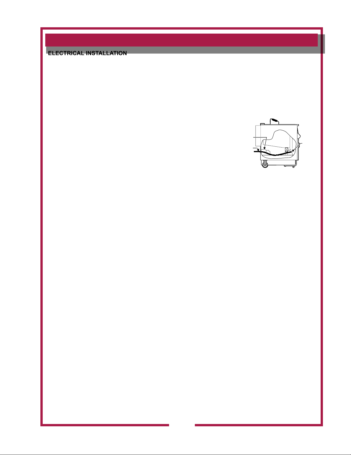
IMPORTANT:
Field wiring must be routed and secured away from the FRYPOT,
TUBING and FILTER PUMP MOTOR. Field wiring must be congured
to allow access to the rear of fryer for cleaning and access to the lter
pump motor RESET BUTTON.
IMPORTANT:
Electric installation of this
appliance must be performed
by a licensed electrician.
Installation must conform
to the requirements of local
codes and ordinances, and
to the requirements of the
National Electrical Code.
FILTER
PUMP &
MOTOR
POWER
CORD
FRYPOT
STRAIN
RELIEF
FITTING
Fig. 2 Field Wiring
IMPORTANT:
This appliance is rated for
3ø electric service only, and
is not UL approved for single
phase operation.
DO NOT convert this
appliance to single phase.
Doing so will void the
warranty and invalidate the
UL listing.
IL2556
363 2M-Z16530 Owners Manual WFAE-55F/FC Free-Standing Electric Fryer
9
Page 12
PREPARATION PRIOR TO OPERATION
WVAE55F / FC PRE-CLEANING PROCEDURE
WARNING:
BURN HAZARD
TURN THERMOSTAT TO LOWEST TEMPERATURE SETTING
(FULLY CONTERCLOCKWISE)
USE ONLY LOW-FOAMING COMMERCIAL FRYER CLEANSER.
CAREFULLY FOLLOW CLEANSER INSTRUCTIONS AND WARNINGS.
DO NOT LEAVE FRYER UNATTENDED
WHILE BOILING OUT FRYPOT
WHEN WATER BEGINS FOAMING,
BE PREPARED TO TURN POWER SWITCH OFF.
Boiling water and splatter can result in moderate to serious injury.
IL2557
Prior to leaving the factory,
each fryer is tested for proper
operation. Oil residue must be
cleaned from the frypot before
lling it with fresh oil.
IMPORTANT:
Use a LOW-FOAMING
COMMERCIAL fryer cleanser
only.
Press POWER SWITCH OFF.
Close DRAIN VALVE (lever horizontal).
Fill FRYPOT with 4 gallons of cold water.
Press POWER SWITCH to FRYER.
When water comes to a full boil, press POWER SWITCH
OFF. When boiling ceases, slowly add and stir in the LOW
FOAMING COMMERCIAL FRYER CLEANSER. Using the HIGH
TEMPERATURE BRUSH supplied with the fryer, stir until the cleanser
is completely dissolved.
Press POWER SWITCH to FRYER. When the water begins to boil,
press POWER SWITCH OFF. When the boiling subsides, again press
POWER SWITCH to FRYER. Repeat this procedure continuously for
ve (5) minutes.
Press POWER SWITCH OFF. Allow the solution to cool to 120ºF or
less.
Place a suitable METAL container under the drain valve. Open DRAIN
VALVE (lever vertical) to drain the cleaning solution.
NOTE: Drain no more than 4” at a time into the container to prevent
splashing and spilling. Dispose of used solution as required by local
ordinances.
Rinse frypot with clean water. Dry with a soft clean cloth.
10
363 2M-Z16530 Owners Manual WFAE-55F/FC Free-Standing Electric Fryer
Page 13

PREPARATION PRIOR TO OPERATION (continued)
IL2558
RETAINING NUT
ROLLER
IL2559
FILTER RAIL “A”
FILTER RAIL “B”
FILTER
RESERVOIR
ASSEMBLED FILTER LEAF
(spout with O-RING inserts
into drain opening)
RESERVOIR
ASSEMBLY
CROSS-SECTION VIEW
“O” RING
Note: “O” RING
SPARE
“O” RING
STORAGE FOR 3
SPARE “O” RING
“O” RING IN
“O” RING GROOVE
UPPER
FILTER SCREEN
LOWER
FILTER SCREEN
SEPARATOR
IL2560
IMPORTANT:
Serious damage to the frypot
will result if the rollers are
missing or do not rotate freely.
Examine the CRADLE ROLLERS. Adjust or tighten as required.
Lubricate the rollers with vegetable oil.
DO NOT operate the fryer unless CRADLE ROLLERS are in place
and rotating freely.
Install LIFT CRADLE onto CRADLE PIVOT. Set FRY BASKET on
LIFT CRADLE.
363 2M-Z16530 Owners Manual WFAE-55F/FC Free-Standing Electric Fryer
Install FILTER LEAF into FILTER RESERVOIR.
SUCTION TUBE O-RINGS are shipped from the factory installed on
SUCTION TUBE; Examine to verify one O-RING is in the groove
closest to the end of the tube.
Install assembled FILTER RESERVOIR into fryer. O-RING for the
lter reservoir suction tube, and up to three spare O-RINGS, are
stored as shown above.
11
Page 14
PREPARATION PRIOR TO OPERATION (continued)
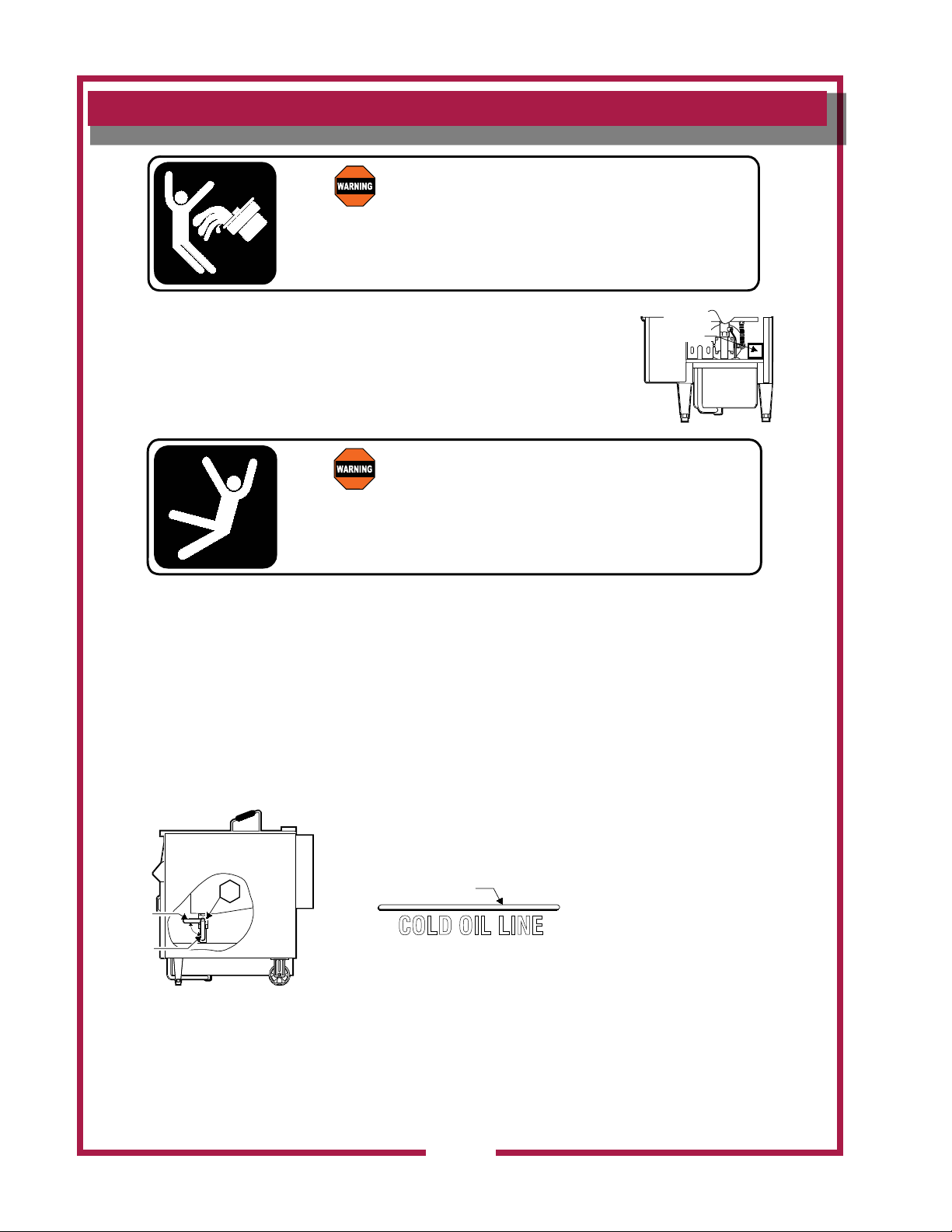
WARNING: SLIP/FALL HAZARD
DO NOT OPERATE UNLESS DRIP PAN IS INSTALLED.
Oil will drip on the floor and slips/falls will result.
Death or serious injury may result from slipping and falling in spilled oil.
IL2561
WARNING: SLIP/FALL HAZARD
CLOSE DRAIN VALVE BEFORE FILLING WITH OIL
Unless drain valve is closed, oil poured into kettle will drain into
reservoir or onto the floor. Oil spill may occur.
Death or serious injury may result from slipping and falling in spilled oil.
IL2563
CLOSED
FILL TO THIS LINE WITH
ROOM TEMPERATURE
LIQUID SHORTENING
COLD OIL LINE
COLD OIL LINE
OPEN
11
IL2564
DRIP
TRAY
IL2562
FOR FRYERS WITH VENT HOOD (WVAE-55…..)
For Ventilator Hood models (i.e. WVAE-55 FC), install DRIP PAN
into mounting bracket behind fryer door at lower right front of fryer.
Close DRAIN VALVE LEVER (item 11) by turning the lever up to the
horizontal (CLOSED) position.
IMPORTANT: Remember to ll the fryer to the COLD OIL LINE with
fresh shortening prior to turning the POWER SWITCH to the FRYER
position. Energizing the fryer without oil covering the elements will
cause serious damage. Damage caused by operating the fryer
without oil covering the elements is not covered by warranty.
Fill FRYPOT to the COLD OIL LINE in the FRYPOT with room
temperature commercial-quality LIQUID SHORTENING. This
requires 55lbs. of liquid shortening.
IMPORTANT:
The unit is not equipped with a
SOLID SHORTENING MELT
OPTION, this fryer is designed
for LIQUID SHORTENING
ONLY.
DO NOT USE SOLID
SHORTENING.
DO NOT USE LARD.
Solid shortening will solidify in
the FILTER RESERVOIR and
FILTER PUMP. This condition
will render the lter system
inoperable. Do not attempt to
pump shortening unless it is
liquid shortening or shortening
melted to the liquid state.
Damage caused to attempts
to pump anything other than
shortening in the liquid state is
not covered under warranty.
12
363 2M-Z16530 Owners Manual WFAE-55F/FC Free-Standing Electric Fryer
Page 15

PREPARATION PRIOR TO OPERATION (continued)
Check operation of FRYER and all CONTROLS.
WFAE-55F: See page 15
WFAE-55FC: See page 16
WARNING: OIL SPLATTER HAZARD
The weight of product that can safely be cooked in this pressure fryer
will vary with oil level, product moisture content and oil temperature.
FAILURE TO DETERMINE THE SAFE WEIGHT OF PRODUCT
WILL RESULT IN HOT OIL RELEASE FROM THE FRYER
HOT OIL WILL CAUSE SEVERE BURNS ON CONTACT
Death or serious injury may result from slipping and falling in spilled oil.
IL2565
IMPORTANT:
For operational safety it is
important to determine the
maximum load weight for the
specic operation:
• Start with small loads
• Gradually increase load
size
• Determine the largest load
that will allow a full cook
cycle without oil foaming
out of the frypot.
• Post the maximum load in a
conspicuous spot near the
fryer.
DETERMINE MAXIMUM LOAD WEIGHT:
For operational safety, it is very important to determine the maximum
load weight for the specic operation. This can be accomplished by
starting out with small loads and gradually increasing to the largest
load size that will allow a cook cycle to be completed without oil
foaming out of the FRYPOT.
363 2M-Z16530 Owners Manual WFAE-55F/FC Free-Standing Electric Fryer
13
Page 16

OPERATION - WFAE-55F (MANUAL CONTROLS)
TURN TO SET TIME
PRESS RED BUTTON TO START TIMER
0
TIMER
1
2
3
4
5
6
7
8
9
10
11
12
13
14
15
16
17
18
19
20
21
IL2567
PRE-HEATING FRYER
Make sure FRYPOT is lled with 55 LB. of cooking oil.
Open door and set THERMOSTAT (item 10) to desired cooking
temperature. CLOSE THE DOOR.
UPPER CONTROL PANEL
LOWER CONTROL PANEL
FILTER
THERMOSTAT
IL2566
POWER HEAT COOK
B
U
Z
Z
E
R
Set POWER SWITCH (item 1) to FRYER. POWER LIGHT (item 2)
and HEAT LIGHT (item 3) will glow. HEAT LIGHT will cycle on and
off with the HEATING ELEMENTS. When HEAT LIGHT rst goes off,
fryer is ready to cook the product.
SET COOK TIMER AND LOAD PRODUCT
Set TIMER (item 5) to desired cooking time.
FROZEN PRODUCT:
Load frozen product into BASKET. Set BASKET on LIFT
CRADLE.
Press red button on TIMER to lower BASKET into FRYPOT.
FRESH PRODUCT:
Set BASKET on LIFT CRADLE.
Press red button on TIMER to lower BASKET into FRYPOT.
Manually drop each piece of fresh product into hot oil, just above
the oil level to minimize splattering.
CAUTION:
BURN HAZARD
Hot oil can cause serious burns
on contact. Wear appropriate
protective clothing when using
this fryer.
ALWAYS USE PROTECTIVE EQUIPMENT, SUCH AS
INSULATED GLOVES, TO PROTECT AGAINST HOT OIL
BURNS
COOK CYCLE AND BUZZER
When an audible alarm is desired at end of cook cycle, turn BUZZER
SWITCH (item 7) ON after TIMER has been started. BUZZER LIGHT
(item 6) will glow.
Note: If BUZZER SWITCH is turned ON before BASKET is lowered,
BUZZER will sound until BASKET has fully lowered.
At end of cook cycle, BASKET will raise. BUZZER will sound until
BUZZER SWITCH is turned OFF, or until the next cook cycle is
started.
Use plastic-coated handles on fry basket to remove basket of cooked
product from LIFT CRADLE. Serve or dispense cooked product as
required.
14
363 2M-Z16530 Owners Manual WFAE-55F/FC Free-Standing Electric Fryer
Page 17

OPERATION - WFAE & WVAE-55FC (SOLID STATE CONTROLS)
IL2544
TIME
PROG
HEAT
BASKET
DOWN
TEMP
PROG
4
3
21
FRYER IS BELOW COOKING TEMPERATURE
FRYER HAS REACHED COOKING TEMPERATURE
COOK CYCLE HAS BEEN COMPLETED
FRYER HAS EXCEEDED COOKING TEMPERATURE
done
rEdY
Hi
DISPLAY DESCRIPTIONS
Lo
TO START A TIMING CYCLE
PRESS A PRODUCT KEY 1-4
TO RESPOND TO A DONE ALARM
PRESS THE ACTIVE PRODUCT KEY 1-4
TO STOP A TIMING CYCLE
PRESS AND HOLD THE ACTIVE PRODUCT KEY 3 SECONDS
TO VIEW ACTUAL TEMPERATURE
PRESS THE TEMP KEY (FIRST DIGIT OF DISPLAY WILL BE “A”)
TO VIEW SET TEMPERATURE
PRESS THE TEMP KEY 2 TIMES (FIRST DIGIT OF DISPLAY WILL BE “P”)
OPERATING INSTRUCTIONS
TO PROGRAM TIME
1. PRESS AND HOLD THE TIME PROG KEY 3 SECONDS
DISPLAY WILL READ “Prog”
2. SELECT A KEY 1-4 TO PROGRAM
3. ADJUST TIME UP OR DOWN USING KEYS 1 AND 4
4. PRESS PROG KEY TO ACCEPT
CONTROL IS NOW READY FOR PRE ALARM TIME SET (OPTIONAL)
5. ADJUST PRE ALARM UP OR DOWN USING KEYS 1 AND 4, OR
6. PRESS PROG KEY TO ACCEPT (DEFAULT VALUE “0”)
7. SELECT ANOTHER KEY TO PROGRAM AND REPEAT STEPS 2-6
8. PRESS TIME PROG KEY TO EXIT PROGRAM MODE
TO PROGRAM TEMPERATURE
1. PRESS AND HOLD THE TEMP PROG KEY 3 SECONDS
DISPLAY WILL READ “Prog”
2. SELECT EITHER KEY 1 OR 4 TO PROGRAM
3. CHOOSE C (CELSIUS) OR F (FAHRENHEIT) USING KEYS 1 OR 4
4. PRESS TEMP PROG KEY TO ACCEPT
5. SET TEMPERATURE USING KEYS 1 AND 4 * DO NOT EXCEED 375F/190C
6. PRESS TEMP PROG KEY TO ACCEPT
7. PRESS TEMP PROG KEY AGAIN TO EXIT PROGRAM MODE
FRYER
FILTER
OFF
1
2
6
5
3
8
4
7
CAUTION:
BURN HAZARD
Hot oil can cause serious burns
on contact. Wear appropriate
protective clothing when using
this fryer.
1 FRYER - OFF - FILTER Switch
2 TIME Key
3 TEMP Key
4 DIGTIAL Display
5 HEAT INDICATOR
6 PROGRAM INDICATOR
7 PROGRAM Key
8 ARROW Keys
NOTE:
Solid state controller is shipped
from the factory with all
PROGRAM keys programmed
for ZERO time and 350ºF
(176ºC).
IMPORTANT:
DO NOT USE SOLID
SHORTENING THE FRYER IS
NOT EQUIPPED WITH THE
SOLID SHORTENING MELT
OPTION.
DO NOT USE LARD.
PROGRAMMING KEY FUNCTIONS
As each control panel key is pressed, a “beep” will sound. Illuminated
indicator light for each key will light whenever that key is pressed, and
any time the function associated with that key is active.
FRYER - OFF - FILTER switch (item 1) allows the fryer to be placed
in a normal cook mode (FRYER), an oil-ltering mode (FILTER) or
turned OFF.
TIME key controls time functions.
TEMP key controls temperature functions. Data can be read on the
solid state READOUT.
HEAT indicator is lit whenever the burners are energized; READY
indicator is lit when cooking oil is at programmed temperature.
ARROW keys are used to scroll through program settings.
PROGRAM keys allow a choice of 4 pre-programmed time / temp
settings.
• Press any PROGRAM key to start a timing cycle and the display
will immediately start to count down.
• Any selected PROGRAM key can be cancelled by pressing and
holding for 3 seconds.
• CANCEL the Alarm signal by pressing the same PROGRAM key.
PROGRAM INDICATOR illuminates to show which program is
running.
363 2M-Z16530 Owners Manual WFAE-55F/FC Free-Standing Electric Fryer
15
Page 18

OPERATION - WFAE-55FC (continued)
PROGRAM MENU TIMES AND TEMPERATURES
For all fryers, make sure frypot is lled with room temperature liquid
shortening to the COLD OIL level line inscribed on inside of FRYPOT.
Do not over-ll or under-ll frypot. (See page 13.)
Set the POWER SWITCH (item 1) to FRYER.
Program Time
1. Press and hold the time “PROG” key for 3 seconds,
display will read “Prog”
2. Select a Program key 1-4 to program.
3. Adjust time up or down using keys 1 and 4.
4. Press “Prog” key to accept control is now ready for pre-alarm time
set (optional)
5. Adjust pre-alarm up or down using keys 1 & 4, or
6. Press “Prog” key to accept (default value “0”)
7. Select another key to program and repeat steps 2-6
8. Press time “PROG” key to exit program mode.
IMPORTANT:
To program the controller for
cooking your product you must
rst determine the cooking time
and temperature required to
cook the product.
Each MENU key may be
programmed for a different
time depending upon the
requirements of each menu
item.
It is the sole responsibility of the
end user to determine the time
and temperature requirements
of each menu item, and to
program each MENU key
to the determined time and
temperature in order to insure
completely and safely cooked
product.
Program Temperature
1. Press and hold the temp “Prog” key 3 seconds,
dispay will read “Prog”.
2. Select either key 1 or 4 to program.
3. Choose C (Celsius) or F (Fahrenheit) using keys 1 or 4
4. Press temp “PROG” key to accept.
5. Set temperature using keys 1 and 4.
DO NOT EXCEED 375°F (190°C).
6. Press temp “PROG” key to accept.
7. Press temp “PROG” key again to exit program mode.
IMPORTANT:
Be sure to record which MENU
key corresponds to which menu
item or product to be cooked.
16
363 2M-Z16530 Owners Manual WFAE-55F/FC Free-Standing Electric Fryer
Page 19

CLEANING INSTRUCTIONS
DANGER:
Contact with hot oil will cause severe burns. Allow the fryer to cool before cleaning.
Always wear protective clothing and heat resistant gloves when cleaning the fryer.
CAUTION:
ELECTRIC SHOCK
HAZARD
Disconnect fryer from electric
power before cleaning.
CAUTION:
BURN HAZARD
Allow fryer to cool completely
before cleaning.
IMPORTANT: DO NOT spill
or pour water into controls,
control panel or wiring.
IMPORTANT: DO NOT
use steel wool or abrasive
cleansers for cleaning the
fryer cabinet or frypot.
BURN HAZARD
PREPARATION Press POWER SWITCH to OFF
Allow fryer to cool completely before cleaning
Disconnect fryer from electric power before
cleaning
FREQUENCY Daily, or as needed
TOOLS Mild Detergent, Non-abrasive cleanser
Soft Cloth or Sponge, Plastic Scouring Pad
DAILY CLEANING
1. Press POWER SWITCH to OFF.
2. Remove fry basket, LIFT CRADLE and FILTER RESERVOIR
ASSEMBLY.
IMPORTANT: Clean reservoir only when empty.
3. Allow the oil to cool to a safe temperature (120ºF or less).
4. Fry basket and lift cradle may be washed in a dishwasher, or with
warm water and mild detergent. Rinse thoroughly and dry completely.
5. Clean FILTER RESERVOIR, FILTER LEAF in the dishwasher, or
use warm water with a mild detergent. Be sure all components are
thoroughly dry, then reassemble
IMPORTANT: Be sure FILTER LEAF and inside of RESERVOIR
SUCTION TUBE are completely dry.
6. Keep all exterior surfaces free from splashed grease by wiping with a
clean cloth dampened with warm water and mild detergent.
• Clean both sides of FRYPOT COVER.
• Clean side, front and accessible interior areas of cabinet.
• A non-abrasive detergent and plastic scouring pad may be used
for stubborn deposits.
• Dry with a soft clean cloth.
IMPORTANT: DO NOT use steel wool or abrasive cleansers as these
will damage the surface nish.
IMPORTANT: DO NOT spill or pour water into controls, control panel
or wiring. Damage to internal components will occur.
7. Reinstall LIFT CRADLE, fry basket and FILTER RESERVOIR
ASSEMBLY.
Procedure is complete.
363 2M-Z16530 Owners Manual WFAE-55F/FC Free-Standing Electric Fryer
17
Page 20

CLEANING INSTRUCTIONS (continued)
WARNING:
BURN HAZARD
TURN THERMOSTAT TO LOWEST TEMPERATURE SETTING
(FULLY CONTERCLOCKWISE)
USE ONLY LOW-FOAMING COMMERCIAL FRYER CLEANSER.
CAREFULLY FOLLOW CLEANSER INSTRUCTIONS AND WARNINGS.
DO NOT LEAVE FRYER UNATTENDED
WHILE BOILING OUT FRYPOT
WHEN WATER BEGINS FOAMING,
BE PREPARED TO TURN POWER SWITCH OFF.
Boiling water and splatter can result in moderate to serious injury.
WFAE-55F (Manual Controls) HOT BOIL-OUT PROCEDURE
PREPARATION Drain oil from fryer before cleaning
FREQUENCY Monthly, or as needed
TOOLS Low-foaming commercial fryer cleanser
Metal disposal container
Press power switch OFF.
Close DRAIN VALVE (lever horizontal). Fill FRYPOT with 4 gallons of
cold water.
Press POWER SWITCH to FRYER.
When water comes to a full boil, press POWER SWITCH
OFF. When boiling ceases, slowly add and stir in the LOW
FOAMING COMMERCIAL FRYER CLEANSER. Using the HIGH
TEMPERATURE BRUSH supplied with the fryer, stir until the
cleanser is completely dissolved.
Press POWER SWITCH to FRYER. When the water begins to
boil, press POWER SWITCH OFF. When the boiling subsides,
again press POWER SWITCH to FRYER. Repeat this procedure
continuously for ve (5) minutes.
Press POWER SWITCH OFF. Allow the solution to set for thirty (30)
minutes.
Allow solution to cool to 120ºF (49ºC) or less before draining.
Place a suitable METAL container under the drain valve. Open
DRAIN VALVE (lever vertical) to drain the cleaning solution.
NOTE: Drain no more than 4” at a time into the container to prevent
splashing and spilling. Dispose of used solution as required by local
ordinances.
Rinse frypot with clean water. Dry with a soft clean cloth.
18
IMPORTANT:
Use a LOW-FOAMING
COMMERCIAL fryer cleanser
only.
IMPORTANT:
DO NOT press FRYEROFF-FILTER SWITCH to
FILTER with anything other
than shortening in the lter
reservoir. Water and/or
cleaning chemicals can:
• cause severe oil splatter
• damage the lter pump
• contaminate cooking oil
and food product.
363 2M-Z16530 Owners Manual WFAE-55F/FC Free-Standing Electric Fryer
Page 21

CLEANING INSTRUCTIONS (continued)
WFAE-55FC (Solid-State Controls) HOT BOIL-OUT PROCEDURE
WARNING: BURN HAZARD
USE ONLY LOW-FOAMING COMMERCIAL FRYER CLEANSER.
CAREFULLY FOLLOW CLEANSER
CLEANING INSTRUCTIONS AND WARNINGS
DO NOT LEAVE FRYER UNATTENDED WHILE BOILING OUT FRYPOT
BE PREPARED TO TURN POWER SWITCH OFF SHOULD WATER BEGIN FOAMING
Boiling water can splatter and may cause serious injury.
IL2570
IMPORTANT:
Use a LOW-FOAMING
COMMERCIAL fryer cleanser
only.
IMPORTANT:
DO NOT press FRYEROFF-FILTER SWITCH to
FILTER with anything other
than shortening in the lter
reservoir. Water and/or
cleaning chemicals can:
• cause severe oil splatter
• damage the lter pump
• contaminate cooking oil
and food product.
PREPARATION Drain oil from fryer before cleaning
FREQUENCY Monthly, or as needed
TOOLS Low-foaming commercial fryer cleanser
Metal disposal container
Press POWER SWITCH OFF.
Close DRAIN VALVE (lever horizontal). Fill FRYPOT with 4 gallons of
cold water.
Press POWER SWITCH to FRYER.
When water comes to a full boil, press POWER SWITCH OFF.
When boiling ceases, slowly add and stir in the LOW FOAMING
COMMERCIAL FRYER CLEANSER. Using the HIGH TEMPERATURE
BRUSH supplied with the fryer, stir until the cleanser is completely
dissolved.
Press POWER SWITCH to FRYER. When the water begins to boil,
press POWER SWITCH OFF. When the boiling subsides, again press
POWER SWITCH to FRYER. Repeat this procedure continuously for
ve (5) minutes.
Press POWER SWITCH OFF. Allow the solution to set for thirty (30)
minutes.
Allow solution to cool to 120ºF (49ºC) or less before draining.
Place a suitable METAL container under the DRAIN VALVE. Open
DRAIN VALVE (lever vertical) to drain the cleaning solution.
NOTE: Drain no more than 4” at a time into the container to prevent
splashing and spilling. Dispose of used solution as required by local
ordinances.
Rinse frypot with clean water. Dry with a soft clean cloth.
363 2M-Z16530 Owners Manual WFAE-55F/FC Free-Standing Electric Fryer
19
Page 22

MAINTENANCE INSTRUCTIONS - FILTER SYSTEM
STRAIGHT
PIN
FILTER RAIL “A”
SEPARATOR
FILTER RAIL “B”
SIDE VIEW
TOP VIEW
UPPER
FILTER SCREEN
LOWER
FILTER SCREEN
“L” -SHAPED
PIN
IL2583
FILTER LEAF ASSEMBLY
WARNING: BURN HAZARD
DO NOT REMOVE FILTER RESERVOIR WHEN IT CONTAINS HOT OIL
HOT OIL SPILL OR SPLATTER
HOT OIL WILL CAUSE SEVERE BURNS ON CONTACT
PROTECTIVE CLOTHING AND GLOVES MUST BE WORN
DURING THE FILTERING PROCESS
Death or serious injury may result from contact with, or slipping and falling in, spilled oil.
WARNING: BURN HAZARD
DO NOT REMOVE FILTER RESERVOIT IF IT IS HOT.
WEAR INSULATED GLOVES OR ALLOW IT OT COOL.
Hot oil quickly heat reservoir. Touching hot reservoir
with bare hands can cause serious injury
Clean FILTER LEAF after each day’s ltration, or as needed to return
oil promptly to the kettle.
Open FRYER DOOR and slide the FILTER RESERVOIR forward to
remove it. Remove FILTER LEAF from reservoir.
Disassemble FILTER LEAF by separating the two side rails at the
joint with the straight pin. Clean all components in a sink with warm
water and mild detergent, or in a dishwasher.
Assemble SCREEN with the SEPARATOR installed between the
two screens. Verify that O-RING is in place on the suction tube on
BOTTOM SCREEN.
Slide screens into SIDE RAIL “B” (L-shaped pin). Hook SIDE RAIL
“A” over the pin on SIDERAIL “B” and work the screens into SIDE
RAIL “A” until straight pin on “A” is held by the “bump” on “B”.
IL2571
IMPORTANT: Make sure all oil
is pumped into FRYPOT before
removing reservoir.
NOTE:
When properly assembled,
handle will point away from
suction tube on BOTTOM
SCREEN.
NOTE:
Inspect the “O” RING on
FILTER SUCTION TUBE for
damage. Replace “O” ring if it
is cut, cracked or scuffed using
one of the spare o- rings in the
suction tube groove.
Install FILTER LEAF in RESERVOIR with suction tube rmly into
lter drain hole.
Install lter reservoir into the fryer. Make sure the “O” ring closest to
end of SUCTION TUBE is rmly seated in suction line receptacle.
20
IMPORTANT:
Avoid contaminating the oil or
food product by verifying that all
components of lter reservoir
assembly are completely dry
before reassembling.
363 2M-Z16530 Owners Manual WFAE-55F/FC Free-Standing Electric Fryer
Page 23

MAINTENANCE - FILTER SYSTEM (continued)
WARNING:
BURN HAZARD
BE ABSOLUTELY CERTAIN THAT NO WATER REMAINS
IN RESERVOIR OR SUCTION TUBE
WATER WILL BOIL VIOLENTLY IN CONTACT WITH HOT OIL
Boiling water can splatter hot oil and may cause serious injury
IL2572
FILTERING OIL
CAUTION
BURN HAZARD
Protective clothing and gloves
must be worn during the ltering
process
CAUTION
BURN HAZARD
Filter reservoir may be hot.
Wear insulated gloves, or
allow reservoir to cool, before
touching it.
IMPORTANT:
Filtering cooking oil helps to
ensure the quality of the food
product. Careful observation
of the nished food product will
help you determine the optimal
ltering frequency. (Example:
Filter the oil after each six loads
of fresh breaded chicken)
FILTER POWDER absorbs
acids and many other
contaminants in the cooking
oil, allowing the oil to be
used longer before it must be
replaced. Wells Flavor Saver
Oil Filter Powder is available
from your Wells Equipment
Dealer or Authorized Service
Agent.
NOTE:
Oil should be at least 300ºF (149ºC) DO NOT attempt to lter cold
oil. DO NOT attempt to pump oil when less than 300ºF. Cold oil will
not pass through the lter paper. Filtering cold oil will result in the
premature failure of the lter pump. Damage as a result of pumping
cold oil IS NOT COVERED BY WARRANTY.
NOTE:
DO NOT store oil in the reservoir for any extended period, including
overnight.
IMPORTANT:
The ltration system in your Wells Fryer is designed to lter hot
liquid shortening ONLY. Water, cleaning agents or other liquids will
damage the lter pump and may contaminate the food product
Press POWER SWITCH (item 1) to FILTER. Pump motor will be
energized and heating elements are de-energized.
Remove and examine lter reservoir:
• Verify that lter leaf is clean and properly installed.
• Verify that suction tuibe o-ring is in place and in good condition.
• Make absolutely certain that no water remains in bottom of
reservoir or in suction tube.
Reinstall reservoir, making sure the SUCTION TUBE is rmly seated
in the SUCTION RECEPTACLE.
Press FILTER PUMP SWITCH (item 8) to ON to start lter pump.
Slowly rotate DRAIN VALVE LEVER (item 11) to the vertical position.
Oil will drain from the frypot and into the reservoir. Filter pump will
draw oil through the lter leaf and return it to the frypot.
363 2M-Z16530 Owners Manual WFAE-55F/FC Free-Standing Electric Fryer
21
Page 24

MAINTENANCE - FILTER SYSTEM (continued)
WARNING: BURN HAZARD
WEAR PROTECTIVE CLOTHING AND INSULATED GLOVES
WHEN CLEANING FRYPOT WITH HI-TEMP BRUSH AND WHEN
CLEARING DRAIN WITH WOOD CLEANOUT DOWEL.
Frypot and oil will be hot. Hot oil may splatter.
Contact with hot oil can cause serious injury.
IL2573
Carefully and slowly add the contents of one package of FILTER
POWDER to the oil in the frypot. Sprinkle lter powder onto surface
of the oil at point where it is being drawn down the drain.
Brush down sides and bottom of frypot using provided hi-temperature
brush. Loosen crumbs and other debris to ush them into reservoir.
Use the provided WOOD DOWEL to clear clogs in the frypot drain.
Push dowel down through drain hole in the front center of the frypot..
Rotate DRAIN VALVE LEVER (item 11) to the horizontal position
when ltering is complete,
Observe the oil returning to frypot. When bubbles appear, wait
approximately 15 seconds, then press FILTER PUMP SWITCH OFF.
Verify that all oil has been returned to frypot at end of ltering cycle.
Then, press POWER SWITCH to either:
a. FRYER position to resume cooking; or,
b. OFF position to service lter or shut-down fryer.
IMPORTANT:
DO NOT leave the fryer
unattended during the ltering
process. Continuously monitor
oil level in the reservoir to
avoid overowing reservoir and
spilling oil on the oor.
Be prepared to turn the drain
valve lever clockwise to stop
or regulate the ow of oil.
IMPORTANT:
Verify that all oil has been
returned to frypot at end of
ltering cycle.
IMPORTANT:
Crumbs and other debris
left in the lter reservoir can
prevent lter leaf from sealing
completely. This will cause
incomplete ltration.
22
363 2M-Z16530 Owners Manual WFAE-55F/FC Free-Standing Electric Fryer
Page 25

MAINTENANCE - DISCARDING USED OIL
WARNING: BURN HAZARD
OIL MUST COOL TO BELOW 120 F (49 C)
BEFORE DRAINING OIL FROM FRYER FOR DISPOSAL
Normal operating temperature of the fryer is 375 F (191 C)
Contact with hot oil can cause serious injury
WARNING: SLIP AND FALL HAZARD
DO NOT USE FILTER RESERVOIR TO DISCARD OIL
USE A METAL CONTAINER TO COLLECT OIL FOR DISPOSAL
DO NOT FILL DISPOSAL CONTAINER MORE THAN 1/2 FULL.
Do not leave fryer unattended when draining oil
Oil spills may occur
Death or serious injury may result from contact with, or slipping and failing in, spilled oil.
WARNING: BURN HAZARD
IMPORTANT NOTE:
These instructions for
discarding used oil may be
disregarded if you are using
WELLS MOBILE OIL CADDY
WAOC1.
The WAOC1 is a manual oil
pump/removal system that
allows you to pump used oil
directly into the caddy, and then
to pump the used oil into your
oil disposal container simply by
reversing pump direction.
REMEMBER:
Always follow the directions
provided with the caddy.
WAOC1 is designed to handle
COLD oil. Always, and without
fail, allow the oil to cool to
120ºF or less prior to pumping.
HOT OIL WILL BURN YOU!
363 2M-Z16530 Owners Manual WFAE-55F/FC Free-Standing Electric Fryer
DO NOT REMOVE FILTER RESERVOIR IF IT IS HOT.
WEAR INSULATED GLOVES OR ALLOW IT TO COOL.
Hot oil quickly heats reservoir. Touching hot reservoir
with bare hands can cause serious injury
IL2574
Press POWER SWITCH to OFF. Allow oil to cool to 120ºF (49ºC)or
less before attempting to drain oil from fryer.
Using suitable gloves, remove 1-1/4 NPT x 5-7/8” drain pipe from
drain valve. Store this item in a convenient place.
1-1/4 NPT x 5-7/8”
DRAIN PIPE
IL2575
23
Page 26

MAINTENANCE - DISCARDING USED OIL (continued)
Screw provided 1-1/4 NPT STREET ELBOW into DRAIN VALVE.
Position female end to point forward.
Screw provided 1-1/4 NPT x 12” DRAIN PIPE into elbow. Hand tight
is sufcient.
Place a suitable METAL OIL DISPOSAL CONTAINER under DRAIN
PIPE.
1-1/4 NPT
“STREET” ELBOW
OIL
DISPOSAL
CONTAINER
1-1/4 NPT X 12”
DRAIN PIPE
IL2576
Slowly turn DRAIN VALVE LEVER down toward the OPEN (vertical)
position. Fill the container no more than 1/2 full.
IMPORTANT:
Remember to ll frypot to the
COLD OIL LINE with fresh
liquid shortening prior to turning
POWER SWITCH to FRYER
Energizing the fryer without
oil covering the elements
will cause serious damage.
Damage due to operating fryer
without oil covering elements is
NOT covered by warranty.
Close the DRAIN VALVE and allow oil to nish draining from pipe
before removing container. Dump used oil into your WASTE OIL
CONTAINER. Continue this process until frypot is empty.
Close the DRAIN VALVE by rotating DRAIN VALVE LEVER up to the
CLOSED (horizontal) position.
Using suitable gloves, unscrew 1-1/4 NPT x 12” DRAIN PIPE from
ELBOW. Unscrew ELBOW from DRAIN VALVE. Store these items in
a convenient place.
Reinstall the 1-1/4 NPT x 5-7/8” DRAIN PIPE into the DRAIN VALVE.
Clean up any spilled oil.
24
363 2M-Z16530 Owners Manual WFAE-55F/FC Free-Standing Electric Fryer
Page 27

MAINTENANCE INSTRUCTIONS - CRADLE LIFT
CRADLE LIFT
DRIVE SCREW
GREASE
THREADS
CRADLE LIFT
DRIVE MOTOR
BRASS
NUT
ACCESS PANEL
IL2578
ROLLER
RETAINING NUT
IL2579
WARNING: PINCH HAZARD
DISCONNECT FRYER FROM ELECTRIC POWER BEFORE
LUBRICATING CRADLE LIFT DRIVE SCREW
If power is not disconnected, lift motor may start unexpectedly,
causing serious injury
IL2577
NOTE:
Failure to keep the cradle lift
screw properly lubricated will
result in premature wear of the
brass lift nut Wear caused by
lack of proper lubrication is NOT
covered by warranty.
Recommended frequency is
“as required”, and, at a
minimum, every six months.
Lubricate cradle lift screw
immediately if a grinding or
rubbing noise is heard when
basket is raising.
NOTE:
Smooth operation of the rollers
is essential to the life of the
frypot. If rollers do not turn
freely during operation, they will
soon wear grooves through the
frypot wall.
IMPORTANT:
IF ROLLERS ARE FROZEN
OR OTHERWISE FOUND TO
NOT SPIN FREELY AFTER
BEING THOROUGHLY
CLEANED, REPLACE THEM
IMMEDIATELY.
Wear to the FRYPOT caused
by frozen rollers is not
covered by warranty.
CRADLE LIFT LUBRICATION
Disconnect the fryer from electrical power.
Open rear access panel. Coat exposed threads of cradle lift screw
with moly (molybdenum disulde) grease.
Close access panel and restore electrical power.
CRADLE ROLLER ASSEMBLIES
DAILY: Wash cradle in a dishwasher or in a sink with warm water and
mild soap or detergent.
Thoroughly ush roller
bearings with hot water
(under a faucet or with a
spray nozzle).
Rinse cradle thoroughly and
dry completely.
Check rollers to be sure they
roll freely.
Check the bearing nuts.
KEEP THEM TIGHT!
363 2M-Z16530 Owners Manual WFAE-55F/FC Free-Standing Electric Fryer
25
Page 28

TROUBLESHOOTING - WFAE-55F (Manual Controls)
SYMPTOM POSSIBLE CAUSE SUGGESTED REMEDY
Unit disconnected from electric power
Temp control thermostat (item 10) not set Set thermostat to desired temperature
Hi-Limit thermostat (item 9) tripped
Fryer will not heat See page 3
Drain valve not closed (wand-equipped units
only)
Internal damage Contact your Authorized Wells Service Agency for repairs
Reconnect to power
Check/reset circuit breaker
Allow unit to cool, reset hi-limit
Be sure drain handle is fully horizontal
Lift cradle will not lower
Lift cradle will not raise
Filter pump will not run
Filter reservoir overows
during lter cycle
Does not lter completely
Filter pump won’t pump, or
pumps air when ltering
Timer not set or not activated Set timer to other than “0”, press red button to lower cradle.
Internal damage or mis-adjustment Contact your Authorized Wells Service Agency for repairs
Lift cradle not properly assembled to lift rod Properly assemble cradle pivot to lift rod
Internal damage or mis-adjustment Contact your Authorized Wells Service Agency for repairs
Switches not set for ltering
Pump overload (item 9) tripped Reset overload. Press red button until it “clicks” and stays locked in
Internal damage (pump overload trips
frequently)
Drain valve (item 11) not properly set
Filter leaf surface clogged with crumbs or other
cooking debris
Filter leaf not properly assembled or not
properly installed
Filter leaf screen damaged Replace lter leaf
Filter leaf o-ring damaged Replace lter leaf o-ring
Suction tube not seated, allowing air to enter
system
Suction tube o-ring damaged Replace suction tube o-ring
Internal damage Contact your Authorized Wells Service Agency for repairs
Press power switch (item 1) to FILTER
Press pump lter switch (item 6) to ON
Contact your Authorized Wells Service Agency for repairs
Oil level in reservoir must be monitored at all times while ltering. Adjust
ow by opening or closing drain valve
Turn drain valve OFF. When bubbles begin appearing in frypot turn lter
pump switch OFF. Carefully slide reservoir out 12” and clear surface of
lter leaf with hi-temp brush or wooden dowel. Reinstall reservoir and
resume ltering.
Reassemble lter leaf. Be sure o-ring is in place, o-ring receptacle is clean
and lter leaf is properly installed in reservoir.
When inserting lter reservoir be sure suction tube is fully seated in suction
line receptacle.
NOTE: There are no user serviceable components in the fryer. In all cases
of damage or malfunction, contact your Authorized Wells Service Agency for
repairs.
26
363 2M-Z16530 Owners Manual WFAE-55F/FC Free-Standing Electric Fryer
Page 29

TROUBLESHOOTING - WFAE-55FS (Solid State Controls)
SYMPTOM POSSIBLE CAUSE SUGGESTED REMEDY
Reconnect to power
Check/reset circuit breaker
Allow unit to cool, reset hi-limit
See page 3
Program menu key for desired time.
Fryer will not heat
Lift cradle will not lower
Unit disconnected from electric power
Menu temp not programmed or set too low Program menu key for desired temperature
Hi-Limit thermostat (item 9) tripped
Internal damage Contact your Authorized Wells Service Agency for repairs
Menu key not programmed for time, or
programmed to 00:00
Internal damage or mis-adjustment Contact your Authorized Wells Service Agency for repairs
Lift cradle will not raise
Filter pump will not run
Filter reservoir overows during
lter cycle
Does not lter completely
Filter pump won’t pump, or
pumps air when ltering
Lift cradle not properly assembled to lift rod Properly assemble cradle pivot to lift rod
Internal damage or mis-adjustment Contact your Authorized Wells Service Agency for repairs
Switches not set for ltering
Pump overload (item 9) tripped Reset overload. Press red button until it “clicks” and stays locked in
Internal damage (pump overload trips
frequently)
Drain valve (item 11) not properly set
Filter leaf surface clogged with crumbs or other
cooking debris
Filter leaf not properly assembled or not
properly installed
Filter leaf screen damaged Replace lter leaf
Filter leaf o-ring damaged Replace lter leaf o-ring
Suction tube not seated, allowing air to enter
system
Suction tube o-ring damaged Replace suction tube o-ring
Internal damage Contact your Authorized Wells Service Agency for repairs
Press power switch (item 1) to FILTER
Press pump lter switch (item 6) to ON
Contact your Authorized Wells Service Agency for repairs
Oil level in reservoir must be monitored at all times while ltering. Adjust
ow by opening or closing drain valve
Turn drain valve OFF. When bubbles begin appearing in frypot turn
lter pump switch OFF. Carefully slide reservoir out 12” and clear
surface of lter leaf with hi-temp brush or wooden dowel. Reinstall
reservoir and resume ltering.
Reassemble lter leaf. Be sure o-ring is in place, o-ring receptacle is
clean and lter leaf is properly installed in reservoir.
When inserting lter reservoir be sure suction tube is fully seated in
suction line receptacle.
363 2M-Z16530 Owners Manual WFAE-55F/FC Free-Standing Electric Fryer
NOTE: There are no user serviceable components in the fryer. In all cases of damage or malfunction, contact your Authorized
Wells Service Agency for repairs.
27
Page 30

EXPLODED VIEW: WFAE55F/FC
WFAE-55F (MANUAL CONTROLS) ELECTRICAL COMPONENTS
1
9
8
7
6
Model: WFAE55F/FC
Free Standing Electric Fryer
Cabinet Components
PL363
2
3
10
NOT SHOWN
PANEL, RIGHT SIDE E7-46722
PANEL, LEFT SIDE E7-46723
4
5
IL1764 Rev. C 1/02/15
363 2M-Z16530 Owners Manual WFAE-55F/FC Free-Standing Electric Fryer
28
Page 31

PARTS LIST: WFAE55F/FC
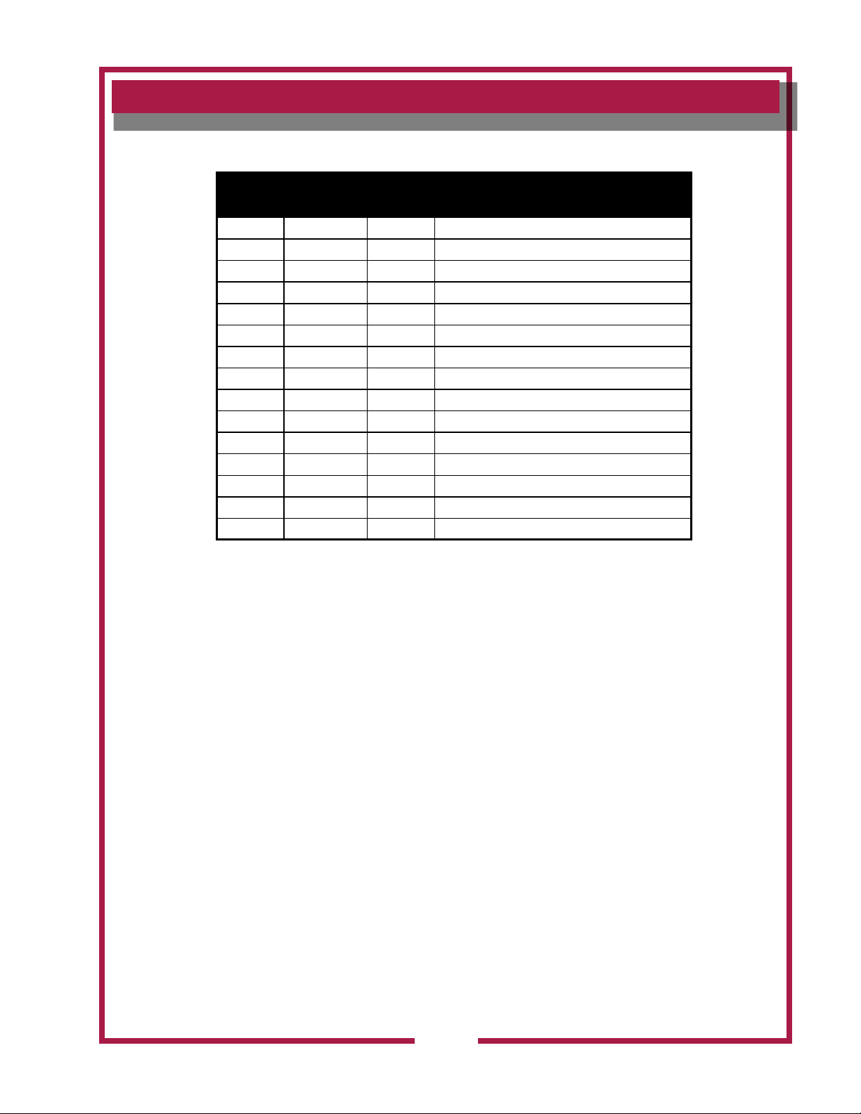
WFAE-55F/FC ELECTRIC OPEN FRYPOT
Fig No Part No Qty Description
1
2 2R-46502 1 MAGNET DOOR
3 E7-46720 1 SUCTION LINE FITTING ASSY
4 2P-47011 2 CASTER RIGID 5”
5 2A-46480 2 LEG 6-7 1/4” ADJUSTABLE
6 2R-38668 1 HANDLE DOOR
7 E7-41713 1 DOOR ASSY WFE WFAE30/WFPE
8 E7-300527 1 GUARD ROD ASSY WFAE55/30
9 E7-46422 1 BRKT HINGE DOOR TOP
10 E7-46423 1 BRKT HINGE DOOR BOTTOM
NI E7-46722 1 PANEL SIDE RT WFAE55/30
NI E7-46723 1 PANEL SIDE LF WFAE55/30
E7-49729
M3-301462 KETTLE ASSY WVAE55
CABINET COMPONENTS
1
KETTLE ASSY WFAE55
363 2M-Z16530 Owners Manual WFAE-55F/FC Free-Standing Electric Fryer
29
Page 32

EXPLODED VIEW: WFAE55F (Manual Controls)
Model: WFAE55F
Free Standing Electric Fryer
Electrical Components (Manual Controls)
PL363
IL1765 Rev. C 10/19/12
CONNECTION BOX
CONTROL PANEL
BEHIND CONTROL PANEL
1
2
22
21
20
19
18
17
16
15
14
13
9
7
7a
11
12
10
8
6
5
4
3
23
WFAE-55F (MANUAL CONTROLS) ELECTRICAL COMPONENTS
363 2M-Z16530 Owners Manual WFAE-55F/FC Free-Standing Electric Fryer
30
Page 33

PARTS LIST: WFAE55F (Manual Controls)
WFAE55F ELECTRIC OPEN FRYPOT
ELECTRICAL COMPONENTS (MANUAL CONTROL)
Fig No Part No Qty Description Application
1 DD-306782 1 RELAY ESAFE-CE 208/240V
2 WS-57779 1 CONTACTOR 3POLE 208V 40A
3
4 WS-66863 1 GASKET KIT ELEM
5 2C-49689 6 CLAMP BULB SS
6 WS-66688 1 THERMO TEMP CTRL
7 WS-66663 1 THERMO HIGH LIMIT Prior to 2009
7a 2T-307574 1 THERMO SAF MAN RESET
8 2R-45653 1 KNOB CONTROL 2.25 OD .25
9 2E-34769 2 FULEHLDR HPG-EE 10A 240V
10 2E-34768 2 FUSE SC-10 10A 300V
11 2E-33068 1 TERM BLOCK 2POLE
12 2E-34005 1 JUMPER FLAME SENSOR TERM
13 2C-41974 2 NUT 8-32 HEX 7/8 LONG ALU
14 WS-50131 1 TERM BLOCK KIT (RETRO)
15 2K-300102 1 STRAIN RELIEF INPT .375-1
16 2P-Z13854 1 TIMER 40MIN 240V SPDT
17 2E-33192 1 PANEL, ON & OFF SWITCH
18 2E-49550 1 SWITCH ROCKER POWER
19 2J-30516 4 LIGHT SIGNAL AMBERR
20 2M-302391 1 FACEPLATE CONTROL WELLS
21 2E-44904 1 SWITCH TOGGLE W/SEAL
22 2J-44834 1 BUZZER 220V ROHS
23 2M-Z13237 1 GRAPHIC LOWER 55F
E7-300009
2N-300013 ELEM ASSY 240V 8.5KW
ELEM ASSY 208V 8.5KW
2
363 2M-Z16530 Owners Manual WFAE-55F/FC Free-Standing Electric Fryer
31
Page 34

EXPLODED VIEW: WFAE55FC (Electronic Control)
Model: WFAE55FC
Free Standing Electric Fryer
Electrical Components (Solid-State Controller)
PL363
IL2584 Rev. A 11/15/12
CONNECTION BOX
CONTROL PANEL
BEHIND CONTROL PANEL
UNIT W/FILTER WAND
FRAME BACKPLATE (EUROPEAN)
1
3
4
6
8
7
3
12
13
10
9
17
18
19
20
21
22
23
24
16
15
14
WFAE-55FC (SOLID-STATE CONTROLLER) ELECTRICAL COMPONENTS
363 2M-Z16530 Owners Manual WFAE-55F/FC Free-Standing Electric Fryer
32
Page 35

PARTS LIST: WFAE55FC (Electronic Control)
WFAE55FC ELECTRIC OPEN FRYPOT
ELECTRICAL COMPONENTS (SOLID STATE CONTROL)
Fig No Part No Qty Description
1 2E-301454 1 TRANSFORMER 208/240V 24V
3 2E-300688 1/3 SPARK QUENCHER, 380-415V ONLY
4
6
7 2J-301465 1 THERMISTOR 91K W/LEADS
8 WS-66863 2 GASKET KIT, ELEMENT
9 2C-49689 6 CLAMP BULB SS F49RT F58RT
10 WS-66663 1 THERMO HI-LIMIT
12 2E-40310 1 TERM BLOCK 4POLE 75AMP
13 2E-44887 1 SWITCH MICRO 120V 15A
14 2E-34005 1 JUMPER FLAME SENSOR TERM
15 WS-53068 1 TERM BLOCK 2POLE
16 2C-41974 2 NUT 8-32 HEX 7/8 LONG ALU
17 WS-50131 1 TERM BLOCK KIT (RETRO)
18 2K-300102 1 STRAIN RELIEF 1NPT .375-1
19 2E-49550 1 SWITCH ROCKER POWER
20 2M-Z16212 1 FACEPLATE CONTROLLER 55FC
21
22 2K-Z1530 4 SPACER
23 2J-Z16356 1 CONTROL CTT
24 2C-2553 4 NUT 6-32 HEX STL NO
WS-57779
WS-57780 CONTACTOR 3POLE 240V 40A
2N-306258UL
E7-300009 ELEM ASSY 208V 8.5KW, 3 PH
2N-306259UL ELEM 240V 5.67KW WFAE, 1 PH
2N-300013 ELEM ASSY 240V 8.5KW WFAE, 3PH
E7-Z16328
CONTACTOR 3POLE 208V 40A
2
ELEM 208V 5.67KW WFAE, 1 PH
2
CONTROL PANEL [RETROFIT KIT WS-WL0334
1
REQUIRED ON MODELS PRODUCED PRIOR
TO 12/04/12]
363 2M-Z16530 Owners Manual WFAE-55F/FC Free-Standing Electric Fryer
33
Page 36

Model: WFAE55F/FC
Free Standing Electric Fryer
Wand & Filter Pump Components
PL363
IL1767 Rev. C 10/19/12
1234
9
14
13
11
11
5
6
7
8
9
10
EXPLODED VIEW: WFAE55F/FC
WFAE-55F/FS FILTER PUMP COMPONENTS
WFAE-55FS WAND COMPONENTS
363 2M-Z16530 Owners Manual WFAE-55F/FC Free-Standing Electric Fryer
34
Page 37
PARTS LIST: WFAE55F/FC
WFAE-55F/FC ELECTRIC OPEN FRYPOT
WAND & FILTER PUMP COMPONENTS
Fig No Part No Qty Description
1 2J-302283 1 HOSE ASSY SS .6 OD X 14
2 2V-46692 1 VALVE CHECK 3/8 NPT WF/WVA
3 WS-501231 1 PUMP ASSY
4 WS-501205 1 MOTOR FILTER 1P 115/230V
5 2I-Z12311 1 GASKET-FIBER WASHER
6 2K-3396X 1 FTG FLEX CONDUIT 90X3/8
7 WS-501205 1 MOTOR FILTER 1P 115/230V
8 2J-302287 1 HOSE ASSY SS 3/4 OD X 16
9 2V-49816 1 VALVE BALL 1-1/4 1500PSIG
10 E7-46720 1 SUCTION LINE FTING ASSY
11 2E-44887 1 SWITCH MICRO 120V 15A
12 DD-304309 1 VALVE 3 WAYS SS
13 DD-304734 1 OIL WAND & HOSE ASSY
14 2V-46692 1 VALVE CHECK 3/8NPT WF/WVA
363 2M-Z16530 Owners Manual WFAE-55F/FC Free-Standing Electric Fryer
35
Page 38

Model: WFAE55F/FC
Free Standing Electric Fryer
AUTO-LIFT COMPONENTS
PL363
IL1769 Rev. C 10/19/12
3
1
2
4
9
5
6
7
8
EXPLODED VIEW: WFAE55F/FC
WFAE-55F/FC AUTO-LIFT COMPONENTS
363 2M-Z16530 Owners Manual WFAE-55F/FC Free-Standing Electric Fryer
36
Page 39

PARTS LIST: WFAE55F/FC
WFAE-55F/FC ELECTRIC OPEN FRYPOT
Fig No Part No Qty Description
1 E7-49961 1 CRADLE LIFT BASKET WFAE55
2 2P-300031 2 BEARING ROLLER .750D X .2
3 2C-41048 2 SCREW 1/4-20-3/4
4 DD-300037 1 PIVOT CRADLE WFAE55
5 2K-49972 1 BUSHING LIFT ROD WFAE55
6 2A-300542 1 ROD LIFT MOTOR WFAE55
7 2V-49812 1 YOKE ROD LIFT MOTOR WFAE55
8 2U-300513 1 MOTOR LIFT 1/10HP 230V 50
9 2C-49843 1 NUT 1-14 FINISH HEX JAM
AUTO-LIFT COMPONENTS
363 2M-Z16530 Owners Manual WFAE-55F/FC Free-Standing Electric Fryer
37
Page 40

EXPLODED VIEW: WFAE55F/FC
Model: WFAE55F/FC
Free Standing Electric Fryer
ACCESSORIES & REMOVABLE COMPONENTS
PL363
IL1768 Rev. B 10/19/12
1
2
3
4
10
5
6
7
8
9
11
12
O-RING FOR
FILTER LEAF
(not shown)
501900
FLAVOR-SAVER
FILTER POWDER
(not shown)
(2M-301698, 9 Pack)
WFAE-55F/FS ACCESSORIES & REMOVABLE COMPONENTS
363 2M-Z16530 Owners Manual WFAE-55F/FC Free-Standing Electric Fryer
38
Page 41

PARTS LIST: WFAE55F/FC
WFAE-55F/FC ELECTRIC OPEN FRYPOT
ACCESSORIES & REMOVABLE COMPONENTS
Fig No Part No Qty Description
1 2B-305097 2 BASKET WIRE TWIN WFAE55
2 2B-301667 1 BASKET FRYER WFA55
3 2B-306245 1 BASKET FRYER WFAE WVAE
4 E7-300235 1 COVER KETTLE WFAE55
5 2B-302203 1 PADDLE STIRRING CHICKEN
6 2P-302204 1 BRUSH CLEANING FRYERS
7 2P-46479 1 BRUSH CLEANING ELEMENT
8 2R-301901 1 SHOVEL STAINLESS STEEL
9 2C-49752 1 DOWEL CLEANOUT DRAIN
10 2I-301847 1 FILTER LEAF
11 2I-46474 5 O-RING .5 ID X .63 OD VIT
12 E7-301845 1 RESERVOIR ASSY WFAE55
NI WS-501900 1 O-RING FILTER LEAF
NI 2M-301698 1 POWDER FILTER 9 PACK WFAE
363 2M-Z16530 Owners Manual WFAE-55F/FC Free-Standing Electric Fryer
39
Page 42

WIRING DIAGRAM
WFAE-55F & FAE-55F
3Ø, 208V OR 240V, 17KW
1L1
1L2
E-SAFE
15
RELAY
1L3
1L1
1
2
3
1L2
1L3
10
"HEAT"
LIGHT
13
9
8
27
POWER
26
SWITCH
C
8A
FUSES (2)
15A MAX
9A
29
30
28
25
19
15
BUZZER
LIGHT
"POWER"
LIGHT
1
2
3
1
2
3
11
BUZZER
28
SAFETY
CONTACTOR
TERMINAL
BLOCK
6
5
4
EXTERNAL INTERLOCK
(REMOVE FOR
EXTERNAL CONTROL)
JUMPER
L3
L2
L1
7
8
9
14
23
33
35
32
34
24
14
BUZZER
SWITCH
COOK
LIGHT
20
17
31
22
TIMER
18
26
GREEN
36
27
OPTIONAL SOLID
SHORTENING MELT
OPTION
24 V PLUMBING
HEATER TAPE
50VA X-FORMER
24V
24 V FILTER PAN
HEATER PAD
FILTER
PUMP
TEMPERATURE
CONTROL
THERMOSTAT
16
WHITE
GREEN
21
25
LIMIT
SWITCHES
INSIDE
MOTOR
HOUSING
BASKET LIFT
ACTUATOR
40
HI LIMIT
THERMOSTAT
BLACK
RED
TERMINATE TIMER MOTOR LEADS
W/ 3/16" INS PO TERM.(2C-38898)
17
18
NOM AMPS PER LINE
VOLTS
208
240
THREE PHASE
L2L1
4848
L3
47
414242
60 HZ
2M-Z13149~
363 2M-Z16530 Owners Manual WFAE-55F/FC Free-Standing Electric Fryer
Page 43

WIRING DIAGRAM
FERRITE CLAMPS ARE USED ON 380V MODEL ONLY
10
11
12
13
18
23
30
17
THERMISTOR
FOR VENTLESS MODELS ONLY
WIRES 40,41,42, AND 43 ONLY NECESSARY ON VENTLESS MODELS
WIRES 36 AND 37 ONLY NECESSARY ON 380V MODELS
37
S
FUSE
15A MAX
2
9A
C
POWER
SWITCH
24
25
42
CONTROLLER
TRANSFORMER
240V
208V
1
28
24V
FILTER
PUMP
16
10
FUSE
15A MAX
27
26
8A
40
30
26
34
363 2M-Z16530 Owners Manual WFAE-55F/FC Free-Standing Electric Fryer
GREEN
27
3
SERVICE
REQUIRED
LIGHT
(RED)
51 51
44
45
REPLACE
FILTER
VACUUM
SWITCH
(SMALL)
45
44
HOOD
REPLACE
FILTER
LIGHT
(AMBER)
46
47
C
NC
55
UPPER CONTROL BOX
8500W ELEMENT
1L1
1L2
1L3
1L1
1L2
1L3
8500W ELEMENT
CONTACTOR
37
9
12
13
24V AC
THERMISTOR
LIFT
COM
TEMP
COM
NO
NO
NC
NC
18
17
S
37
GREEN
NOTE: -WIRE NUMBERS 16, 17 AND 18 ARE ROUTED THRU
A 3/8 INCH FLEXIBLE CONDUIT.
-WIRE NUMBERS 26, 27, AND 36 ARE ROUTED THRU
A 3/8 INCH FLEXIBLE CONDUIT.
11
J4
BASKET LIFT
ACTUATOR
LIMIT SWITCHES
INSIDE MTR HSG
1
2
3
1
2
3
15
14
10
11
WHITE
(COM)
BLACK
(DN)
RED
(UP)
BLOWER
MOTOR
WIRE
NUT(2)
48
49
M
57
42
16
CHECK
FILTER
LIGHT
(AMBER)
53
41
1/4 INS
MALE
INTERVAL TIMER
3
2
1
58
44
37
SAFETY
CONTACTOR
28
14
HI LIMIT
THERMOSTAT
18
17
WFAE55FC
3Ø, 208V,17KW
WVAE55FC
3Ø, 208V,17KW
1Ø, 208V OR 240V, 11.3KW
WFAE55FC
3Ø, 380-415V, 17KW
1/4 INS
MALE(2)
BAFFLE FILTER
MAGNET OPERATED
SWITCH
BUZZER
220V 60HZ
BLACK
BROWN
1/4 INS
1/4 INS
MALE
FEMALE
58
59
59
43
BLD'G ALARM RELAY
(2&4) BEHIND REAR
BOTTOM COVER ON
RIGHT HAND SIDE OF
BOTTOM PANEL.
1
5
NC
4
3
2
NO
COM
41
1/4 INS
FEMALE
56
40
50
54
41
VENTILATOR
POWER
LIGHT
(GREEN)
1/4 INS
FEMALE(2)
HEPA FILTER
MAGNET OPERATED
SWITCH
AIR FLOW
VACUUM
SWITCH
(LARGE)
52
44
RED
M-S
HOOD
56
NO
C
UPPER CONTROL BOX
43
6
5
4
3
2
1
TERMINAL
BLOCK
JUMPER
S
ALTERNATE WIRING FOR 380-415V
23
24
36
S
S
36
3
1
ALTERNATE WIRING FOR SINGLE PHASE OPERATION
1Ø, 208V OR 240V, 11.3KW
* NOT UL LISTED
ON SINGLE PHASE
S
6
5670W ELEMENT
1L1
1L3
1L1
1L3
5670W ELEMENT
VOLTS
208
240
*1Ø, 208
*1Ø, 240
3Ø, 380
SPARK
QUENCHER
(SNUBBER)
380V ONLY
5
4
-----
24 24 24
8
1
3
1
3
FRYER RATING
AMPS
L2L1
4848
56
L1
L2
L3
N
7
L3
L2
L1
7
EXTERNAL INTERLOCK
TERMINAL BLOCK
(REMOVE JUMPER
WHEN EXTERNAL
CONTROL IS USED)
5
4
L3
N
-----
47
-----
414242
-----
-----
-----47-----
-----
5
8
MAIN
TERMINAL
BLOCK
L3
L2
L1
50-60 HZ
2M-Z16338~
JUMPER
41
Page 44

WELLS MANUFACTURING
10 Sunnen Dr., St. Louis, MO 63143
telephone: 314-678-6314
fax: 314-781-2714
www.wellsbloomfield.com
 Loading...