

Page 1
WELLS BLOOMFIELD, LLC
2 ERIK CIRCLE, P. O. Box 280 Verdi, NV 89439
telephone: 775-689-5703
fax: 775-689-5976
www.wellsbloomfield.com
SUPPLEMENTAL
SERVICE
INSTRUCTIONS
ELECTRIC
363
for
FRYER
WFAE-55F
WFAE-55FS
With or Without
Optional Filter Wand
IMPORTANT: WELLS MANUFACTURING PROPRIETARY INFORMATION.
DISSEMINATION OF THIS INFORMATION TO ANYONE OTHER THAN
WELLS AUTHORIZED SERVICE AGENTS IS STRICTLY PROHIBITED.
TECHNICAL CONTENT OF THIS MANUAL IS DESIGNED FOR
USE BY QUALIFIED PROFESSIONAL TECHNICIANS ONLY.
PRINTED IN UNITED STATES OF AMERICA
p/n 507398 Rev. A ECN-13391 S363 071128 cps
Page 2
PRECAUTIONS AND GENERAL INFORMATION
DANGER:
BURN HAZARD
Cooking oil in this appliance
operates at very high
temperatures. Contact with
hot oil can cause severe
injury or death. Wear
appropriate heat-protective
clothing when operating or
servicing this appliance.
WARNING:
SLIP AND FALL
HAZARD
Spilled cooking oil is very
slippery and can cause falls.
Clean up oil spills promptly.
CAUTION:
BURN HAZARD
Exposed surfaces can be hot
to the touch and may cause
burns.
CAUTION:
HEALTH HAZARD
Old cooking oil can be a
breeding ground for bacteria.
Clean and sanitize exterior
surfaces of fryer regularly.
This appliance is intended for use in commercial establishments
only.
This appliance is intended
No other use is
agents.
DO NOT open any panel that requires the use of tools for access. Live
electric circuits may be exposed by opening such panels. Opening
access panels must be performed by an Authorized Service Agent
only.
This appliance is equipped with an oil filtration system designed to filter
hot liquid shortening only. Water, cleaning agents and/or other liquids
will contaminate the oil and may damage the filter pump.
Operators of this appliance must be familiar with the appliance use,
limitations and associated restrictions. Operating instructions must be
read and understood by all persons using or installing this appliance.
Cleanliness of this appliance is essential to good sanitation. Read and
follow all included cleaning instructions and schedules to ensure the
safety of the food product.
DO NOT submerge any part of this appliance in water unless
specifically instructed to do so. This appliance is not jet stream
approved. DO NOT direct water jet or steam jet at this appliance,
nor at any control. DO NOT splash or pour water on, in or over any
controls. DO NOT wash area around this appliance with water jet.
Any part which has become wet must be thoroughly dried before use.
Cooking oil will be very hot when in use. Contact will cause severe
injury, and can cause blindness or death. Wear appropriate heatprotective clothing when operating or servicing this appliance.
This appliance must be operated with the supplied legs and casters
properly installed.
The technical content of this manual, including any parts breakdown
illustrations and/or adjustment procedures, is intended for use by
qualified technical personnel only.
Any procedure which requires the use of tools must be performed by a
qualified technician.
recommended or authorized by the manufacturer or its
to prepare food for human consumption.
363 503043 Service Manual for WFAE-55F/FS Fryer
xi
Page 3
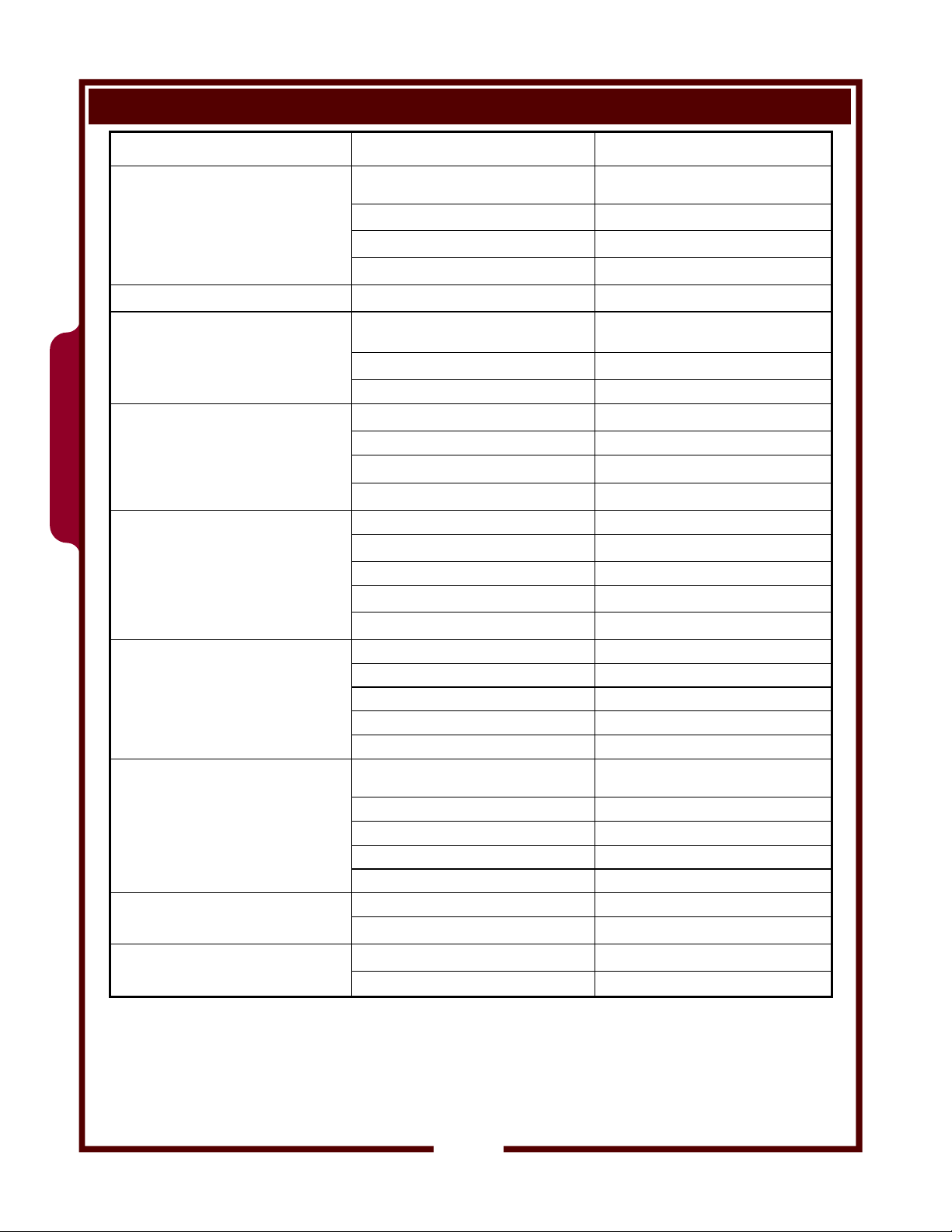
TABLE OF CONTENTS
Precautions & General Information xi
Specifications 1
WFAE-55F Manual Controls
Components and Controls 2
Operation 4
Operation Troubleshooting Guide 5
WFAE-55FS Solid State Controls
Components and Controls 6
Operation 8
Programming - Custom Settings for Customer Needs 9
Operation Troubleshooting Guide & Error Codes 10
Filter Operation 12
Filter System Troubleshooting Guide 13
Servicing Instructions
Lift Actuator & Motor Assembly 14
Filter Pump 16
Electrical Components 18
Heating Element & Thermostat 22
Wiring Diagrams 24
INTRODUCTION
This manual contains information needed to properly service and repair WFPE-30FS Pressure Fryer.
For installation, operation and maintenance instructions, refer to the Operation Manual p/n 300 007.
SPECIFICATIONS
363 503043 Service Manual for WFAE-55F/FS Fryer
DIMENSIONS
CAPACITIES
VOLTAGE
REQUIREMENTS
POWER
CONSUMPTION
AMPERAGE
(Liquid Shortening Only)
Wide Deep High
15.70” 37.38” 48.94” (Basket Up)
Cooking Oil
Lbs. Kg.
55
Chicken (Fresh) 30 13
Chicken (Frozen) 25 11
ELECTRICAL SPECIFICATIONS
DOMESTIC EXPORT (EU)
208 VAC
17,000 watts
47.8 amps (3ø)
43.0 amps (3ø)
240VAC
17,000 watts
380-415V
3NAC
17,000 watts
L1 = 27.0
L2 = 27.0
L3 = 27.0
N = 3.0
25
1
Page 4
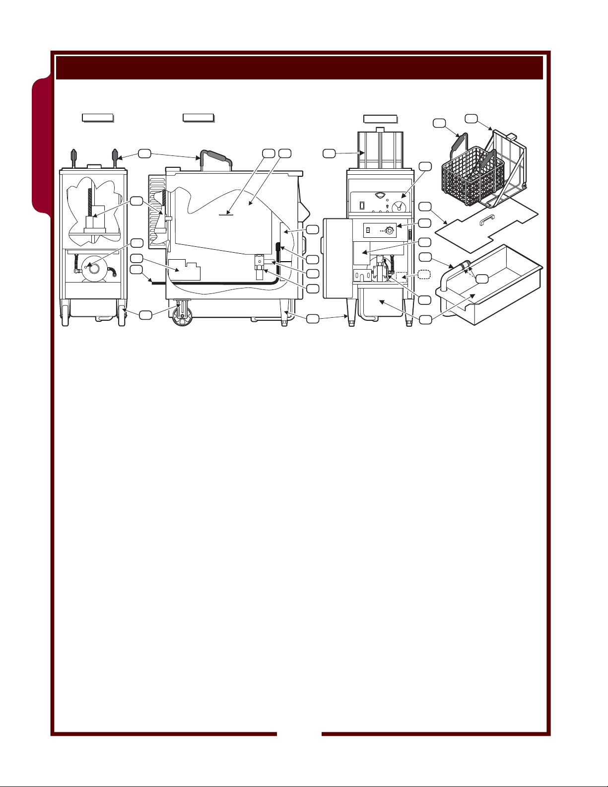
COMPONENTS & MANUAL CONTROLS
WFAE-55F
WFAE-55F
BACK VIEW SIDE VIEW
M
FRONT VIEW
T
E
D
M
N
D
A
COLDOIL LEVEL
J
B
G
H
I
K
Q
F
L
C
O
J
U
P
Q
R
V
ITEM DESCRIPTION NOTES
A LIFT CRADLE MOTOR Operates LIFT ROD / Raises LIFT CRADLE
B PUMP MOTOR RESET Protects against filter pump motor overload
NOTE: must be reset by manually pushing red button
C FRYPOT COVER Protects against hot oil splatter during use, helps prevent oil contamination
D LIFT CRADLE Holds FRY BASKET - lifts/lowers fry basket into/out of frypot
E FRYPOT ASSEMBLY Contains and heats cooking oil
F DRAIN VALVE Allows draining FRYPOT
G FILTER PUMP and MOTOR Pumps oil during filtration cycle
H POWER CORD Electrical power hook-up
I REAR (FIXED) CASTER Allow easy positioning of unit
J LOWER CONTROL BOX
and TERMINAL BOX COVER
Contains power cord connections, power contactor, temperature control
thermostat, hi-limit safety thermostat and heating element connections
K POWER CONNECTION 90º conduit fitting required, angled as shown
L FRONT (FIXED) LEG Adjustable for leveling unit
M FRY BASKEY Holds product to be cooked
N UPPER CONTROL PANEL Contains main controls. See page 3
O LOWER CONTROL PANEL Contains heating controls and pump switch. See page 3
P DRIP PAN Collects liquids that drain from the top of the unit
Q DRAIN VALVE LEVER Operates the drain valve (item F)
R FILTER RESERVOIR Holds filtering media for oil filtration cycle
T OIL LEVEL INDICATOR Measure amount of cooking oil
U FILTER SUCTION TUBE Plugs into suction line receptacle
Allows oil to be drawn through filter media
V SUCTION TUBE O-RING
SPARE O-RINGS
Seals suction tube to receptacle
Up to 3 spares may be stored here
363 503043 Service Manual for WFAE-55F/FS Fryer
2
Page 5
WFAE-55F
COMPONENTS & MANUAL CONTROLS (continued)
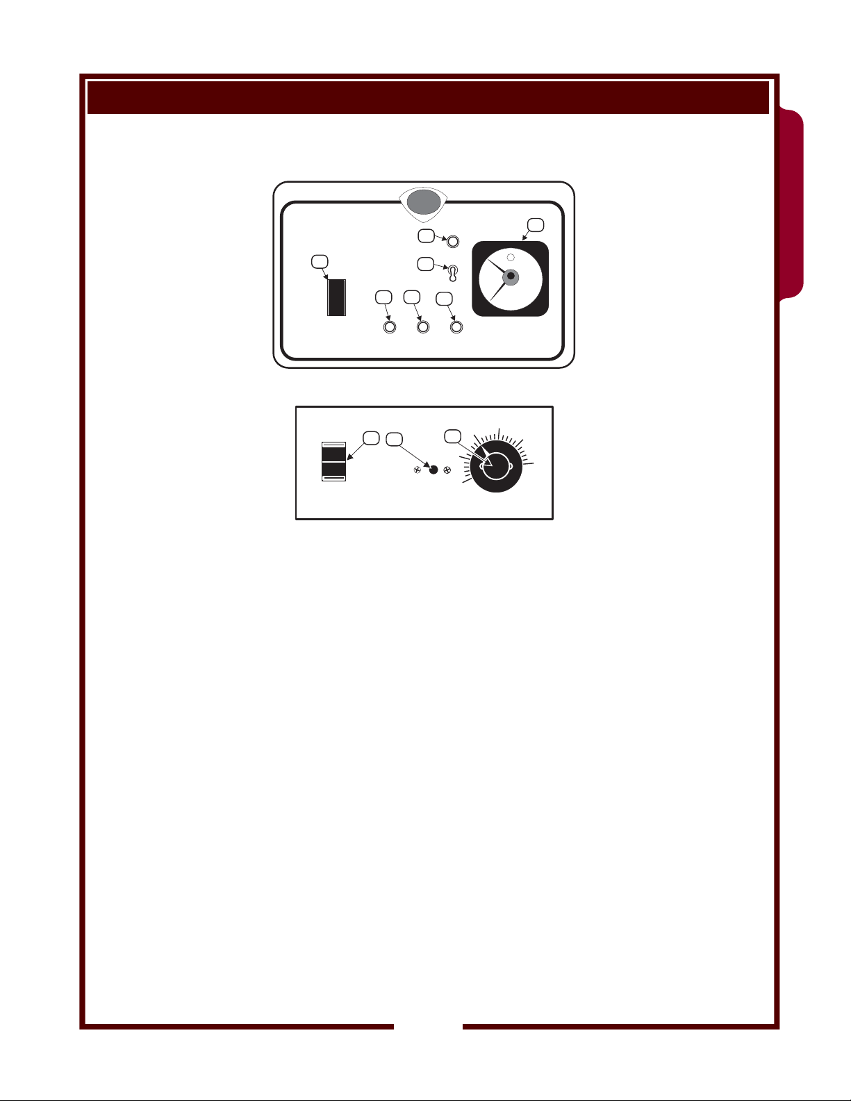
UPPER CONTROL PANEL
WELLS
7
1
FRYER
OFF
FILTER
2
POWER
LOWER CONTROL PANEL
FILTER
ON
8
OFF
CAUTION
FRYER MUST BE OFF
BEFORE USING FILTER
6
3
HEAT
9
HI-LIMIT
RESET
B
U
Z
Z
E
R
4
COOK
THERMOSTAT
300
10
250
275
5
WFAE-55F
325
350
375
ºF
ITEM DESCRIPTION NOTES
1 POWER SWITCH FRYER position energizes temperature control thermostat and timer
2 POWER LIGHT Glows when power switch is in FRYER position
3 HEAT LIGHT Glows when heating element is energized
4 COOK LIGHT Glows when cook lever is in COOK position
5 TIMER Indicated set time or counts down time remaining
6 BUZZER SWITCH ON position allows buzzer to sound whenever cradle is down
7 BUZZER LIGHT Glows when BUZZER SWITCH is ON
8 FILTER SWITCH ON position energizes filter pump (power switch must be in FILTER position)
9 HI-LIMIT SAFETY
THERMOSTAT
10 TEMPERATURE CONTROL
THERMOSTAT
363 503043 Service Manual for WFAE-55F/FS Fryer
FILTER position energizes filter switch
OFF position de-energizes temperature control thermostat, timer and filter
switch
Active when cook lever is in COOK position
OFF position silences buzzer
Turns fryer OFF is cooking oil temperature exceeds 425ºF
Turns fryer OFF if heating element is energized without being covered by
cooking oil
RESET by pressing red button after cooking oil has cooled.
Controls cooking oil temperature by energizing/de-energizing heating element
SET by turning pointer to desired cooking temperature marked on panel
Causes heat light to glow when energized
3
Page 6
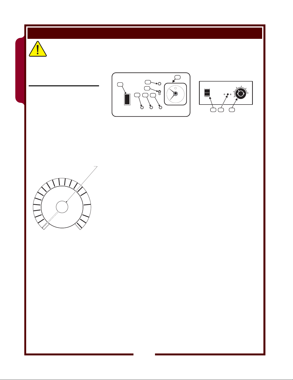
OPERATION - MANUAL CONTROLS
CAUTION:
WFAE-55F
BURN HAZARD
Hot oil can cause serious burns
on contact. Wear appropriate
protective clothing when using
this fryer.
TURN TO SET TIME
PRESS RED BUTTON TO START TIMER
11
10
9
8
7
6
5
4
3
2
1
0
TIMER
12
13
21
14
20
15
19
16
17
18
PRE-HEATING FRYER
Make sure FRYPOT is filled with 55 LB. of cooking oil.
Open door and set THERMOSTAT (item 10) to desired cooking
temperature. CLOSE THE DOOR.
5
1
FRYER
OFF
FILTER
UPPER CONTROL PANEL
7
6
2
3
POWER
B
U
Z
Z
E
R
4
COOK
HEAT
LOWER CONTROL PANEL
FILTER
ON
OFF
CAUTION
FRYERMUST BE OFF
BEFOREUSING FILTER
HI-LIMIT
RESET
8
9
THERMOSTAT
300
275
250
10
325
350
375
ºF
Set POWER SWITCH (item 1) to FRYER. POWER LIGHT (item 2)
and HEAT LIGHT (item 3) will glow. HEAT LIGHT will cycle on and
off with the HEATING ELEMENTS. When HEAT LIGHT first goes off,
fryer is ready to cook the product.
SET COOK TIMER AND LOAD PRODUCT
Set TIMER (item 5) to desired cooking time.
FROZEN PRODUCT:
Load frozen product into BASKET. Set BASKET on LIFT
CRADLE.
Press RED BUTTON on TIMER to lower BASKET into FRYPOT.
FRESH PRODUCT:
Set BASKET on LIFT CRADLE.
Press RED BUTTON on TIMER to lower BASKET into FRYPOT.
Manually drop each piece of fresh product into hot oil, just above
the oil level to minimize splattering.
ALWAYS USE PROTECTIVE EQUIPMENT, SUCH AS INSULATED
GLOVES, TO PROTECT AGAINST HOT OIL BURNS
COOK CYCLE AND BUZZER
When an audible alarm is desired at end of cook cycle, turn BUZZER
SWITCH (item 7) ON after TIMER has been started. BUZZER LIGHT
(item 6) will glow.
Note: If BUZZER SWITCH is turned ON before BASKET is lowered,
BUZZER will sound until BASKET has fully lowered.
At end of cook cycle, BASKET will raise. BUZZER will sound until
BUZZER SWITCH is turned OFF, or until the next cook cycle is
started.
Use plastic-coated handles on fry basket to remove basket of cooked
product from LIFT CRADLE. Serve or dispense cooked product as
required.
363 503043 Service Manual for WFAE-55F/FS Fryer
4
Page 7
OPERATION (MANUAL CONTROLS) TROUBLESHOOTING GUIDE
SYMPTOM POSSIBLE CAUSE SUGGESTED REMEDY
POWER LIGHT not lit
Fryer not operating
POWER LIGHT not lit POWER LIGHT damaged Repair or replace power light
POWER SWITCH not in FRYER position Press POWER SWITCH to FRYER
Disconnected from electric power or Reconnect to electric power
TEMPERATURE CONTROL THERMOSTAT not
HEAT LIGHT not lit
Power light lit - cooking oil cold
HEAT LIGHT not lit HI-LIMIT SAFETY THERMOSTAT tripped Allow oil to cool, press red button to reset hi-limit
HEAT LIGHT not lit
Power light lit - cooking oil hot
COOK LIGHT not lit (CRADLE raised) TIMER not set or not started Turn dial to desired time, press red start button
COOK LIGHT not lit (CRADLE lowered) COOK LIGHT damaged Repair or replace cook light
TIMER does not operate
BUZZER LIGHT not lit
BUZZER does not sound (CRADLE raised)
CRADLE LIFT will not lower
set or set too low
TEMPERATURE CONTROL THERMOSTAT Replace thermostat
Cooking oil at set temperature No action required
HEAT LIGHT damaged Repair or replace heat light
POWER SWITCH not in FRYER position Press POWER SWITCH to FRYER
TIMER not set or not started
TIMER CAM MICROSWITCH damaged or out of
adjustment
TIMER damaged Replace TIMER
BUZZER SWITCH in OFF position Turn SWITCH ON
BUZZER LIGHT damaged Replace LIGHT
BUZZER SWITCH in OFF position Turn SWITCH ON
BUZZER damaged Replace BUZZER
BUZZER SWITCH damaged Replace BUZZER SWITCH
TIMER not set or not started Turn dial to desired time, press red start button
TIMER damaged Replace TIMER
LIFT MOTOR damaged Replace LIFT MOTOR
Set thermostat to desired temperature
Turn dial to desired time, press red button to
start
Adjust or replace microswitch
WFAE-55F
CRADLE LIFT will not raise
FRYPOT COVER does not lower with LIFT
363 503043 Service Manual for WFAE-55F/FS Fryer
CRADLE
LIFT MOTOR MICROSWITCH damaged or out of Adjust or replace microswitch
TIMER has time remaining Allow TIMER to complete cycle to “0”
LIFT CRADLE not properly assembled to LIFT
ROD
TIMER damaged Replace TIMER
LIFT MOTOR damaged Replace LIFT MOTOR
LIFT MOTOR MICROSWITCH damaged or out of
adjustment
ACTUATOR or LIFT CRADLE damaged Repair/replace damaged components
COVER leaned back too far Rest COVER on LIFT CRADLE
HINGE(S) dirty, damaged or misaligned Clean, repair or align HINGES
Install white plastic pivot over end of LIFT ROD
(see page 3)
Adjust or replace microswitch
5
Page 8

COMPONENTS & SOLID STATE CONTROLS
WFAE-55FS
BACK VIEW SIDE VIEW
T
M
E
FRONT VIEW
D
M
N
D
WFAE-55FS
ITEM DESCRIPTION NOTES
A LIFT CRADLE MOTOR Operates LIFT ROD / Raises LIFT CRADLE
B PUMP MOTOR RESET Protects against filter pump motor overload
C FRYPOT COVER Protects against hot oil splatter during use, helps prevent oil contamination
D LIFT CRADLE Holds FRY BASKET - lifts/lowers fry basket into/out of frypot
E FRYPOT ASSEMBLY Contains and heats cooking oil
F DRAIN VALVE Allows draining FRYPOT
G FILTER PUMP and MOTOR Pumps oil during filtration cycle
H POWER CORD Electrical power hook-up
I REAR (FIXED) CASTER Allow easy positioning of unit
J LOWER CONTROL BOX
K POWER CONNECTION 90º conduit fitting required, angled as shown
L FRONT (FIXED) LEG Adjustable for leveling unit
M FRY BASKEY Holds product to be cooked
N UPPER CONTROL PANEL Contains main controls. See page 3
O LOWER CONTROL PANEL Contains heating controls and pump switch. See page 3
P DRIP PAN Collects liquids that drain from top of fryer (when used in a ventless unit)
Q DRAIN VALVE LEVER Operates the drain valve (item F)
R FILTER RESERVOIR Holds filtering media for oil filtration cycle
T OIL LEVEL INDICATOR Measure amount of cooking oil
S SOLID SHORTENING MELT OPTION Heated components to prevent pump damage when using solid shortening
U FILTER SUCTION TUBE Plugs into suction line receptacle
V SUCTION TUBE O-RING
A
B
G
H
S
I
and TERMINAL BOX COVER
SPARE O-RINGS
COLDOIL LEVEL
C
J
K
Q
F
L
S
O
J
U
P
Q
R
V
NOTE: must be reset by manually pushing red button
Contains power cord connections, power contactor, temperature control
thermostat, hi-limit safety thermostat and heating element connections
(NOTE: must be ordered as a specific option at time of build)
Allows oil to be drawn through filter media
Seals suction tube to receptacle
Up to 3 spares may be stored here
363 503043 Service Manual for WFAE-55F/FS Fryer
6
Page 9
WFAE-55FS
COMPONENTS & SOLID STATE CONTROLS (continued)
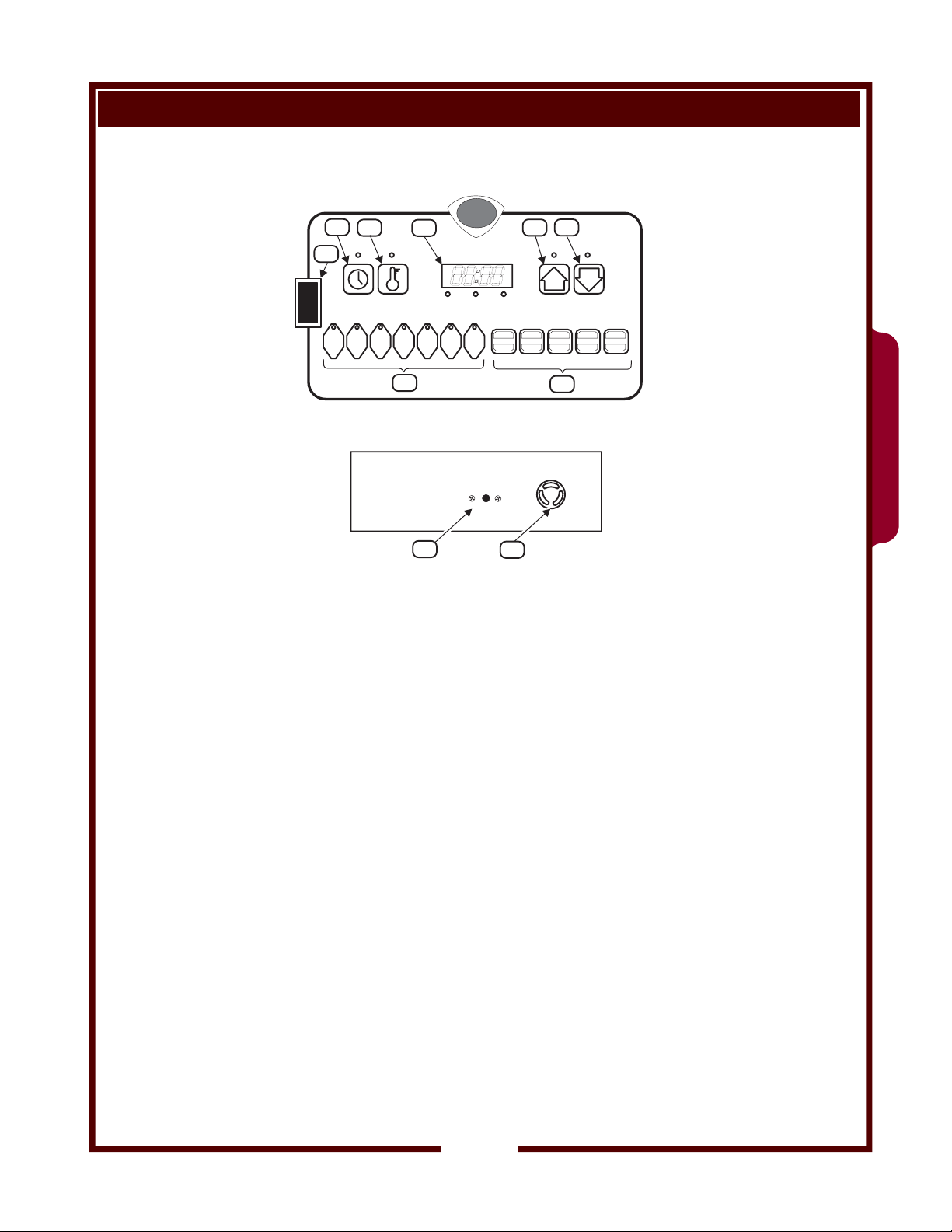
UPPER CONTROL PANEL
2
3
WELLS
4
6
5
1
FRYER
FILTER
TIME TEMP
OFF
1234
7
HEAT READY MANUAL
MANUAL
56
PAUSE CLEAN STANDBY BASKET FILTER
7
8
LOWER CONTROL PANEL
HI-LIMIT
RESET
9
10
ITEM DESCRIPTION NOTES
1 POWER SWITCH
(FRYER - OFF - FILTER)
FRYER position energized fryer and de-energizes filter pump
OFF position de-energizes fryer and filter pump
FILTER position allows filter pump operation and de-energizes fryer
2 TIME KEY Used to check and set menu times
3 TEMP KEY Used to check and set menu temperatures
4 READOUT LED display of various functions and data
5 UP ARROW KEY Used to raise fry basket, and to change program settings
6 DOWN ARROW KEY Used to lower fry basket, and to change program settings
7 MENU KEYS Used to start a menu time/temp cycle
Keys 1 - 6 are programmable for time and temperature
Key 7 available for individually set time/temp cook cycles
8 FUNCTION KEYS Used to perform functions of PAUSE, CLEAN, STANDBY, raise/lower BASKET
acknowledge FILTER warning
9 HI-LIMIT THERMOSTAT Turns fryer OFF is cooking oil temperature exceeds 425ºF
Turns fryer OFF if heating element is energized without being covered by
cooking oil
RESET by pressing red button after cooking oil has cooled.
10 SONALERT Audible alert to signal end of cook cycle and other programmed functions
WFAE-55FS
363 503043 Service Manual for WFAE-55F/FS Fryer
7
Page 10

OPERATION - SOLID STATE CONTROLS
Hot oil can cause serious burns
on contact. Wear appropriate
protective clothing when using
this fryer.
Controller operation for solid
shortening melt optioned fryers
is essentially identical to the
WFAE-55FS
operation of the standard solid
state controller. Important
differenced are noted in the
text.
CAUTION:
BURN HAZARD
1
2
3
5
4
12
MANUAL
7
BASKET
MANUAL
6
7
MANUAL
PROGRAMMING KEY FUNCTIONS
2
3
4
6
5
1
FRYER
OFF
FILTER
TIME TEMP
1234
7
As each control panel key is pressed, a “beep” will sound. Illuminated
indicator light for each key will light whenever that key is pressed, and
any time the function associated with that key is active.
FRYER - OFF - FILTER switch (item 1) allows the fryer to be placed
in a normal cook mode (FRYER), an oil-filtering mode (FILTER) or
turned OFF.
TIME key (item 2) controls time functions.
TEMP key (item 3) controls temperature functions. Data can be read
on the solid state READOUT (item 4).
HEAT indicator is lit whenever the burners are energized; READY
indicator is lit when cooking oil is at programmed temperature.
MANUAL indicator is lit whenever MENU key 7 is selected.
Arrow keys (item 5 & 6) control the basket lift (after pressing BASKET
key), and are used to scroll through program settings.
MENU keys (item 7) allow a choice of six (or seven) pre-programmed
time / temp settings.
Suggestion: MENU keys 1 and 2 incorporate a feature that will
inform the operator when to “drop” wings and drumsticks during cook
cycle. “Drop” feature will allow you to cook breasts and thighs longer
than wings and drumsticks by sounding a beep, and displaying “
on readout (item 4). Your fryer installer can program this feature
into your controller upon request.
Any selected MENU key can be cancelled by pressing and holding
for 3 seconds.
MENU key 7 is unprogrammed so that special or one-of-a-kind
product may be programmed any time:
With fryer is ON, press and hold TIME key and MENU 7 key
at the same time.
Press the UP or DOWN arrow key until the desired time is
displayed.
If this MANUAL feature is not desired, MENU key 7 may be
programmed in the identical fashion to MENU keys 1 thru 6.
HEAT READY MANUAL
56
MANUAL
7
PAUSE
8a
CLEAN STANDBY
8b
8c
BASKET
8d
FILTER
8e
DrOP
363 503043 Service Manual for WFAE-55F/FS Fryer
”
8
Page 11

PROGRAMMING - SOLID STATE CONTROLS
SERVICE MODE PROGRAMMING
CUSTOMIZING PROGRAMMING FOR END USER SPECIAL NEEDS
PRESS DISPLAY DESCRIPTION and DEFAULT RANGE
POWER SWITCH ON 00:00 Energize fryer none
Aut alternates with 0
Pb 1 alternates with 0
StP
Loop
nnS
CLE
alternates with 275º(F)
alternates with 135º(C)
CLE
bStP
Oil alternates with 5
Per alternates with 19
AUdF
AUdd
AUdn alternates with 10
00:00 Return to operating mode none
Enter Service Mode Programming
AUTO-TUNE
PROPORTIONAL BAND
Factory set at 0
alternates with
or 2 or 3
1
COOKING PROGRAM STEPS
Factory set at 1
alternates with OFF SHORTED SENSOR PROTECTION
Factory set at OFF
SOLID SHORTENING MELT CYCLE
alternates with OFF
Factory set at OFF for units without melt option
Factory set at ON for units with melt option
or
alternates with
CleanTemp
COOL DOWN TEMPERATURE
Factory set to 275ºF or 135ºC
CLEANING SET POINT TEMPERATURE
Factory set to 200ºF or 93ºC
Set on installation for site altitude
OIL FILTER MENU CYCLES COUNTER
Factory set to 5
DROP CYCLE ALARM
Factory set 19 % of elapsed time (menu 1, 2)
alternates with –2
alternates with –1
FILTER CYCLE ALARM Configuration
Factory set to 2 sec. ON / 2 sec. OFF
DROP ALARM Configuration
Factory set to 1 sec. ON / 1 sec. OFF
END OF MENU Configuration
Factory set to 1 tone, 10 sec. long
DO NOT CHANGE
0
0
DO NOT CHANGE
1, 2 or 3
ON or OFF
Leave OFF
ON or OFF
Leave OFF for all units not
equipped with melt option
195ºF to 350ºF
93ºC to 191ºC
185ºF to 208ºF
85ºC to 99ºC
see BOIL CHART below
0 = OFF
1 to 20 = # of loads for alert
0 = OFF
1 (%) to 90 (%)
-10 to -1 = seconds ON/OFF
1 to 59 = seconds on
0 = OFF, 60 = continuous
-10 to -1 = seconds ON/OFF
1 to 59 = seconds on
0 = OFF, 60 = continuous
-10 to -1 = seconds ON/OFF
1 to 59 = seconds on
0 = OFF, 60 = continuous
WFAE-55FS
Once in the Service Mode (Aut
210
205
363 503043 Service Manual for WFAE-55F/FS Fryer
200
195
TEMP. (ºF)
190
0
500
1,000
ELEVATION (feet above sea level)
NOTE: If no key is pressed within 30 seconds, controller will revert to operating mode.
displayed), TIME key must be pressed 12 times to complete programming cycle and save changes.
Alternately, wait 30 seconds for controller to revert to operating mode without saving changes.
BOILING POINT OF WATER and CLEANING TEMPERATURE SETTING - - - BASED ON ALTITUDE
100
97
94
91
TEMP. (ºC)
88
1,500
2,000
2,500
3,000
3,500
4,000
4,500
5,000
5,500
6,000
6,500
0
300
150
450
600
750
900
1.050
1.200
1.350
ELEVATION (meters above sea level)
BOILING POINT OF WATER
9
MAXIMUM TEMPERATURE SETTING
1.500
1.650
1.800
1.950
Page 12
TROUBLESHOOTING GUIDE (SOLID STATE CONTROLS)
SYMPTOM POSSIBLE CAUSE SUGGESTED REMEDY
READOUT not lit
(Fryer not operating)
(Fryer operating norm.) CONTROLLER damaged Replace CONTROLLER
HEAT LIGHT not lit
(READOUT lit /cooking oil cold)
WFAE-55FS
COOKING OIL COLD
(HEAT light lit)
CRADLE LIFT won’t lower Improper key strokes Press ”BASKET” then “DOWN ARROW”
POWER SWITCH not
in FRYER position
Circuit breaker OFF or tripped Reset circuit breaker
Service wiring problem Correct service wiring
Controller connection faulty Check/replace connector
Programmed temperature too low Raise programmed temperature
HI-LIMIT THERMOSTAT tripped Allow oil to cool, reset HI-LIMIT
CONTROLLER damaged Replace CONTROLLER
HEATING ELEMENT damaged Replace HEATING ELEMENT
Wiring problem / loose connection Correct wiring problem
TEMP PROBE damaged Replace PROBE
CONTROLLER damaged Replace CONTROLLER
LIFT MOTOR damaged Replace LIFT MOTOR
DOWN RELAY damaged Replace RELAY
Wiring problem / loose connection Correct wiring problem
CONTROLLER damaged Replace CONTROLLER
Press POWER SWITCH
to FRYER position
select another MENU KEY
CRADLE LIFT won’traise READOUT not “00:00” or “PAUSE” Press “PAUSE” + “UP ARROW”
LIFT MOTOR damaged Replace LIFT MOTOR
UP RELAY damaged Replace RELAY
Wiring problem / loose connection Correct wiring problem
CONTROLLER damaged Replace CONTROLLER
BUZZER does not sound, or is not
loud enough
MENU KEY does not operate MENU KEY not programmed Program MENU KEY. See pg. 8
FUNCTION KEY does not operate
Buzzer programmed OFF See page 9
BUZZER SHUTTER closed Open SHUTTER
BUZZER damaged Replace BUZZER
Wiring problem / loose connection Correct wiring problem
CONTROLLER damaged Replace CONTROLLER
CONTROLLER damaged Replace CONTROLLER
Improper KEY entry See pg. 8 for proper usage
CONTROLLER damaged Replace CONTROLLER
363 503043 Service Manual for WFAE-55F/FS Fryer
10
Page 13
ERROR CODES (SOLID STATE CONTROLS)
ERROR CODE / PROBLEM POSSIBLE CAUSE SUGGESTED REMEDY
Er01
Read Only Memory checksum error
Er02
Random Access Memory checksum error
Er03
Ambient temperature sensor error
Er04
Configuration error
Er05
EEprom error
Er06*
Zone 1 Analog/Digital underflow error
Er07*
Zone 1 Analog/Digital overflow error
Er08*
Zone 2 Analog/Digital underflow error
Internal ROM corrupted Press power switch to OFF, then ON
Internal RAM corrupted Press power switch to OFF, then ON
Ambient temperature is below 32ºF/0ºC Verify ambient temperature agrees with
temp readout
Factory calibration parameters altered Restore factory calibration (call factory
for calibration instructions)
Microprocessor functions halted Press power switch to OFF, then ON
Replace controller
Stored data corrupted or incomplete Press power switch to OFF, then ON
Reprogram controller
Sensor leads reversed Verify sensor connection polarity
Incorrect sensor type Contact factory for instructions for
verifying InP1 parameter.
Verify InP1 matches sensor
Measured temp outside sensor range Verify temp within sensor range
Open sensor Verify sensor connections
Replace sensor
Sensor leads reversed Verify sensor connection polarity
Incorrect sensor type Contact factory for instructions for
verifying InP1 parameter.
Verify InP1 matches sensor
Measured temp outside sensor range Verify temp within sensor range
WFAE-55FS
Er09*
Zone 2 Analog/Digital overflow error
Er10
Stack overflow error
Er11*
Zone 1 open sensor error
Er12*
Zone 1 shorted sensor
Er13*
Zone 2 open sensor error
Er14*
Zone 2 shorted sensor
Er15*
Zone 1 loop error
Er16*
Zone 2 loop error
363 503043 Service Manual for WFAE-55F/FS Fryer
* These errors will automatically clear when the condition causing the alarm has been resolved.
In all instances of error message, check connections of probes to controller for tightness and polarity.
Open sensor Verify sensor connections
Microprocessor error Press power switch to OFF, then ON
Open sensor Verify sensor connections
Incorrect sensor type
Measurement outside of sensor range
Open sensor Verify sensor connections
Incorrect sensor type
Measurement outside of sensor range
Shorted sensor Check connections / replace sensor
Incorrect Pb1/Pb2 value See programming instructions, page 9
Damaged heating element / wiring Replace element / repair wiring
Damaged heating relay / wiring Replace relay / repair wiring
Replace sensor
Replace sensor
Verify correct sensor
Verify sensor connections
Replace sensor
Replace sensor
Verify correct sensor
Verify sensor connections
Replace sensor
11
Page 14

FILTER LEAF ASSEMBLY
MAINTENANCE INSTRUCTIONS - FILTER OPERATION
WARNING
WARNING: BURN HAZARD
HOT OIL SPILL OR SPLATTER
DO NOT REMOVE FILTER RESERVOIR WHEN IT CONTAINS HOT OIL
HOT OIL WILL CAUSE SEVERE BURNS ON CONTACT
PROTECTIVE CLOTHING AND GLOVES MUST BE WORN
DURING THE FILTERING PROCESS
Death or serious injury may result from contact with, or slipping and falling in, spilled oil.
WARNING
WARNING:
BURN HAZARD
DO NOT REMOVE FILTER RESERVOIR IF IT IS HOT.
WEAR INSULATED GLOVES OR ALLOW IT TO COOL.
Hot oil quickly heats reservoir. Touching hot reservoir
with bare hands can causing serious injury
Clean FILTER LEAF after each day’s filtration, or as needed to return
oil promptly to the kettle.
Open FRYER DOOR and slide the FILTER RESERVOIR forward to
remove it. Remove FILTER LEAF from reservoir.
Disassemble FILTER LEAF by separating the two side rails at the
joint with the straight pin. Clean all components in a sink with warm
water and mild detergent, or in a dishwasher.
Assemble SCREEN with the SEPARATOR installed between the
two screens. Verify that O-RING is in place on the suction tube on
BOTTOM SCREEN.
Slide screens into SIDE RAIL “B” (L-shaped pin). Hook SIDE RAIL
“A” over the pin on SIDERAIL “B” and work the screens into SIDE
RAIL “A” until straight pin on “A” is held by the “bump” on “B”.
STRAIGHT
PIN
FILTER RAIL “A”
UPPER
FILTER SCREEN
SEPARATOR
FILTER SCREEN
“L”-SHAPED
PIN
FILTER RAIL “B”
LOWER
TOP VIEW
Install FILTER LEAF in RESERVOIR with suction tube firmly into
filter drain hole.
Install filter reservoir into the fryer. Make sure the “O” ring closest
to end of SUCTION TUBE is firmly seated in SUCTION LINE
RECEPTACLE.
SIDE VIEW
IMPORTANT: Make sure all oil
is pumped into FRYPOT before
removing reservoir.
NOTE:
When properly assembled,
handle will point away from
suction tube on BOTTOM
SCREEN.
NOTE:
Inspect the “O” RING on
FILTER SUCTION TUBE for
damage. Replace “O” ring if it
is cut, cracked or scuffed using
one of the spare o- rings in the
suction tube groove.
IMPORTANT:
Avoid contaminating the oil or
food product by verifying that all
components of filter reservoir
assembly are completely dry
before reassembling.
363 503043 Service Manual for WFAE-55F/FS Fryer
12
Page 15

FILTER SYSTEM
SYMPTOM POSSIBLE CAUSE SUGGESTED REMEDY
FILTER PUMP does not run
FILTER SYSTEM TROUBLESHOOTING
POWER SWITCH not in FILTER Press power switch to filter
FILTER PUMP MOTOR OVERLOAD
tripped
FILTER SWITCH damaged Replace filter switch
POWER SWITCH damaged Replace power switch
SUCTION TUBE not seated in suction
receptacle
SUCTION TUBE O-RING missing or
damaged
Allow motor to cool. Press red button on
back of pump motor
Properly install filter reservoir
Replace suction tube o-ring
FILTER PUMP runs but will not pump
cooking oil
Bubbles in circulating oil at all times during
filtration cycle
PUMP MOTOR tripped
Will not reset
Damaged SUCTION TUBE
Damaged SUCTION RECEPTACLE
Pump CHECK VALVE plugged Clean check valve
Pump CHECK VALVE reversed
(improperly installed during repair)
FILTER LEAF clogged
Solid shortening melt option - Oil solidified
in reservoir, filter or tubing
SUCTION TUBE not seated in suction receptacle
SUCTION TUBE O-RING missing or
damaged
Insufficient oil entering
Pump jammed with debris
PUMP HEAD damaged Replace pump head
PUMP MOTOR damaged Replace pump motor
Solid shortening melt option - Oil solidified
in reservoir, filter or tubing
FILTER RESERVOIR
Replace filter reservoir assembly
Replace suction receptacle
Note TOP marked on valve
Install check valve correctly
Clear face of filter leaf or replace filter leaf
IMPORTANT: Allow oil to cool before
moving reservoir
Be sure reservoir pan is pushed fully to the
rear so that heater contacts are engaged
Repair / replace heat tape, contact
assembly or transformer as required
Properly install filter reservoir
Replace suction tube o-ring
Incrementally open DRAIN VALVE
Clear crumbs/debris from DRAIN VALVE
Clear debris from pump
Be sure reservoir pan is pushed fully to the
rear so that heater contacts are engaged
Repair / replace heat tape, contact
assembly or transformer as required
Oil not being filtered
363 503043 Service Manual for WFAE-55F/FS Fryer
FILTER leaf missing, damaged or not
properly installed
13
Properly install filter leaf. Be sure filter leaf
o-ring is properly installed
Page 16

SERVICING INSTRUCTIONS
FRY BASKET & CRADLE LIFT SYSTEM COMPONENTS
BASKET, HALF-SIZE
(TWIN) 505097
BASKET, FULL SIZE
(FIXED HANDLES)
22913
BASKET, FULL SIZE
(FOLDING HANDLE)
CRADLE 69961
23135
SCREW, 1/4-20 x3/4
HEX SS 61048
BEARING, ROLLER
.75 OD x .25 ID
500031
PIVOT, CRADLE
500037
BUSHING, LIFT
ROD 69972
LIFT ROD
500542
MOTOR, LIFT
230V 1/10HP
500513
YOKE, LIFT
ROD 69812
363 503043 Service Manual for WFAE-55F/FS Fryer
14
Page 17

TOP PANEL
FRAME
LIFT ROD
BUSHING
LIFT ROD
BUSHING
YOKE
LIFT ROD
LIFT
MOTOR
CLAMP
LIFT ROD
GUARD
FRAME
BACK PLATE
MOTOR
MOUNT
PLATE
FRAME
BOTTOM
PLATE
10-1/4“
to
10-3/8“
A
C
D
E
B
B
SCREW
MOTOR
MOUNT
BACK
PLATE
BRASS
NUT
TOP
PANEL
YOKE
363 503043 Service Manual for WFAE-55F/FS Fryer
SERVICING INSTRUCTIONS (continued)
FRY BASKET & CRADLE LIFT SYSTEM ASSEMBLY
A. LIFT ROD GUARD
Assemble LIFT ROD GUARD into FRAME. GUARD slides
through holes in the MOTOR MOUNT PLATE and bottom of
FRAME BACK PLATE, and rests on BOTTOM PLATE of frame.
It is held in place by HOSE CLAMPS above and below MOTOR
MOUNT PLATE.
B. LIFT ROD BUSHING
1. Top bushing assembles through TOP PANEL and FRAME.
WAVE WASHER and JAM NUT go BELOW top part of frame.
2. Bottom bushing assembles through the top hole in FRAME
BACK PANEL.
C. LIFT MOTOR
1. Apply voltage to BLACK and WHITE wires of the motor until
screw stops turning. This is the full-down position.
Turn BRASS NUT until the distance from the top of the
nut to the top of the screw is 10-1/4” to 10-3/8”.
2. Assemble the LIFT MOTOR to the MOTOR MOUNT PLATE
with four bolts and threadlock.
D. CRADLE PIVOT
Assemble CRADLE PIVOT to LIFT ROD. SET SCREW on
PIVOT COLLAR must be centered on flat on LIFT ROD.
E. LIFT ROD YOKE
1. Slide fingers of YOKE over flats of BRASS NUT. Set screws
must be on the side away from the motor.
2. Slide PIVOT / LIFT ROD through top BUSHING, YOKE,
bottom BUSHING and LIFT ROD GUARD. CRADLE PIVOT
must be parallel to rear portion of TOP PANEL, with the
downturned lip of the PIVOT toward the front of the fryer.
3. Center the YOKE on the flats of the BRASS NUT, then
tighten YOKE SET SCREWS on flat of LIFT ROD.
4. Apply voltage to the motor leads and carefully observe the
end points of the up-and-down motion. Yoke must clear
bushings: adjust by loosening yoke set screws and
“bumping” the lift motor as required by applying voltage
momentarily to the appropriate motor leads. Tighten set
screws and re-test for proper up-and-down operation.
F. LUBRICATION
Lubricate screw threads with a generous amount of “moly”
(molybdenum disulfide) grease. Wipe any excess from motor, lift
rod and yoke.
15
Page 18

SERVICING INSTRUCTIONS (continued)
FILTER SYSTEM COMPONENTS
WASHER, FIBER
FITTING, CONDUIT
3/8 x 90º 8706-109
MOTOR, FILTER
125/230V 1ø 50/60Hz
HOSE, SUCTION LINE
3/4” x 16.5” SS 502287
1-1/4 NPT 69816
SUCTION LINE
FITTING 66720
50177
501205
VALVE, BALL
PUMP, FILTER
501231
CHECK VALVE
3/8 NPT 66692
FRYPOT
HOSE, PRESSURE
.6” x 13.5” SS 502283
FRYPOT
363 503043 Service Manual for WFAE-55F/FS Fryer
16
Page 19

FILTER SYSTEM - PUMP & PIPING ASSEMBLY
SERVICING INSTRUCTIONS (continued)
ADAPTER
3/8“ FPT x 3/4“ M FLARE
TORQUE TO
25 ft.-lb.
SS FLEX HOSE ASSY
.6“ OD x 13.5” LG
TORQUE TO
25 ft.-lb.
ADAPTER
3/8“ FPT x 3/4“ M FLARE
CHECK VALVE
note: ARROW POINTS
TOWARD FRYPOT
NIPPLE
3/8“ x CLOSE
FITTING, 3/8“ NPT
90º STREET ELBOW
FRYPOT
F
J
C
C
J
F
F
F
J
C
REDUCER
1/2“ x 3/8” NPT
F
APPLY PIPE SEALANT ( ™ PST) TO
MALE PIPE THREADS.
ANY TYPE OF PIPE COMPOUND OR TAPE
AT FLARE FITTINGS.
ASSEMBLE FLARE FITTINGS FINGER TIGHT
WITHOUT ANY TYPE OF PIPE COMPOUND.
THEN, TORQUE FLARE FITTING:
DISCHARGE TUBE TO 25 ft-lb
SUCTION TUBE TO 33 ft-lb.
ALWAYS USE A BACKUP WRENCH ON THE
MALE FLARE FITTING.
DO NOT ALLOW CORRUGATED PIPE TO
TWIST DURING ASSEMBLY.
DO NOT BEND CORRUGATED TUBE
WITHIN 1“ OF ANY FITTING
F
Loctite
DO NOT APPLY
.
PUMP /
MOTOR
F
SUCTION
FITTING
J
C
J
C
ADAPTER
1/2“MPT x 15/16” M FLARE
F
ADAPTER
1/2“ FPT x
15/16“ M FLARE
TORQUE TO
33 ft.-lb.
SS FLEX
HOSE ASSY
.75“ x 16.5” LG
TORQUE TO
33 ft.-lb.
363 503043 Service Manual for WFAE-55F/FS Fryer
IMPORTANT:
• Motor is a dual voltage rated unit, and must be field wired to match the electrical service
supply voltage.
• Motor is shipped from the factory wired for 230V and may be wired for either 230V or 125V. •
Verify supply voltage. If necessary, rewire motor, at terminal block in the end of the motor,
per the table shown below.
IMPORTANT: Failure to correctly wire the motor will result in failure to start, motor tripping or
permanent damage to the pump motor.
125V
(requires field conversion)
2
1
1 (LINE)
YELLOW / BLACK
2
3
5
4
6
3
4
5
6 (LINE)
BLUE
BLUE
(unused)
BLACK
BROWN
ORANGE
WHITE
YELLOW
(factory configuration)
1 (LINE)
2
3
4
5
6 (LINE)
230V
YELLOW/BLACK
BLUE
BLUE
BROWN
BLACK
WHITE
ORANGE
YELLOW
17
Page 20
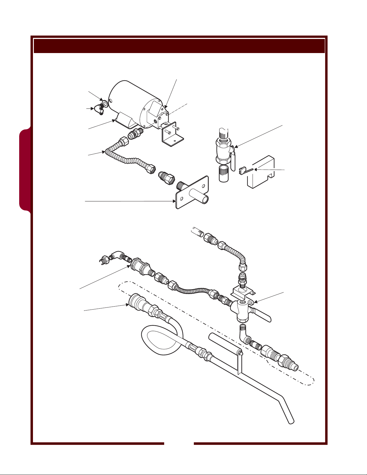
SERVICING INSTRUCTIONS (continued)
OPTIONAL FILTER WAND - ASSEMBLY
WASHER, FIBER
50177
FITTING, CONDUIT
3/8 x 90º 8706-109
MOTOR, FILTER
125/230V 1ø 50/60Hz
501205
WFAE-55FS
HOSE, SUCTION LINE
3/4” x 16.5” SS 502287
SUCTION LINE
FITTING 66720
PUMP, FILTER
501231
VALVE, BALL
1-1/4 NPT 69816
FRYPOT
MICROSWITCH
DRAIN SAFETY
64887
FROM PUMP
CHECK VALVE
3/8 NPT 66692
OIL WAND & HOSE
ASSY 23188
FRYPOT
VALVE 3-WAY
SS 504309
361 501219 Service Manual for WFAE-30F Fryer
18
Page 21

OPTIONAL FILTER WAND - DRAIN SAFETY SWITCH
DRAIN VALVE
MICROSWITCH
VALVE HANDLE
(CLOSED POSITION)
SERVICING INSTRUCTIONS (continued)
VALVE HANDLE ACTIVATES
DRAIN SAFETY SWITCH WHEN
IN THE “CLOSED” POSITION
WFAE-55FS
The MICRO SWITCH is in the control circuit for the heating element
contactor. The switch must be closed before the heating elements
can be energized.
When rotated to the CLOSED position, the valve handle will contact
the micro switch actuator, closing the switch.
Assemble the switch so that it is made when the valve handle is in
the fully closed position.
The drain safety switch is an
interlock to prevent energizing
the heating elements unless
the drain valve handle is in the
closed position.
361 501219 Service Manual for WFAE-30F Fryer
19
Page 22

SERVICING INSTRUCTIONS (continued)
WFAE-55F (MANUAL CONTROLS) HEATING ELEMENTS & ELECTRI CA L C OMPONENTS
WFAE-55F
RELAY, MERCURY
(OBSOLETE)
USE 504892
RELAY, E-SAFE
504892
CONTACTOR
3P 208V 40A
57779
SWITCH, TOGGLE
W/SEAL 64904
FACEPLATE, CONTROL
PANEL (DECAL) 502391
LIGHT, SIGNAL
AMBER 50516
SWITCH, ROCKER
POWER 69550
PLATE, SWITCH
ON-OFF 53192
CONNECTION BOX
HH
BUZZER 220V
64834
CONTROL PANEL
STRAIN RELIEF
1” NPT 500102
TERM BLOCK
50131
BEHIND CONTROL PANEL
TIMER 40MIN
240V 60Hz
68469
THERMO
FUSEHOLDER
10A 240V 54769
HI-LIMIT
66663
ELEMENT 8.5KW
500009 208V
500013 240V
KIT, ELEMENT
GASKET 66863
CLAMP, THERMOBULB
62504 (pk 4)
363 503043 Service Manual for WFAE-55F/FS Fryer
NUT, 8-32 x7/8” Alu
61974 (pk 10)
TERM BLOCK
FLAME SENSOR
53068
JUMPER, FLAME
SENSOR 54005
FUSE SC-10
10A (bx 4)
54871
20
KNOB, CONTROL
65653
KIT, CAPILLARY
FEED-THRU 66656
THERMO
TEMP CONTROL
66688
Page 23

SERVICING INSTRUCTIONS (continued)
WFAE-55FS (SOLID STATE CONTROLS) HEATING ELEMENTS & ELECTRICAL COMPONENTS
COOK CONTROLLER
FACEPLATE
(DECAL) 502417
SWITCH, ROCKER
POWER 69550
TRANSFORMER
208/240V : 24V
501454
502968
RELAY, MERCURY
(OBSOLETE)
USE 504892
RELAY, E-SAFE
504892
SPARK
QUENCHER
500688
CONTACTOR
3P 208V 40A
57780
RELAY, SOLID
STATE 501200
BEHIND CONTROL PANEL
ELEMENT 8.5KW
506258 208V 1ø
500009 208V 3ø
506259 240V 1ø
500013 240V 3ø
WFAE-55FS
363 503043 Service Manual for WFAE-55F/FS Fryer
CONTROL PANEL
CONNECTION BOX
HH
NUT, 8-32 x7/8” Alu
61974 (pk 10)
JUMPER, FLAME
SENSOR 54005
STRAIN RELIEF
1” NPT 500102
TERM BLOCK
50131
TERM BLOCK
FLAME SENSOR
53068
CLAMP, THERMOBULB
KIT, CAPILLARY
FEED-THRU 66656
THERMO
HI-LIMIT
66663
62504 (pk 4)
UNIT W/FILTER WAND
MICROSWITCH
DRAIN SAFETY
64887
KIT, ELEMENT
GASKET 66863
SONALERT
500974
FRAME BACKPLATE (EUROPEAN)
PROBE,
THERMOSTAT
501465
SPARK
QUENCHER
500688
TERMINAL BLOCK
4P 75A (EURO)
60310
21
Page 24

SERVICING INSTRUCTIONS (continued)
HEATING ELEMENT INSTALLATION INSTRUCTIONS
CAUTION
EXPOSED ELECTRIC
CIRCUITS
Disconnect electric power before
servicing heating element or
thermostats.
ELEMENT (ref)
GORTEX
GASKET
FRYPOT (ref)
BACKING PLATE
BELLEVILLE WASHER
(note orientation)
NUT
FRYPOT ELEMENT
NUT TIGHTENING SEQUENCE
Refer to drawings at left for assembly of Gortex gasket and Belleville
washer, and for nut tightening sequence.
1. Install 1/4” Gortex gasket (p/n 66864) over element studs.
DO NOT USE RTV!
Insert element through frypot, element and gasket on the inside
of frypot, and studs through the appropriate holes.
2. Install 1/4” Belleville washers with the high center away from
frypot, as shown (4 places).
3. Install four nuts finger tight.
4. Using a torque wrench, tighten all four nuts 1/2 turn at a time.
Work in a cross pattern to tighten each nut in sequence, until a
uniform reading of 70 inch-lbs is achieved on all four nuts.
5. To counter the slow compressibility characteristics of the Gortex
gasket:
a. Wait 2 minutes, then re-torque all four nuts to 70 inch-lbs.
b. Wait an additional two minutes, then re-torque all four nuts
to a uniform 70 inch-lbs.
12
3
GASKET BEHIND
VIEW FROM FRONT OF UNIT
4
363 503043 Service Manual for WFAE-55F/FS Fryer
22
Page 25

SERVICING INSTRUCTIONS (continued)
THERMOSTAT INSTALLATION INSTRUCTIONS
GREEN GASKET
NOTE: FRAGILE
FEED-THRU
BUSHING
17mm
OUTSIDE OF FRYPOT
BELLEVILLE WASHER
INSIDE OF FRYPOT
(p/n 69962)
LOCK NUT
17mm
CAPILLARY
WASHER
BLACK OIL SEAL
PAR T O F
1. Insert feed-thru bushing through green gasket, and insert both
through frypot wall. Slide Belleville washer over protruding
threads of bushing, with the high center of washer
frypot. Thread locknut onto bushing and tighten. Torque lock nut
to 30 inch pounds.
SAFETY CLAMP
ELEMENT
HOLDS BULB
CLEAR OF
ELEMENT
HI-LIMIT BULB: LEFT SIDE
TEMPERATURE CONTROL BULB: RIGHT SIDE (WFAE-55F ONLY)
3/8“
max.
BULB
TWO CLAMPS
HOLD BULB
ONE CLAMP HOLDS
CAPILLARY
PLACE CLAMPS WITHIN 3/8“
OF THE ENDS (WIDE PORTION)
OF BULB
2. Slip bulb of capillary tube through bushing. Mount bulb to center
portion of element with safety clamps. Positioning clamps within
3/8” of ends of the widest part of bulb. Route capillary tube
alongside of the element, but out of the way of cleaning brushes,
etc. Secure capillary tube near frypot end of element with a
safety clamp.
3. Seat washers and oil seal into bushing. Insert compression nut
into bushing, then torque to 30 - 40 inch-lbs.
COMPRESSION
NUT, 10mm
THERMOSTAT
CAPILLARY
away
from the
3/8“
max.
CAUTION
EXPOSED ELECTRIC
CIRCUITS
Disconnect electric power before
servicing heating element or
thermostats.
IMPORTANT:
17mm. hex head feed thru bushing
pictured at the left of drawing
MUST NOT
during assembly procedure.
Always support bushing with a box
wrench while tightening both lock
nut and compression nut to avoid
damage to green gasket!
NOTE:
capillary tube.
be allowed to rotate
Use care not to twist or kink
363 503043 Service Manual for WFAE-55F/FS Fryer
23
Page 26
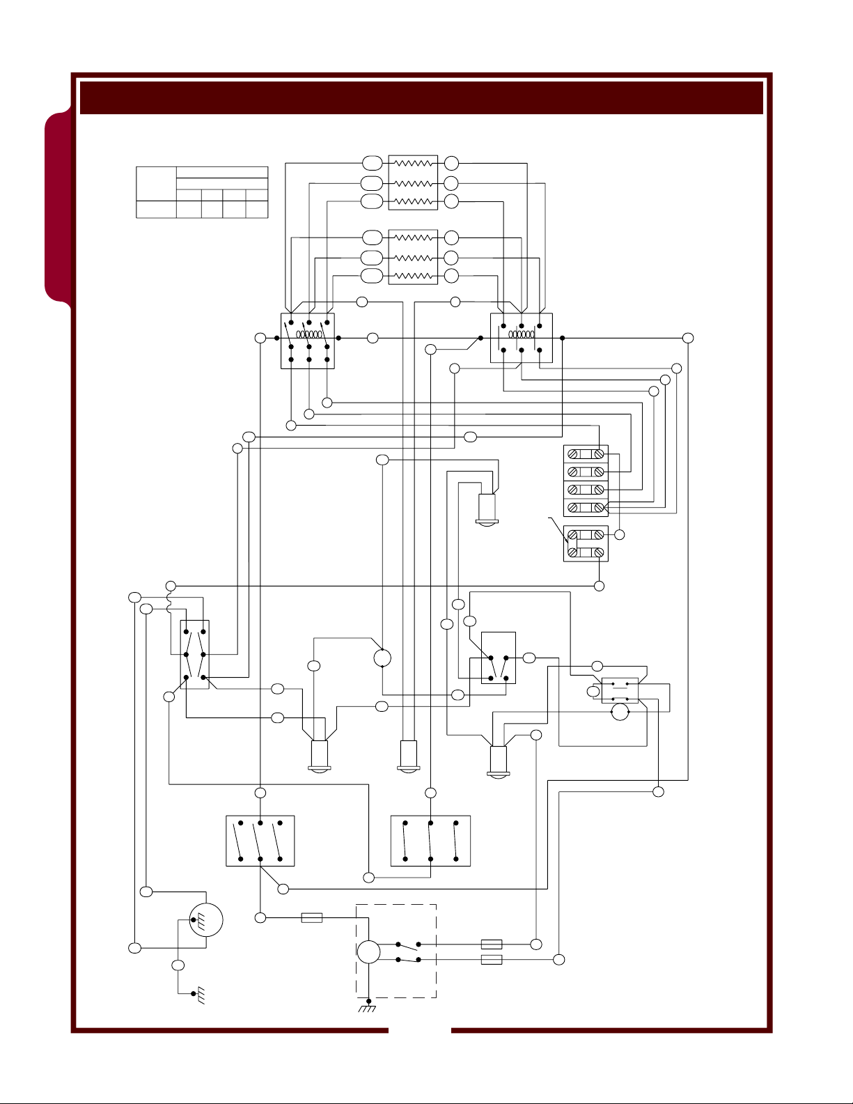
WIRING DIAGRAM
WFAE-55F
VOLT
50/60 HZ
208
240
REV. B P/N 49938
WIRING DIAGRAM FOR WFAE-55F FRYER - MANUAL CONTROLS
3Ø, 208 OR 240V, 17KW
FRYER RATING
L1
47.8
41.5
AMPS 3ø
L2
47.8
41.5
L3
47.2
40.9
1L1
1L2
1L3
8500W HEATING
ELEMENT(2)
1L1
1L2
1L3
1
2
3
1
2
3
10
15
3
2
9
28
27
26
12
POWER
SWITCH
C
21
1
29
25
POWER ON
LIGHT
30
MERCURY
RELAY
BUZZER
13
33
24
HEAT ON
LIGHT
11
14
9
BUZZER
LIGHT
35
BUZZER
23
SWITCH
32
34
COOK
LIGHT
CONTACTOR
28
TERMINAL
BLOCK
JUMPER
EXTERNAL
INTERLOCK
TERMINAL BLOCK
(REMOVE JUMPER
WHEN USING
EXTERNAL CONTROL)
20
17
31
22
TIMER
19
6
5
4
L1
L2
L3
7
8
363 503043 Service Manual for WFAE-55F/FS Fryer
8
27
FUSE 10A-SC
w/FUSE HOLDER
26
GREEN
36
FILTER
PUMP
18
LIMIT
SWITCHES
14
HI LIMIT
THERMOSTAT
BLACK
RED
17
18
15
TEMPERATURE
CONTROL
THERMOSTAT
19
16
BASKET LIFT
ACTUATOR
21
WHITE
GREEN
24
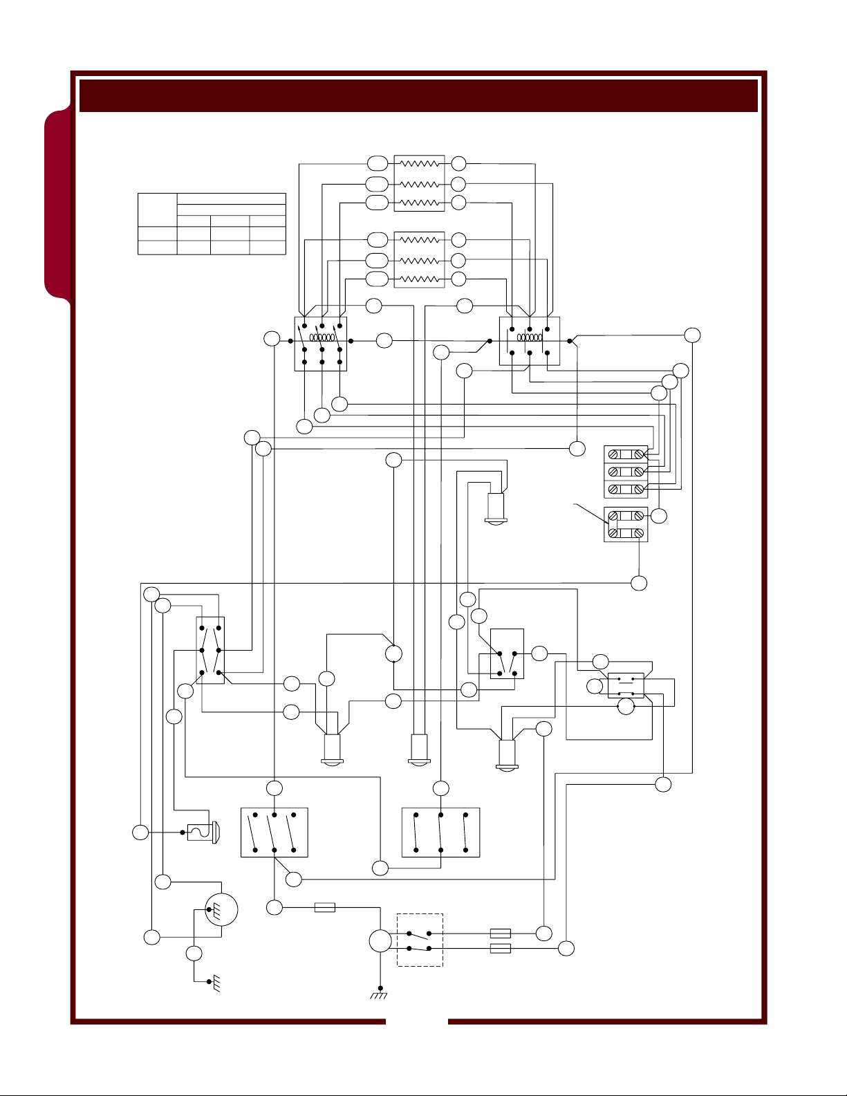
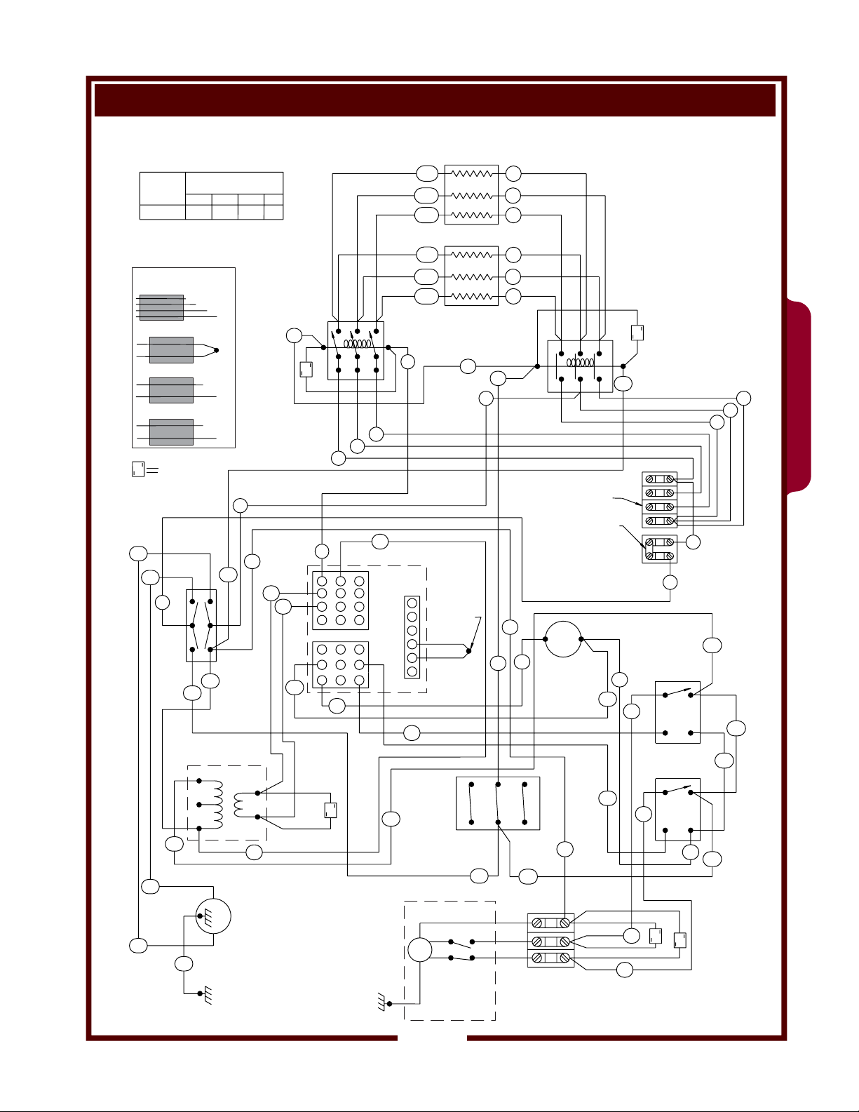
Page 27

WIRING DIAGRAM (continued)
WIRING DIAGRAM FOR WFAE-55FS FRYERS w/ SOLID STATE CONTROL
3Ø, 208 OR 240V, 17KW
VOLTS 3ø
50/60 HZ
REV. B P/N 301724
NOT UL LISTED
*
FOR SINGLE
PHASE
S
27
208
240
26
8
26
L1
SPARK
QUENCHER
(SNUBBER)
CONTROLLER
TRANSFORMER
30
FRYER RATING
AMPS
L2
4848
4242
28
C
POWER
SWITCH
25
24
240V
208V
1L1
3
10
-
UP
MERCURY
RELAY
11
6
5
4
3
-
2
+
1
19
30
1L2
1L3
8500W HEATING
ELEMENT(2)
1L1
1L2
1L3
THERMOCOUPLE
RED
WHITE
DOWN
THERMOSTAT
HI LIMIT
L3
47
41
15
S
2
1
9
11
16
12
13
+
22
COM
24V
10
CONTROLLER
123
654
8
9
7
101112
963
852
147
21
S
CONTACTOR
15
9
24
1
2
3
1
2
3
SAFETY
14
16
14
S
28
6
5
4
WFAE-55FS
SOLID STATE
RELAY
1
TOP
-
4
SOLID STATE
RELAY
1
BOTTOM
18
-
4
L1
L2
L3
7
8
30
2
AC
+
DC
AC
DC
31
33
3
32
2
+
3
23
*
TERMINAL
BLOCK
JUMPER
EXTERNAL INTERLOCK
TERMINAL BLOCK
(REMOVE JUMPER
WHEN USING
EXTERNAL CONTROL )
-
+
21
AUDIBLE
ALARM
16
23
31
22
17
20
UP
363 503043 Service Manual for WFAE-55F/FS Fryer
FILTER
PUMP
27
GREEN
34
BASKET LIFT
ACTUATOR
GREEN
LIMIT
SWITCHES
INSIDE
MOTOR
HOUSING
(COM)
(DN)
(UP)
WHITE
BLACK
RED
17
S
S
18
25
Page 28
WIRING DIAGRAM (continued)
WFAE-55F
VOLTS 3ø
50 HZ
380-415
P/N 300447 REV A
FRYER RATING
MAX AMPS
L1
27.0
26.5
L3L2
26.5
N
0.5
WIRING DIAGRAM FOR WFAE-55FEU
3Ø, 380-415V, 17KW 50 HZ
1L1
1L2
1L3
8500W HEATING
ELEMENT(2)
1L1
1L2
1L3
1
2
3
1
2
3
14
11
9
2828
BUZZER LIGHT
EXTERNAL INTERLOCK
TERMINAL BLOCK
(REMOVE JUMPER
WHEN USING
EXTERNAL CONTROL)
35
BUZZER
23
32
34
SWITCH
TERMINAL
BLOCK
JUMPER
20
17
CONTACTOR
L1
L2
L3
N
19
6
5
4
7
8
31
22
TIMER
363 503043 Service Manual for WFAE-55F/FS Fryer
10
MERCURY
RELAY
BUZZER
13
33
24
HEAT ON
LIGHT
15
3
2
1
9
8
27
26
POWER
SWITCH
C
21
POWER ON
30
29
25
LIGHT
COOK
RED
LIGHT
HI LIMIT
THERMOSTAT
17
18
LIMIT
SWITCHES
14
BLACK
15
TEMPERATURE
CONTROL
THERMOSTAT
26
FILTER
27
GREEN
36
PUMP
19
16
BASKET
LIFT
ACTUATOR
21
WHITE
GREEN
18
26
Page 29
WIRING DIAGRAM (continued)
WIRING DIAGRAM FOR WFAE-55FSEU
380-415V, 50HZ, 17KW
363 503043 Service Manual for WFAE-55F/FS Fryer
VOLTS 3ø
50 HZ
FRYER RATING
L1
380-415
REV. B P/N 303039
*
NOT UL LISTED
FOR SINGLE
PHASE
USE FERRITE CLAMPS
(P/N 302979 - 4 PLCS):
10
11
12
THERMOCOUPLE
19
20
SPARK
S
QUENCHER
(SNUBBER)
27
26
8
C
25
24
CONTROLLER
TRANSFORMER
240V
208
30
26
27
GREEN
34
MAX AMPS
L2
2424
13
21
22
9
28
POWER
SWITCH
FILTER
PUMP
L3
24
16
24V
10
1L1
N
5
1L2
1L3
8500W HEATING
ELEMENT(2)
1L1
1L2
1L3
MERCURY
15
S
RELAY
11
15
1
2
3
1
2
3
SAFETY
CONTACTOR
14
9
S
28
6
5
4
3
2
1
31
18
17
18
17
L1
L2
L3
N
8
SOLID STATE
RELAY
1
AC
TOP
-
DC
4
SOLID STATE
RELAY
1
AC
BOTTOM
-
DC
4
31
S
S
7
30
2
+
33
3
32
2
+
3
23
*
TERMINAL
BLOCK
JUMPER
11
12
321
987
13
12 11
+
741
22
COM
21
10
CONTROLLER
456
10
-
369
+
-
258
UP
EXTERNAL INTERLOCK
TERMINAL BLOCK
(REMOVE JUMPER
WHEN USING EXTERNAL
6
THERMOCOUPLE
5
4
RED
3
2
WHITE
1
14
CONTROL)
16
-
+
21
AUDIBLE
ALARM
22
DOWN
19
20
S
30
BASKET LIFT
ACTUATOR
THERMOSTAT
GREEN
HI LIMIT
LIMIT
SWITCHES
INSIDE
MOTOR
HOUSING
24
(COM)
(DN)
(UP)
23
WHITE
BLACK
RED
UP
16
WFAE-55FS
27
 Loading...