

Page 1
WELLS MANUFACTURING COMPANY
2 ERIK CIRCLE, P. O. Box 280
Verdi, NV 89439
Customer Service (775) 345-0444 Ext.502
fax: (775) 345-0569
www.wellsbloomfield.com
SERVICE MANUAL
SERVICE MANUAL
DROP-IN DISHWARE
DISPENSERS
AAA-AAA
MODELS
UTS & UTY
TROUBLESHOOTING
SUGGESTIONS
SERVICING
INSTRUCTIONS
EXPLODED VIEW
PARTS LIST
WIRING DIAGRAM
432
MODEL
UT, UTH
Includes:
Model UTH8
IMPORTANT:
DISSEMINATION OF THIS INFORMATION TO ANYONE OTHER THAN
WELLS AUTHORIZED SERVICE AGENTS IS STRICTLY PROHIBITED.
TECHNICAL CONTENT OF THIS MANUAL IS DESIGNED FOR
USE BY QUALIFIED PROFESSIONAL TECHNICIANS ONLY.
p/n 503849 Rev. (-) S432 061201 cps
WELLS MANUFACTURING PROPRIETARY INFORMATION.
Page 2
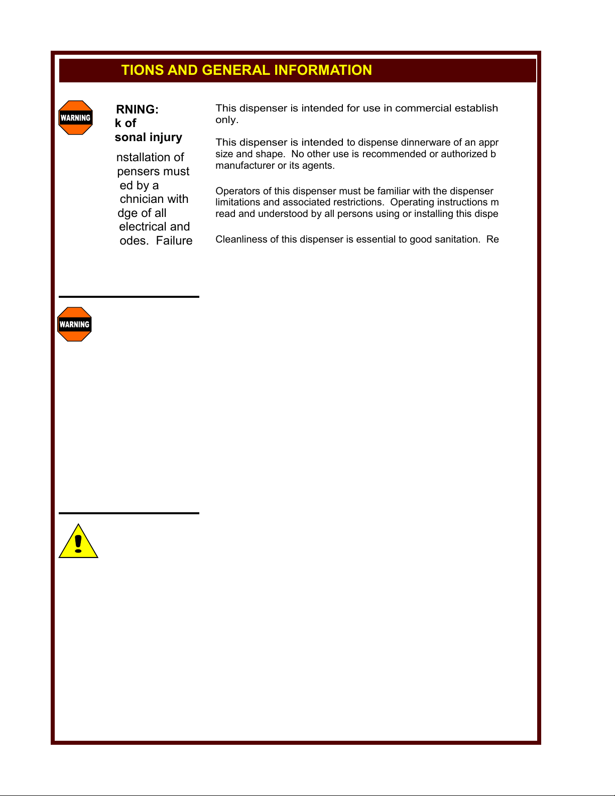
PRECAUTIONS AND GENERAL INFORMATION
WARNING:
Risk of
personal injury
Electrical installation of
heated dispensers must
be performed by a
qualified technician with
full knowledge of all
applicable electrical and
plumbing codes. Failure
can result in personal
injury and property
damage.
WARNING:
Electric
Shock hazard
All servicing requiring
access to non-insulated
electrical components
must be performed by a
qualified technician.
DO NOT open any
access panel which
requires the use of tools.
Failure to follow this
warning can result in
severe electrical shock.
CAUTION:
Risk of
Damage
DO NOT connect or
energize heated
dispensers until all
installation
instructions are read and
followed. Damage to the
dispenser will result if
these instructions are not
followed.
This dispenser is intended for use in commercial establishments
only.
This dispenser is intended
size and shape. No other use is
manufacturer or its agents.
to dispense dinnerware of an appropriate
recommended or authorized by the
Operators of this dispenser must be familiar with the dispenser use,
limitations and associated restrictions. Operating instructions must be
read and understood by all persons using or installing this dispenser.
Cleanliness of this dispenser is essential to good sanitation. Read and
follow all included cleaning instructions and schedules to ensure the
safety of the food product.
Disconnect heated dispensers from electrical power before performing
any maintenance or servicing.
DO NOT submerge heated dispensers in water. Do not splash or pour
water on, in or over any controls, control panel or wiring.
The technical content of this manual, including any wiring diagrams,
schematics, parts breakdown illustrations and/or adjustment
procedures, is intended for use by qualified technical personnel.
Any procedure which requires the use of tools must be performed by a
qualified technician.
This dispenser is made in the USA. Unless otherwise noted, this
dispenser has American sizes on all hardware.
xi
Page 3
TABLE OF CONTENTS
PRECAUTIONS & GENERAL INFORMATION xi
SPECIFICATIONS 1
FEATURES & OPERATING CONTROLS 2
WIRING DIAGRAM 2
OPERATION 3
EXPLODED VIEW & PARTS LIST 4
INTRODUCTION
This manual contains the information needed to properly service and repair this equipment.
MODEL DISH FLANGE REQ’D.
NO. DIA. DIA. CUTOUT*
UT4 UP TO 4” 7h ” 6d ” dia.
UT5 4d ”-5” 8h ” 7d ” dia.
UT57 5d ”-5H ” 9 ” 7d ” dia.
UT65 5L ”-6p ” 9H ” 8D ” dia.
UT7 6D ”-7h ” 10p ” 9l ” dia.
UT8 7L ”-8d ” 11L ” 10h ” dia.
UT9 8h ”-9d ” 12l ” 11h ” dia.
OPEN DROP-IN TUBES SHIELDED DROP-IN TUBES
UT10 9h ”-10h ” 13l ” 12l ” dia.
UT12 10l ”-12” 15d ” 14d ” dia.
UTS4 UP TO 4” 7h ” 6j ” dia.
UTS5 4d ”-5” 8h ” 7n ” dia.
UTS57 5d ”-5H ” 9 ” 8f ” dia.
UTS65 5L ”-6p ” 9H ” 8D ” dia.
UTS7 6D ”-7h ” 10p ” 9F ” dia.
UTS8 7L ”-8d ” 11L ” 10B ” dia.
UTS9 8h ”-9d ” 12l ” 11B ” dia.
UTS10 9h ”-10h ” 13l ” 12B ” dia.
UTS12 10l ”-12” 15d ” 14j ” dia.
* NOTE: Verify dimensions by referring to the Installation Instructions included with the dispenser.
For metric sizes refer to the Specification Sheet included with the dispenser.
UTH and UTY heated dispensers are shielded. UTS shielded dispensers are not heated.
MODEL DISH FLANGE REQ’D. WATTS AMPS
NO. DIA. DIA. CUTOUT*
UTH4 UP TO 4” 7h ” 6j ” dia. 240 2.0
UTH5 4d ”-5” 8h ” 7n ” dia. 240 2.0
UTH57 5d ”-5H ” 9 ” 8f ” dia. 240 2.0
UTH65 5L ”-6p ” 9H ” 8D ” dia. 300 2.5
UTH7 6D ”-7h ” 10p ” 9F ” dia. 300 2.5
UTH8 7L ”-8d ” 11L ” 10B ” dia. 300 2.5
UTH9 8h ”-9d ” 12l ” 11B ” dia. 300 2.5
UTH10 9h ”-10h ” 13l ” 12B ” dia. 500 4.2
UTH12 10l ”-12” 15d ” 14j ” dia. 500 4.2
120V 1ø HEATED DROP-IN TUBES
UTY4 UP TO 4” 7h ” 6j ” dia. 240 1.0
UTY5 4d ”-5” 8h ” 7n ” dia. 240 1.0
UTY57 5d ”-5H ” 9 ” 8f ” dia. 240 1.0
UTY65 5L ”-6p ” 9H ” 8D ” dia. 300 1.3
UTY7 6D ”-7h ” 10p ” 9F ” dia. 300 1.3
UTY8 7L ”-8d ” 11L ” 10B ” dia. 300 1.3
UTY9 8h ”-9d ” 12l ” 11B ” dia. 300 1.3
UTY10 9h ”-10h ” 13l ” 12B ” dia. 500 2.1
UTY12 10l ”-12” 15d ” 14j ” dia. 500 2.1
240V 1ø HEATED DROP-IN TUBES
SPECIFICATIONS
1
Page 4

FEATURES & OPERATING CONTROLS
CARRIAGE
1
2
3
CARRIAGE
SPRINGS
1
2
3
KEY
1
UT Series
2
UTS Series
3
UTH Series
4
UTY Series
PLATE GUIDES
1
2
3
4
4
FLANGE
1
2
3
4
POWER
SWITCH
3
4
POWER
INDICATOR
3
4
TEMPERATURE
ADJUSTMENT
4
OPEN
3
4
TUBE
1
2
3
4
SHIELD
2
3
4
POWER
CORD
3
4
HEATING
ELEMENT
3
4
Fig. 1 Features & Operating Controls - Drop-In Round Dinnerware Dispensers
WIRING DIAGRAM
SILICONE
SLEEVE
POWER
SWITCH
INDICATOR
LIGHT
2
THERMOSTAT
HEATING
ELEMENT
Page 5

OPERATION
OPERATING SUGGESTIONS
Load the dispenser with the appropriate size dinnerware.
Dinnerware which is too large may be broken or may jam the
carriage.
Dinnerware which is too small cannot be safely dispensed, and
may be broken or may jam the carriage.
Load no more than a 6” stack of dinnerware at a time.
Dispensers are designed for EMPTY dinnerware only.
For heated dispensers, turn the power switch to ON. When the switch
is ON the indicator light will glow.
Unused dispensers should be covered with the optional tube cover
(p/n 503985 or 503986).
TROUBLESHOOTING SUGGESTIONS
SYMPTOM
Carriage movement
erratic
Heated dispenser will not
heat (indicator light not on)
Heated dispenser will not
heat (indicator light on)
Heated dispenser indicator
light not lit (unit operating
normally)
Heated dispenser
temperature incorrect
POSSIBLE CAUSE
Debris between carriage and tube
Broken, disconnected or mis-matched
springs
Unit unplugged or circuit breaker
tripped or power switch OFF
Power plug or cord damaged
Power switch damaged or
disconnected
Thermostat set too low
Thermostat or wiring damaged
Heating element damaged or
disconnected
Indicator light damaged or
disconnected
Thermostat damaged
Thermostat not properly set
CAUTION:
Hot Surface
Exposed surfaces of heated
dispensers can be hot to the
touch and may cause burns.
CAUTION:
Pinch Hazard
Hold dinnerware by the sides
when loading the dispenser.
Holding dinnerware by the
bottom can allow fingers to
become trapped between the
plates and the dispenser
walls.
SUGGESTED ACTION
Remove from counter and
clean
Inspect springs— replace or
re-connect springs so that all
four sections are configured
the same
Check / reset circuit breaker
Make sure unit is plugged in
and power switch is ON
Check— replace or repair
Check— replace or repair
Set thermostat
Check— replace or repair
Check— replace or repair
Check— replace or repair
Check— replace or repair
Set thermostat
3
Page 6

EXPLODED VIEW & PARTS LIST
ITEM DESCRIPTION PART NO. USED ON SERIES QTY
1 RING, SPRING RETAINING UT, UTS, UTH, UTY 2
2 STAGE, PLATE CARRIAGE 4” 503987 UT, UTS, UTH, UTY 1
STAGE, PLATE CARRIAGE 5” 503988
STAGE, PLATE CARRIAGE 5-3/4” 503989
STAGE, PLATE CARRIAGE 6-1/2” 503990
STAGE, PLATE CARRIAGE 7” 503991
STAGE, PLATE CARRIAGE 8” 503992
STAGE, PLATE CARRIAGE 9” 503993
STAGE, PLATE CARRIAGE 10” 503994
STAGE, PLATE CARRIAGE 12” 503995
3 COLLAR, PLATE CARRIAGE UT, UTS, UTH, UTY 1
4 RING, INNER SUPPORT UT, UTS, UTH, UTY 1
5 SPACER, INNER SUPPORT UT, UTS, UTH, UTY 5
6 SPRING, COARSE NON-HEATED 503966 UT, UTS 20
SPRING, FINE NON-HEATED 503960 UT, UTS
SPRING, COARSE HEATED 503961 UTH, UTY
SPRING, FINE HEATED 503950 UTH, UTY
4
Page 7

ITEM DESCRIPTION PART NO. USED ON SERIES QTY
7 GLIDE, PLATE CARRIAGE, TEFLON 503952 UT, UTS, UTH, UTY 8
8 GUIDE, PLATE PLASTIC 503951 UT, UTS, UTH, UTY 3
9 ASSY, FRAME NON-HEATED UT, UTS 1
ASSY, FRAME HEATED UTH, UTY
10 SHIELD, NON-HEATED UT, UTS 1
SHIELD, HEATED UTH, UTY
11 BOTTOM, SHIELD NON-HEATED UT, UTS 1
BOTTOM, SHIELD HEATED UTH, UTY
20 ASSEMBLY, CONTROL
21 SWITCH, POWER 503959 UTH, UTY 1
22 INDICATOR, POWER RED 120 VOLT 503957 UTH 1
INDICATOR, POWER RED 240 VOLT 503964 UTY
23 TROUGH, WIRING UTH, UTY 1
24 BRACKET, TEMP CONTROL UTH, UTY 1
25 CONTROL, TEMP BI-METAL 503956 UTH, UTY 1
31 ELEMENT, 120 VOLT, 4”, 5”, 5-3/4” 503953 UTH 1
ELEMENT, 120 VOLT, 6-1/2”, 7”, 8”, 9” 503967
ELEMENT, 120 VOLT, 10”, 12” 503969
ELEMENT, 240 VOLT, 4”, 5”, 5-3/4” 503962 UTY
ELEMENT, 240 VOLT, 6-1/2”, 7”, 8”, 9” 503968
ELEMENT, 240 VOLT, 10”, 12” 503970
32 ASSY, POWER CORD 120 VOLT 503983 UTH 1
ASSY, POWER CORD 240 VOLT 503984 UTY
33 STRAIN RELIEF UTH, UTY 1
50 PLATE COVER, 7” - 8” TUBE 503985 OPTIONAL
PLATE COVER, 9” - 10” TUBE 503986 OPTIONAL
a SCREW, PH 10-24 x 1-1/2” SS UT, UTS, UTH, UTY 5
b SCREW, PH #8 x 1/4” SMS SS UT, UTS, UTH, UTY 8
c SCREW, #12 x 3” RHWS Zi UT, UTS, UTH, UTY 3
d NUT, 10-32 SS UTH, UTY 2
e NUT, 10-32 x 7/8” Alum UTH, UTY 2
f NUT, KEP 10-24 SS UT, 5
UTS, UTH, UTY 8
g RIVET, BLIND 3/32 x 1/4 Alum UTS 4
UTH, UTY 6
h RETAINER, WIRING UTH, UTY 3
5
Page 8

IMPORTANT:
WELLS MANUFACTURING PROPRIETARY INFORMATION.
DISSEMINATION OF THIS INFORMATION TO ANYONE OTHER THAN
WELLS AUTHORIZED SERVICE AGENTS IS STRICTLY PROHIBITED.
TECHNICAL CONTENT OF THIS MANUAL IS DESIGNED FOR
USE BY QUALIFIED PROFESSIONAL TECHNICIANS ONLY.
WELLS MANUFACTURING COMPANY
DIVISION OF CARRIER REFRIGERATION
2 ERIK CIRCLE, P. O. Box 280
Verdi, NV 89439
Customer Service (775) 345-0444 Ext.502
fax: (775) 345-0569
www.wellsbloomfield.com
 Loading...