

Page 1
Model RW2HD
WELLS MANUFACTURING
265 Hobson Street, Smithville, Tennessee 37166
telephone: 314-678-6314
fax: 314-781-2714
www.wells-mfg
.com
OWNERS MANUAL
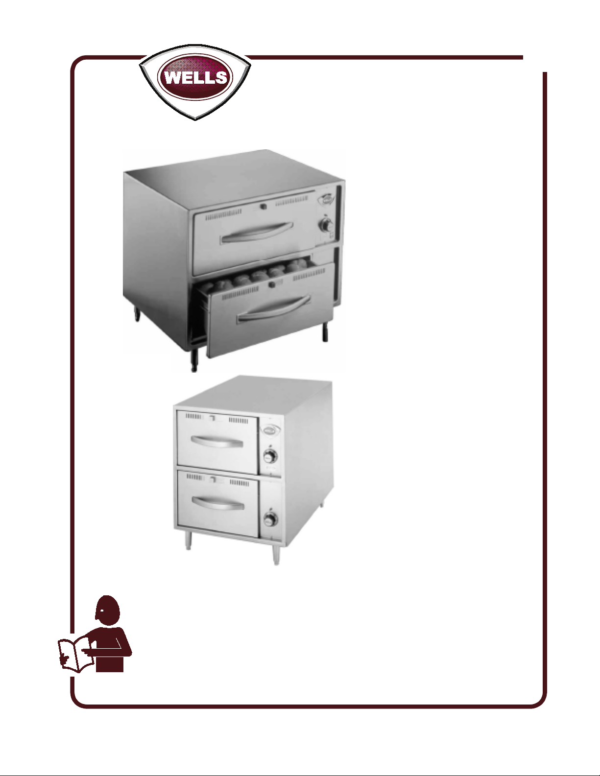
FREE STANDING
DRAWER WARMERS
with THERMOSTATIC
CONTROL
MODELS
RW1HD
RW2HD
RW3HD
041
RWN1
RWN2
RWN3
Includes
INSTALLATION
USE & CARE
EXPLODED VIEW
Model RWN2
IMPORTANT: DO NOT DISCARD THIS MANUAL
This manual is considered to be part of the appliance and is to be given to the OWNER or
MANAGER of the restaurant, or to the person responsible for TRAINING OPERATORS of
this appliance. Additional manuals are available from your WELLS DEALER.
THIS MANUAL MUST BE READ AND UNDERSTOOD BY ALL PERSONS USING OR
INSTALLING THIS APPLIANCE. Contact your WELLS DEALER if you have any
questions concerning installation, operation or maintenance of this equipment.
PARTS LIST
WIRING DIAGRAM
2M-303335 Rev. G
03/18
Page 2

LIMITED EQUIPMENT WARRANTY
Wells Manufacturing warranties new products to be free from defects
in material and/or workmanship for a period of one [1] year from the
date of original installation, except as noted below. Defects that occur
as a result of normal use, within the time period and limitations defined
in this warranty, will at Wells’ discretion have the parts replaced or
repaired by Wells or a Wells-authorized service agency.
THIS WARRANTY IS SUBJECT TO ALL LISTED CONDITIONS.
Repairs performed under this warranty are to be performed by a Wellsauthorized service agency. Wells will not be responsible for charges
incurred or service performed by non-authorized repair agencies.
In all cases, the nearest Wells-authorized service agency must be used.
Wells will be responsible for normal labor charges incurred in the repair
or replacement of a warrantied product within 50 miles (80.5 km) of
an authorized service agency. Time and expense charges for anything
beyond that distance will be the responsibility of the owner. All labor
will need to be performed during regular service hours. Any overtime
premium will be charged to the owner. For all shipments outside the
U.S.A. and Canada, please see the International Warranty for specific
details.
It is the responsibility of the owner to inspect and report any shipping
damage claims, hidden or otherwise, promptly following delivery.
No mileage or travel charges will be honored on any equipment that is
deemed portable. In general, equipment with a cord and plug weighing
less than 50 lb. (22.7 kg) is considered portable and should be taken or
shipped to the closest authorized service agency, transportation prepaid .
CO NTAC T
Should you require any assistance regarding the operation or
maintenance of any Wells equipment; write, phone, fax or email
our service department. In all correspondence mention the
model number and the serial number of your unit, as well as
the voltage or type of gas you are using.
Business hours are 8:00 a.m. to 4:30 p.m. Central Standard Time
Telephone 314.678.6314
Fax 314.781.2714
Email customerservice@star-mfg.com
www.wells-mfg.com
WARRA
THE FOLLOWING WILL NOT BE COVERED UNDER WARRANTY.
• Any product which has not been installed, cleaned, maintained,
or used in accordance with the directions published in the appropriate
installation sheet and/or owner’s manual as well as national and local
codes, including incorrect gas or electrical connection. Wells is not liable
for any unit which has been mishandled, abused, misapplied, subjected
to chlorides, harsh chemicals, or caustic cleaners, damaged from
exposure to hard water, modified by unauthorized personnel, damaged
by flood, fire, or other acts of nature [or God], or which have an altered
or missing serial number.
• Installation, labor, and job checkouts, calibration of heat controls, air
and gas burner/bypass/pilot adjustments, gas or electrical system
checks, voltage and phase conversions, cleaning of equipment,
or seasoning of griddle surface.
• Replacement of fuses or resetting of circuit breakers, safety controls,
or reset buttons.
• Replacement of broken or damaged glass components, quartz heating
elements, and light bulbs.
• Labor charges for all removable parts in gas charbroilers and hotplates,
including but not limited to burners, grates, and radiants.
• Any labor charges incurred by delays, waiting time, or operating
restrictions that hinder a service technician’s ability to perform service.
• Parts that fail or are damaged due to normal wear or labor for
replacement of Items that can easily be replaced during a daily cleaning
routine. such as but not limited to silicone belts, PTFE non-stick sheets,
knobs, control labels, bulbs, fuses, quartz heating elements, baskets,
racks, and grease drawers.
• Components that should be replaced when damaged or worn, but have
been field-repaired instead [eg. field-welded fry pots].
• Any loss of business or profits.
ADDITIONAL WARRANTIES
Specialty/chain specific versions may also have additional and/or
extended warranties.
NTY EXCLUSIONS
PRODUCTS PARTS LABOR
universal ventless hoods 2 years 1 year
canopy hoods 2 years 1 year
“Cook’n Hold” equipment [HW10,
HWSMP, LLSC7, LLSC7WA, LLSC11,
2 years 1 year
an d LLSC 1 1WA]
cast iron grates, burners, and burner
shields
original Wells parts sold to repair
Wells equipment
1 year
90 days
Service First 1 year
The fore going warrant y is in lieu of any and a ll other warranti es expresse d or implied and c onstitutes the e ntire warranty. 2M-Z22393 • Rev A • 02.2018
Page 3
TABLE OF CONTENTS
WARRANTY
SPECIFICATIONS 1
FEATURES & OPERATING CONTROLS 2
PRECAUTIONS & GENERAL INFORMATION 3
AGENCY LISTING INFORMATION 3
INSTALLATION 4
OPERATION 6
CLEANING INSTRUCTIONS 8
TROUBLESHOOTING SUGGESTIONS 9
MAINTENANCE INSTRUCTIONS 10
EXPLODED VIEW & PARTS LIST 11
WIRING DIAGRAM 13
PARTS & SERVICE 17
CUSTOMER SERVICE DATA 17
INTRODUCTION
Thank You for purchasing this Wells Manufacturing appliance.
Proper installation, professional operation and consistent maintenance of this appliance will ensure that it
gives you the very best performance and a long, economical service life.
This manual contains the information needed to properly install this appliance, and to use and care for the
appliance in a manner which will ensure its optimum performance.
M041 p/n 2M-303335 Owners Manual Free-Standing Drawer Warmer
MODELS
RW1HD, RWN1
RW2HD, RWN2
RW3HD, RWN3
SPECIFICATIONS
VOLTS
50/60 Hz 1ø
120 VAC 450 W 3.8 NEMA-5-15P
208/240 VAC 338/450 W 1.6/1.9 NEMA 6-15P
120 VAC 900 W 7.5 NEMA-5-15P
208/240 VAC 676/900 W 3.3/3.8 NEMA 6-15P
120 VAC 1350 W 11.3 NEMA-5-15P
208/240 VAC 1014/1350 W 4.9/5.6 NEMA 6-15P
WATTS AMPS
1
POWER
CORD
Page 4
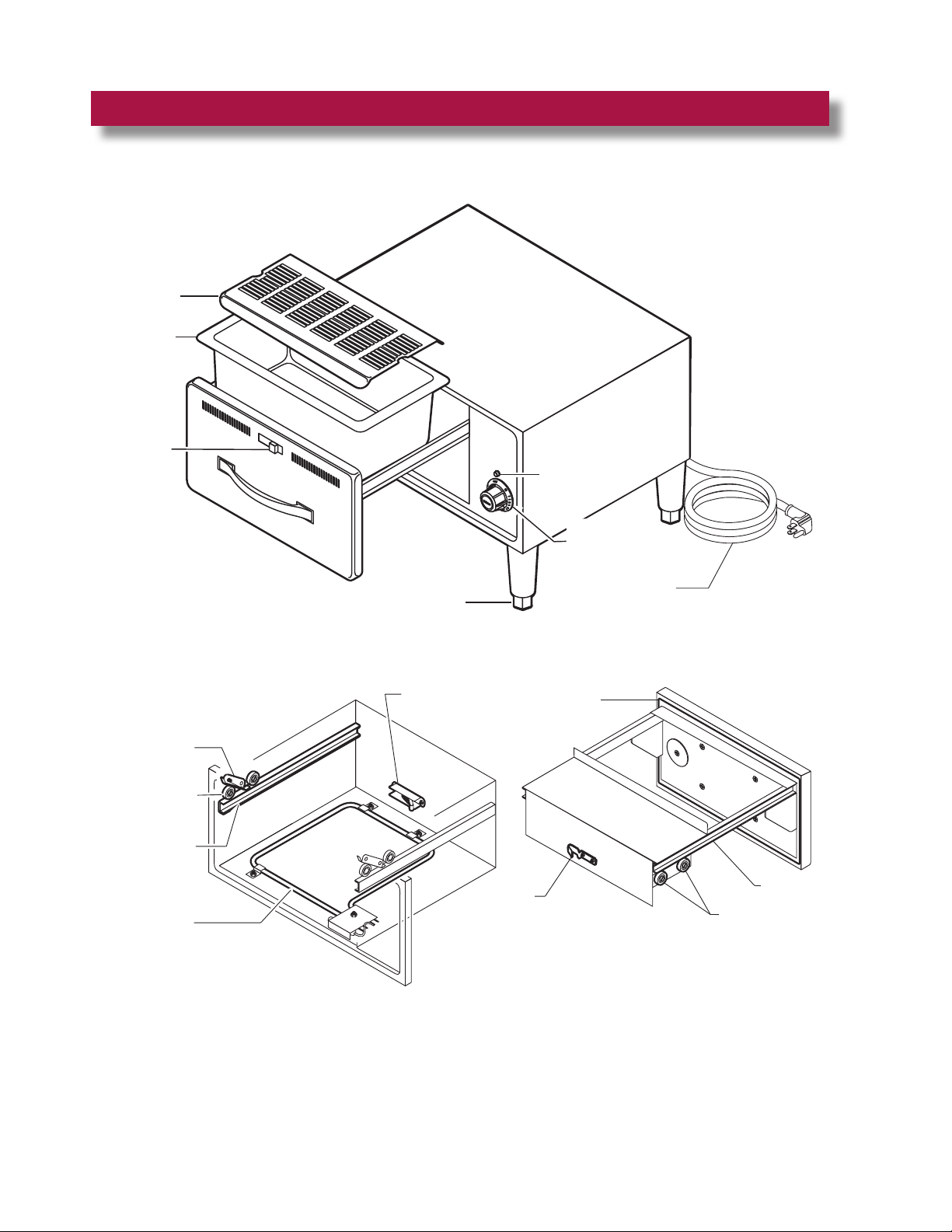
FEATURES & OPERATING CONTROLS
HUMITROL
RACK
DRAWER
INSERT PAN
AIR VENT
CONTROL
HEATING
INDICATOR
TEMPERATURE
CONTROL
DRAWER
STOP
DRAWER
ROLLER
DRAWER
SLIDE
HEATING
ELEMENT
ADJUSTABLE
LEG
ROLLER
CATCH
DRAWER
CATCH
DRAWER
GASKET
POWER CORD
DRAWER
ROLLERS
DRAWER
SLIDE
IL2929
2
Page 5

PRECAUTIONS AND GENERAL INFORMATION
This appliance is intended for use in commercial establishments only.
This appliance is intended to prepare food for human consumption. No
other use is recommended or authorized by the manufacturer or its
agents.
Operators of this appliance must be familiar with the appliance use,
limitations and associated restrictions. Operating instructions must be
read and understood by all persons using or installing this appliance.
Cleanliness of this appliance is essential to good sanitation. Read and
follow all included cleaning instructions and schedules to ensure the
safety of the food product.
Disconnect this appliance from electrical power before performing any
maintenance or servicing.
DO NOT submerge this appliance in water. This appliance is not jet
stream approved. Do not direct water jet or steam jet at this appliance,
or at any control panel or wiring. Do not splash or pour water on, in or
over any controls, control panel or wiring. Do not wash oor around
this appliance with water or steam jet.
Exposed surfaces of this appliance can be hot to the touch and may
cause burns.
Heating element will be very hot when in use. Contact may cause
serious burns.
The technical content of this manual, including any wiring diagrams,
schematics, parts breakdown illustrations and/or adjustment
procedures, is intended for use by qualied technical personnel.
Any procedure which requires the use of tools must be performed by a
qualied technician.
This manual is considered to be a permanent part of the appliance.
This manual and all supplied instructions, diagrams, schematics,
parts breakdown illustrations, notices and labels must remain with the
appliance if it is sold or moved to another location.
This appliance is made in the USA. Unless otherwise noted, this
appliance has American sizes on all hardware.
WARNING:
ELECTRIC
SHOCK HAZARD
All servicing requiring
access to non-insulated
electrical components must
be performed by a factory
authorized technician.
DO NOT open any access
panel which requires the use
of tools. Failure to
follow this warning can
result in severe electrical
shock.
CAUTION:
RISK OF
DAMAGE
DO NOT connect or
energize this appliance
until all installation
instructions are read and
followed. Damage to the
appliance will result if
these instructions are not
followed.
CAUTION:
HOT SURFACE
Exposed surfaces can be
hot to the touch and may
cause burns.
This appliance conforms to NSF Standard 4 for sanitation only if
installed in accordance with the supplied Installation Instructions and
maintained according to the instructions in this manual.
IMPORTANT:
RW- models are NOT NSF approved for potentially hazardous foods.
This appliance is and Listed under UL File E6070 for 120V,
208V and 240V.
M041 p/n 2M-303335 Owners Manual Free-Standing Drawer Warmer
3
AGENCY LISTING INFORMATION
STD 4
E6070
E6070
Page 6
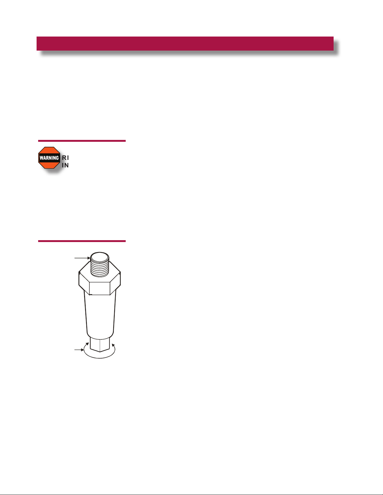
INSTALLATION
IL2926
MOUNTS INTO
THREADED
HOLES IN
WARMER
FRAME
TURN BOTTOM
PORTION TO
ADJUST
NOTE: DO NOT discard
the carton or other packing
materials until you have
inspected the appliance for
hidden damage and tested
it for proper operation.
Refer to SHIPPING
DAMAGE CLAIM
PROCEDURE on the inside
front cover of this manual.
WARNING:
RISK OF
INJURY
Installation procedures
must be performed by a
qualied technician with full
knowledge of all applicable
electrical and plumbing
codes. Failure can result in
personal injury and property
damage.
UNPACKING & INSPECTION
Carefully remove the appliance from the carton. Remove all protective
plastic lm, packing materials and accessories from the Appliance
before connecting electrical power or otherwise performing any
installation procedure.
Carefully read all instructions in this manual and the Installation
Instruction Sheet packed with the appliance before starting any
installation.
Read and understand all labels and diagrams attached to the
appliance.
Carefully account for all components and accessories before discarding
packing materials. Store all accessories in a convenient place for later
use.
COMPONENTS
1 - 3 ea. DRAWERS (qty. depends on model)
1 - 3 ea. HUMITROL RACKS (if ordered with unit)
SETUP
Install adjustable legs or optional casters, one on each corner of the
appliance, in the holes provided.
Verify that the unit sits rmly on ALL FOUR legs. With a spirit level,
check that the appliance is level front-to-back and side-to-side. With
the adjustable legs, adjust as required to level the appliance. All four
legs must be adjusted to rmly contact the oor in order to prevent
tipping.
If drawers were removed during installation, install drawer(s) in unit:
a. Check the roller catch inside the cabinet. The spring-loaded roller
arm must be extended.
b. With the front of the drawer assembly tipped downward,
engage the roller on the drawer with the cabinet drawer slide.
c. Raise the drawer to the horizontal position until the drawer-
mounted slide engages the dual roller assembly on the cabinet.
d. Slide the drawer in until the catch engages. The drawer should
remain tightly closed.
e. Slide the drawer out. The drawer stop should prevent the
drawer from coming all of the way out.
f. Install drawer insert pans.
Avoid storing ammable or combustible materials in, on or near the
appliance.
4
Page 7

INSTALLATION (continued)
GROUND
PIN
NEMA 5-15P
PLUG
NEMA 5-15R
RECEPTACLE
IL2927
IL2928
NEMA 6-15P
PLUG
GROUND
PIN
NEMA 6-15R
RECEPTACLE
ELECTRICAL
Refer to electrical specications on page 1. Circuit must meet or
exceed the amperage and wattage requirements listed.
120 Volt units require a properly grounded NEMA 5-15R receptacle:
208/240 Volt units require a properly grounded NEMA 6-15R receptacle:
WARNING:
SHOCK HAZARD
All servicing requiring
access to non-insulated
electrical components must
be performed by a factory
authorized technician.
DO NOT open any access
panel which requires the use
of tools. Failure to follow this
warning can result in severe
electrical shock.
CAUTION:
RISK OF
DAMAGE
DO NOT connect or energize
this appliance until all
installation instructions are
read and followed. Damage
to the appliance will result
if these instructions are not
followed.
CAUTION:
SHOCK HAZARD
The ground prong of the
power cord is part of a
system designed to protect
you from electric shock in the
event of internal damage.
DO NOT cut off the large
round ground prong, or twist
a blade to t an existing
receptacle.
IMPORTANT:
Contact a licensed electrician
to install and connect
electrical power to the
appliance.
IMPORTANT:
Damage due to being
connected to the wrong
voltage or phase is NOT
covered by warranty.
M041 p/n 2M-303335 Owners Manual Free-Standing Drawer Warmer
5
Page 8

OPERATION
HEATING
INDICATOR
THERMOSTATIC
TEMPERATURE
CONTROL
IL2930
CAUTION:
HOT SURFACE
Exposed surfaces can be hot
to the touch and may cause
burns.
NOTE:
The chart below is intended
as a guide ONLY. Your
own experience with this
appliance, type of foods
and method of operation will
enable you to determine the
temperature control and air
vent settings best suited to
your operation.
HEATING OPTIONS
1. Moist heat with Humitrol Rack:
a. MOIST operation prevents food from drying out as heat is
applied to the warming chamber.
b. To set for MOIST operation, remove the Humitrol Rack from
bottom of drawer insert pan and carefully pour approximately
2 quarts of water (½” depth) into the pan. Reinstall rack.
c. When the drawer is closed, the Humitrol Rack allows water
vapor to rise through the stored product in the drawer. The
Humitrol Rack also decreases the sloshing effect of the water
in the pan when the drawer is opened.
d. Place the food directly on the rack. The rack is designed to
support the food off of the steam vents, where water droplets
may form.
e. Check the water level in the pan periodically, and add water
when necessary.
f. Set the front air vent between fully closed and half-open.
Actual setting will depend upon the type and amount of product
stored in the drawer, the temperature setting, and the
frequency with which the drawer is opened.
2. Moist heat with pans:
a. This Wells warmer is designed to accommodate any
combination of standard-size, steam table pans.
b. Place a small amount of water in drawer pan. Place the steam
table pans in the drawer pan.
c. Check the water level in the pan periodically, and add water
when necessary.
3. Dry heat:
a. For some applications, you may want to store previously
prepared foods in a dry-heat environment. To do so, place the
food directly into the empty (i.e. no water) drawer pan.
OPERATING CHART FOR DRAWER WARMERS
PRODUCT TYPE
Hard Rolls 160-185ºF 71-85°C Dry 7-8 Full Open
Soft Rolls 150-175ºF 65-79°C Moist 6-7 Open - ½
Vegetables 175-185ºF 79-85°C Moist 7-8 Open - ½
Meats 165-185ºF 74-85°C Dry 6-8 Full Open
Fish 165-185ºF 74-85°C Moist 6-8 Closed
Casseroles 150-175ºF 65-79°C Dry 6-7 Full Open
Pies, Desserts 160-185ºF 65-85°C Dry 6-7 Full Open
Taco Shells 150-170ºF 65-76°C
Corn Chips 150-170ºF 65-76°C 4-6 Full Open
RECOMMENDED
STORAGE TEMP.
TYPE OF HEAT
do not put water
in the pan
CONTROL
SETTINGS
4-6 Full Open
6
AIR VENT
SETTINGS
Page 9

OPERATION (continued)
OPERATION
1. Determine the type of food to be warmed.
2. Refer to the chart on page 6 to determine the type of heat required.
3. Set the air vent control for the type of heat, and rotate the
thermostat knob to the temperature setting desired.
4. Allow warmer to pre-heat for approximately 30 minutes before use.
DO’S and DON’TS
1. DO Always use a drawer pan.
DO NOT Place food directly into the warmer cavity.
2. DO Check water level in moist-operation warmer
frequently during use.
DO Use a Humitrol Rack or Insets to hold food for moist
operation.
3. DO Use warm water to add to the pan during moist
operation.
DO NOT Put ice into a warmer pan. Ice in the pan will cause
condensation on the inside of the warmer cavity.
CAUTION:
HOT SURFACE
Exposed surfaces can be hot
to the touch and may cause
burns.
CAUTION:
SHOCK HAZARD
DO NOT splash or pour water
onto control panel or wiring.
IMPORTANT:
DO NOT place food directly
into the warmer cavity.
Always use a drawer pan.
IMPORTANT:
DO NOT put ice into a warmer
pan. Ice in the pan will
cause condensation on the
inside of the warmer cavity.
Damage caused by this type of
condensation is NOT covered
by warranty.
M041 p/n 2M-303335 Owners Manual Free-Standing Drawer Warmer
7
Page 10

CLEANING INSTRUCTIONS
IL2931
CAUTION:
SHOCK HAZARD
Disconnect appliance from
electric power before cleaning.
CAUTION:
HOT SURFACE
Exposed surfaces can be hot
to the touch and may cause
burns. Allow appliance to cool
before cleaning.
PRECAUTIONS: Turn control knob to OFF.
Allow drawers to cool before proceeding.
Remove drawer pans and Humitrol racks.
FREQUENCY: Minimum - Daily
TOOLS: Warm water and mild detergent
Clean cloth or sponge
1. Remove drawers from warmer:
a. Pull warmer drawer out until fully extended.
b. Slide nger along left and right slide rail until you reach the
latches (located at the front end of the cabinet-mounted rails)
Press down on both left and right latch.
c. Pull drawer away from warmer.
2. Clean drawers, drawer pans, Humitrol Racks and/or insets with warm
water and mild detergent.
Rinse all components thoroughly with clear water.
Dry all components prior to reinstalling them in warmer.
3. Sweep crumbs and other debris from warmer cavity.
4. Clean the outside of the unit by wiping with a clean cloth or sponge,
warm water and mild detergent. Dry with a clean cloth, then wipe with
a polish formulated for stainless steel.
5. It is important to keep the slide rails clear and free from debris.
Periodic cleaning of the slide rails and other adjoining parts is
necessary to assure smooth drawer operation.
6. Check drawer rollers. Be sure they roll freely and that the slide rails
are free from debris.
7. Be sure cabinet-mounted drawer catch roller is “up”, then re-install
drawers.
8
Page 11

TROUBLESHOOTING SUGGESTIONS
SYMPTOM POSSIBLE CAUSE SUGGESTED REMEDY
Warmer unplugged Plug warmer into appropriate receptacle
No lights or heat (all
drawers)
No heat (one drawer)
Food dries out
Food gets soggy
Drawer falls open
Drawer falls out when
opened
Circuit breaker off or tripped Reset circuit breaker
Internal damage
Contact an Authorized Wells Service
Agency for repairs.
Temperature control not set Set for desired temperature.
Internal damage
Humidity control (air vent) not set
Contact an Authorized Wells Service
Agency for repairs.
OPEN air vent for dry operation.
CLOSE air vent for moist operation.
Water in pan evaporated or low Add water to pan.
Food contacting water Use a Humitrol Rack
Water level too high
Humidity control (air vent) not set
Catch roller not extended before
closing drawer
Drawer catch damaged
Water should be no more than 1/2”
deep
OPEN air vent for dry operation.
CLOSE air vent for moist operation.
Be sure catch roller is extended before
installing drawer.
Contact an Authorized Wells Service
Agency for repairs.
Drawer stop dirty Clean and lubricate drawer stop
Drawer stop damaged
Contact an Authorized Wells Service
Agency for repairs.
M041 p/n 2M-303335 Owners Manual Free-Standing Drawer Warmer
9
Page 12

MAINTENANCE INSTRUCTIONS (continued)
1
6
5
4
2
3
1
1
2
2
8
9
3
7
IL2932
CAUTION:
SHOCK HAZARD
Disconnect appliance from
electric power before cleaning.
CAUTION:
HOT SURFACE
Exposed surfaces can be hot
to the touch and may cause
burns. Allow appliance to cool
before servicing.
ADJUSTMENTS AND LUBRICATION
PRECAUTIONS: Turn control knob to OFF. Unplug warmer
Allow drawers to cool before proceeding.
Remove drawer pans and Humitrol racks
FREQUENCY: Minimum - monthly.
Every 2 weeks recommended.
TOOLS: Screwdrivers, Phillips (+) and at blade (-).
Nut drivers, 3/8” and 7/16”.
Food-grade lubricant.
1. Check slides on cabinet and drawers for cleanliness.
2. Check all rollers on cabinet and drawers for cleanliness and
tightness. Lubricate.
3. Check cabinet drawer stops for operation. Stops must “snap” down
positively. Clean and adjust as required.
4. Check cabinet heating element fasteners for tightness.
5. Check all cabinet drawer catches for tightness and operation.
Lubricate. Be certain roller is “out” before attempting to install drawer.
6. Check thermostat thermo-bulb and capillary tube for condition.
Thermo-bulb must be securely mounted in the appropriate holder.
Arrange repairs for damaged thermo-bulb or capillary tube.
7. Check drawer faceplate and handle fasteners for tightness.
8. Check drawer catch clip for tightness.
9. For drawers equipped with gaskets, examine condition of gasket.
Arrange repairs for torn or damaged gaskets.
10. Reinstall drawers and check for proper operation.
Procedure is complete.
10
Page 13

WIRING DIAGRAM
M041 p/n 2M-303335 Owners Manual Free-Standing Drawer Warmer
11
Page 14

EXPLODED VIEW & PARTS LIST: RW1HD, RW2HD, RW3HD
DRAWER ASSEMBLY - COMMON TO ALL HD VERSIONS
1
2
10
8
7
6
9
3
5
4
CAVITY and CABINET INERIOR - COMMON TO ALL HD VERSIONS
25
14
10
24
23
15
9
11
12
13
22
12
(optional thermometer)
16
17
19
18
21
20
IL2251b
12
Page 15

EXPLODED VIEW & PARTS LIST
RW1HD, RW2HD, RW3HD, DRAWER WARMER
Fig No Part No. Description
1 WS-20624 RACK HUMITROL RWS (OPTIONAL)
2 C8-46840 PAN INSERT DRAWER RWHD
3 WS-67096 DRAWER ASSY KIT RWHD
4 C8-32112 HANDLE RW DRAWER SRW320
5 WS-51796 KNOB SQUARE ROLL WARMER VENT
6 C8-49251 SLIDE VENT ASSY RWN
7 2C-35530 SCREW, 8-32 X 3/8 PH, RD-EACH
8 2C-35565 WASHER 2 1/16 DRWR BACK
9 2C-35487 SCREW 8-32X5/16 PH TR HD
10 2C-35455 NUT 8-32 HEX MS SS
11 2C-30471 DRAWER STRIKE AND CATCH
12 2P-30483 BRNG RLLR TRK-R116
13 C8-45335 DRAWER WELD ASSY RWHD
14 2C-49395 RIVIT POP 1/8 X .265 SS
15
16 2T-44475 THERMOMETER RW 2IN DIAL
17 2J-35687 LT SGNL
18 WS-58936 THERMO CTL KIT RW W/O AUX
19 2C-43271 CLIP RETAINER PILOT LIGHT
20 2R-30372 KNOB CONTROL ASSY, WARMER
21 C8-Z12392 CONTROL PANEL
22
23 C8-35683 SHIELD BULB RWS
24 C8-35677 ANGLE SUPPORT ELEM RWS
25 2C-35455 NUT 8-32 HEX MS SS
NI 2E-35540 CORD SET
2N-30482UL ELEM 240V 450V
2N-30519UL ELEM 120V 450W, ROLL WRMR
WS-65923 REPR KIT-DWR STOP W/ 6 COIL SPRING
C8-507819 REPR KIT-DWR STOP W/ 3 COIL SPRING
M041 p/n 2M-303335 Owners Manual Free-Standing Drawer Warmer
13
Page 16

EXPLODED VIEW & PARTS LIST: RWN1, RWN2, RWN3
OPTIONAL
THERMOMETER
16
RWN-SERIES DRAWERS
DRAWER ASSEMBLY - COMMON TO ALL “NARROW” VERSION
CAVITY and CABINET INTERIOR - COMMON TO ALL “NARROW” VERSION
IL2093c
1
2
3
4
5
6
7
8
9
14
13
10
11
9
12
11
15
17
18
19
21
20
12
22
23
24
10
25
OFF
0
LO
H
I
WELLS
2
3
4
5
6
7
8
14
Page 17

EXPLODED VIEW & PARTS LIST
RWN1, RWN2, RWN3, DRAWER WARMER
Fig No Part No. Description
1 WS-20624 RACK HUMITROL RWS (OPTIONAL)
2 C8-49252 INSERT DRAWER RWN
3 WS-69244 DRAWER ASSY RWN
4 WS-69248 HANDLE DRWR RWN
5 WS-51796 KNOB SQUARE ROLL WARMER VENT
6 C8-49251 SLIDE VENT ASSY RWN
7 2C-35530 SCREW, 8-32 X 3/8 PH, RD-EACH
8 2C-35565 WASHER 2 1/16 DRWR BACK
9 2C-35487 SCREW 8-32X5/16 PH TR HD
10
11
12
13
14
15
16
17
18
19
20
21
22
23
24
25
NI 2E-35540 CORD SET
2C-35455 NUT 8-32 HEX MS SS
2C-30471 DRAWER STRIKE AND CATCH
2P-30483 BRNG RLLR TRK-R116
WS-69244 DRAWER ASSY RWN
2C-49395 RIVIT POP 1/8 X .265 SS
2N-49255UL ELEM 120V 450W RWN
2N-49475UL ELEM 240V 450W RWN
2T-44475 THERMOMETER RW 2IN DIAL
2J-35687 LT SGNL
WS-58936 THERMO CTL KIT RW W/O AUX
2C-43271 CLIP RETAINER PILOT LIGHT
2R-30372 KNOB CONTROL ASSY, WARMER
C8-Z12394 CONTROL PANEL
C8-35988 STOP DRWR RWS
2A-45405 SPACER DRWR STOP SS RWW
C8-35677 ANGLE SUPPORT ELEM RWS
C8-35683 SHIELD BULB RWS
M041 p/n 2M-303335 Owners Manual Free-Standing Drawer Warmer
15
Page 18

NOTES
16
Page 19

PARTS & SERVICE
DESCRIPTION PART NO.
HUMITROL RACK WS-20624
PAN, STAINLESS (ALL EXCEPT RWN) C8-46840
PAN, STAINLESS (RWN ONLY) C8-49252
LEG KIT, 4” PLASTIC (SET OF 4) WS-20314
LEG KIT, 4” METAL (SET OF 4) WS-20563
LEG KIT, 6” METAL (SET OF 4) WS-21607
CASTER KIT 10” HIGH (SET OF 4) WS-21034
CASTER KIT 3-1/2” HIGH (SET OF 4) WS-21947
CASTER KIT 2-1/4” HIGH (SET OF 4) WS-22025
IMPORTANT: Use only factory
authorized service parts and
replacement lters.
For factory authorized service,
or to order factory authorized
replacement parts, contact
your Wells authorized service
agency, or call:
Wells Manufacturing
265 Hobson Street
Smithville, Tennessee 37166 U
Service Dept.
phone: (314) 678-6314
fax: (314) 781-2714
Service Parts Department
can supply you with the name
and telephone number of
the WELLS AUTHORIZED
SERVICE AGENCY nearest
you.
.S.A.
CUSTOMER SERVICE DATA
Please have this information available if calling for service
RESTAURANT _____________________________ LOCATION _____________
INSTALLATION DATE ________________________ TECHNICIAN ___________
SERVICE COMPANY ________________________________________________
ADDRESS ___________________________ STATE ______ ZIP__________
TELEPHONE NUMBER (_____)_____-_________
EQUIPMENT MODEL NO. _______________
EQUIPMENT SERIAL NO. _______________
VOLTAGE: (check one
M041 p/n 2M-303335 Owners Manual Free-Standing Drawer Warmer
) 120 208 240
17
Page 20

WELLS MANUFACTURING
265 Hobson Street, Smithville, Tennessee 37166
telephone: 314-678-6314
fax: 314-781-2714
www.wells-mfg.com
 Loading...