

Page 1
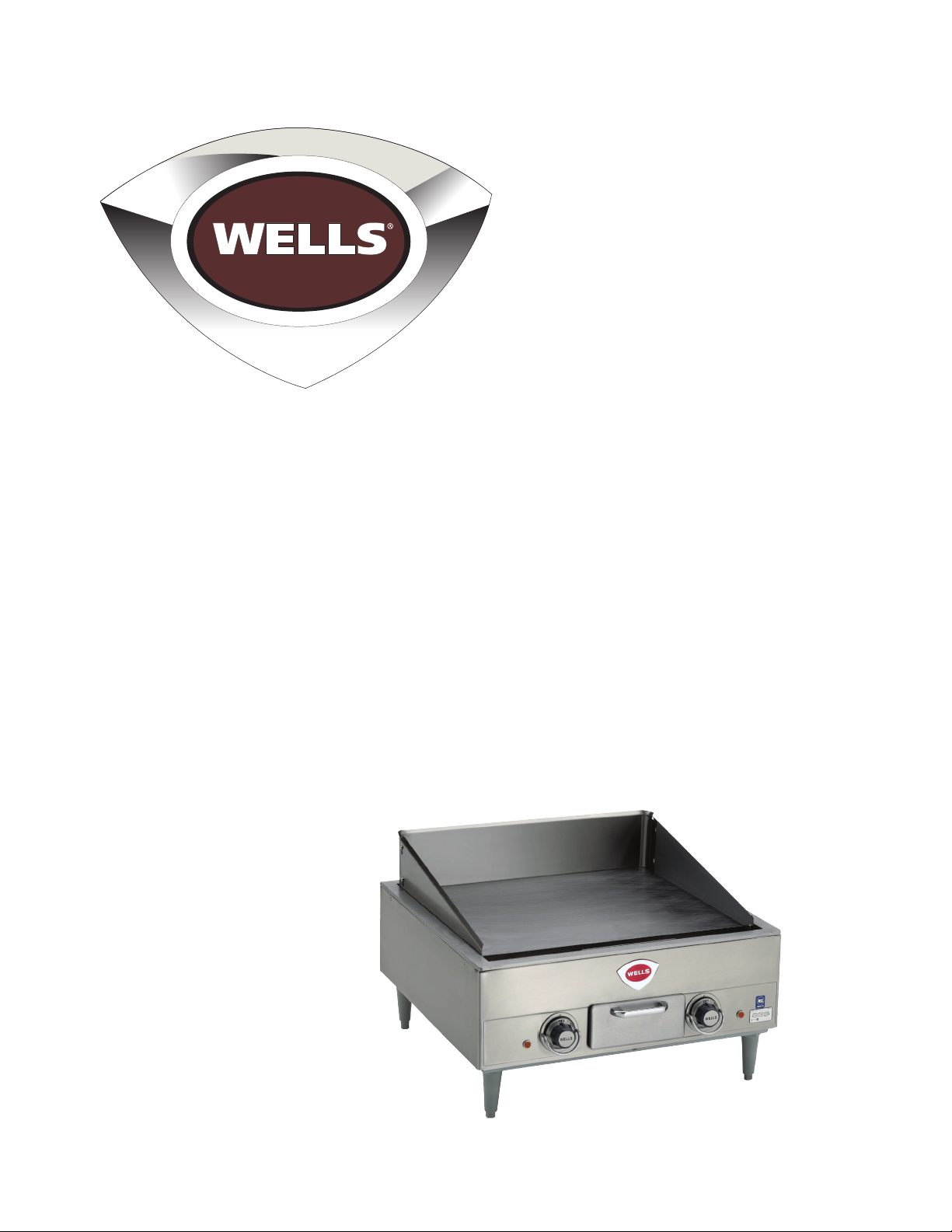
Electric Countertop Griddle
Owner’s Manual
Models
standard—G13, G19, G23, G24, and G60
grooved—GG13, GG19, GG23, GG24, and GG60
chrome plated—PG13, PG19, PG23, PG24, and PG60
This manual includes material related to installation,
use , cleaning, and care. Exploded view[s], as well
as any available parts list[s] and wiring diagram[s]
pertaining to the unit[s] covered by this manual are
also included.
This manual must be read and understood by all
persons using or installing this appliance. Contact
your Wells dealer if you have any questions concerning
installation, use, or maintenance of this equipment.
DO NOT DISCARD THIS MANUAL.
G13
2M-303339 • Rev. H • 04.2017
Page 2

LIMITED WARRANTY STATEMENT
Unless otherwise specifi ed, all commercial cooking equipment manufactured by Wells Manufacturing
is warrantied against defects in materials and workmanship for a period of one year from the date of
original installation or 18 months from the date of shipment from our factory, whichever comes fi rst,
and is for the benefi t of the original purchaser only. This warranty is the complete and only warranty,
expressed or implied in law, or in fact, including but not limited to, warranties of merchantability or
fi tness for any particular purpose, and/or for direct, indirect, or consequential damages in connection
with Wells products. This warranty is void if it is determined that, upon inspection by an authorized
service agency, the equipment has been modifi ed, misused, misapplied, improperly installed, or
damaged in transit or by fi re, fl ood or act of God. It also does not apply if the serial nameplate has
been removed, or if service is performed by unauthorized personnel. The prices charged by Wells
Manufacturing for its products are based upon the limitations in this warranty. Seller’s obligation
under this warranty is limited to the repair of defects without charge by a Wells Manufacturing
factory authorized service agency or one of its sub-service agencies. This service will be provided
on customer’s premises for non-portable models. Portable models [see list of portable models below]
must be taken or shipped to the closest authorized service agency, transportation charges prepaid,
for service. In addition to restrictions contained in this warranty, specifi c limitations are shown in the
Service Policy and Procedure Guide. Wells Manufacturing authorized service agencies are located
in principal cities. This warranty is valid in the United States and Canada and void elsewhere. Please
consult your telephone directory, your foodservice equipment dealer, or contact Wells Manufacturing
directly for information and other details concerning warranty.
PARTS WARRANTY
All genuine Wells replacement parts are warrantied for ninety [90] days from date of purchase on
non-warranty equipment. This parts warranty is limited only to replacement of the defective part[s].
Any use of non-genuine Wells parts completely voids any warranty.
SERVICES AND EXPENSES NOT COVERED BY WARRANTY
• Travel time and mileage rendered beyond the 50-mile • Voltage conversions or gas conversions
radius limit • Pilot light adjustment
• Mileage and travel time on “portable” equipment • Miscellaneous adjustments
[see below] • Thermostat calibration and bypass adjustment
• Labor to replace such items that can be replaced easily • Resetting of circuit breakers, safety controls,
during a daily cleaning routine [e.g., removable kettles or reset buttons
on fryers, knobs, grease drawers on griddles, etc.] • Installation of equipment
• Replacement of normal wear items such as bulbs, • Cleaning of equipment
fuses, etc. • Seasoning of griddle plates
• Charges incurred by delays, waiting time, or operating • Repair of damage created during transit, delivery,
restriction that hinder the service technician’s ability or installation or created by an act of God
to perform service. Any overtime premium will be • All labor must be performed during regular working
charged to the buyer. hours.
PORTABLE EQUIPMENT
Wells will not honor service bills that include travel time and mileage charges for servicing any products
considered “portable” in nature. These products should be taken to the service agency for repair.
The foregoing warranty is in lieu of any and all other warranties expressed or implied and constitutes
the entire warranty.
Should you require any assistance regarding the operation or Business hours: 8:00 a.m. to 4:30 p.m.
maintenance of any Wells equipment; write, phone, fax or email Central Standard Time
our Service Department. In all correspondence mention the Telephone: 314.678.6314 Fax: 314.781.2714
model number and the serial number of your unit, as well as Email: [email protected]
the voltage or type of gas you are using. Website: www.wellsbloomfi eld.com
i
Page 3

TABLE OF CONTENTS
Warranty i
Warnings, General Information and Installation 1–3
Electrical Figures/Wiring 4
Wiring Diagrams 5–9
Daily Operation and Cleaning 10–11
Troubleshooting 11
Parts List 12–21
Exploded Views 22–31
2M-303339 Rev H Owner’s Manual for Wells Countertop Electric Griddles
Page 4

NOTES
CUSTOMER SERVICE DATA
Please have this information available if calling customer service at any point.
Restaurant Location
Technician Installation Date
Service Company
Street Address State Zip Code
Email Phone Number
Model Number Serial Number
Voltage/Phase
iii
Page 5

SAFETY SYMBOLS
with this unit.
These symbols are intended to alert the user to the
presence of important operating and maintenance
instructions in the manual accompanying the appliance.
THOROUGHLY INSPECT YOUR UNIT ON ARRIVAL
This unit has been tested for proper operation before leaving our plant to ensure delivery of your unit
in perfect condition. However, there are instances in which the unit may be damaged in transit. In the
event you discover any type of damage to your product upon receipt, you must immediately contact
the transportation company who delivered the item to you and initiate your claim with that company.
If this procedure is not followed, it may a ect the warranty status of the unit. If damage or loss is not
apparent until after equipment is unpacked, a request for inspection of concealed damage must be
made with carrier within 15 days. Please record the model number, serial number, voltage, and purchase
date in the area below at the time of receipt..
Model Number
Serial Number
Voltage
Purchase Date
MAINTENANCE AND REPAIRS
Contact your local authorized service agent for service or required maintenance. Please have the
information in the above fi elds ready when you call to ensure a faster service.
Using any part other than genuine Wells factory supplied parts relieves the manufacturer of all liability.
Due to periodic changes in designs, methods, procedures, policies, and regulations, the specifi cations
contained in this document are subject to change without notice. Wells reserves the right to change
product specifi cations and design without notice. In regards to previously purchased equipment,
such revisions do not entitle the buyer to corresponding changes, improvements, additions or
replacements. While Wells Manufacturing exercises good faith e orts to provide information that
is accurate, we are not responsible for errors or omissions in information provided or conclusions
reached as a result of using the specifi cations. By using the information provided, the user assumes
all risks in connection with such use. When performing maintenance, power to the unit should be
unplugged or turned o .
PLEASE REFER TO THE WARRANTY PAGE FOR SPECIFIC WARRANTY INFORMATION.
AUTHORIZED SERVICE AGENT LISTING
Reference the listing provided with the unit or for an updated listing go to the website or call customer
service to fi nd an agent.
Business hours: 8:00 a.m. to 4:30 p.m. Central Standard Time
Telephone: 314-678-6303
Fax: 314-781-2714
Email: [email protected]
Website: www.wellsbloomfi eld.com
Please visit www.starwebconnect.com/manuals.aspx for digital versions of any documents associated
2M-Z21001 Rev- Owner's Manual for IRCS4 Impingement/Radiant Split-Belt Conveyor Toaster
1
2M-303339 Rev H Owner’s Manual for Wells Countertop Electric Griddles
Page 6
CERTIFICATIONS
These units conforms to NSF standard 4 for sanitation, but only if installed in accordance
with the supplied installation instructions and maintained according to the instructions
in this manual. 208 V, 240 V, and 480 V versions of these units are “U” listed under UL file
E6070. 380–415 V versions of the G13, G19, G23, and G24 griddles [as well as the same
models preceded by a “P” or “G”] are CSA and CE certified.
CAUTION
Do not connect this appliance to power until all installation instructions are read,
understood, and followed. Damage to the unit, the counter, or users may result
if these instructions are not followed completely.
All servicing requiring access to non-insulated electrical components must be
performed by a factory authorized technician. Do not open any access panel
which requires the use of tools. Failure to follow this warning may result in severe
electrical shock.
Exposed surfaces can be hot to the touch and may cause burns. Contact with
the cooking surface can and will cause sever burns. Always wear protective
clothing and never make direct contact to the griddle surface.
Avoid storing flammable or combustible materials in, on, or near the unit.
Electrical installation other than as specified will void the UL certification listing
and may void the warranty. The ground lug of this appliance must be connected
to a suitable building ground.
Cleanliness of this unit is essential to good sanitation. Read and follow all
included cleaning instructions and schedules to ensure the safety of the
food product.
Do not submerge this unit in water. Do not direct water jet or steam jet at this
unit or at the controls or wiring. Do not splash or pour water on, in, or over any
controls, control panel, or wiring.
Do not stand or climb on the griddle. Any cracks in the unit due to standing
or climbing on the griddle will not be covered under warranty.
GENERAL SAFETY INFORMATION
This equipment is designed and sold for commercial use only, and is intended for use by personnel
trained and experienced in its operation. This is not sold for consumer use in and around the home
nor for use directly by the general public in food service locations.
Before using your new equipment, read and understand all the instructions and labels associated
with the unit prior to putting it into operation. Make sure all people associated with its use understand
the units operation and safety before they use the unit.
2
Page 7
GENERAL INSTALLATION INFORMATION
The unit is shipped fully assembled with the exception of the legs and splash guard which will need
to be installed during the unpacking process. The legs will thread into the holes on each end of the
chassis [as well as in the middle on G60 models] and once set in place, the splash guard locks over
the studs in the grease trough to secure it in place. It is shipped ready to hardwire to an electrical
connection adequate for its voltage and amp draw. If improper electrical supply can be determined
through troubleshooting, contact a qualified electrician prior to using the unit. Should you require
assistance, contact your local authorized service agent for any service or required maintenance.
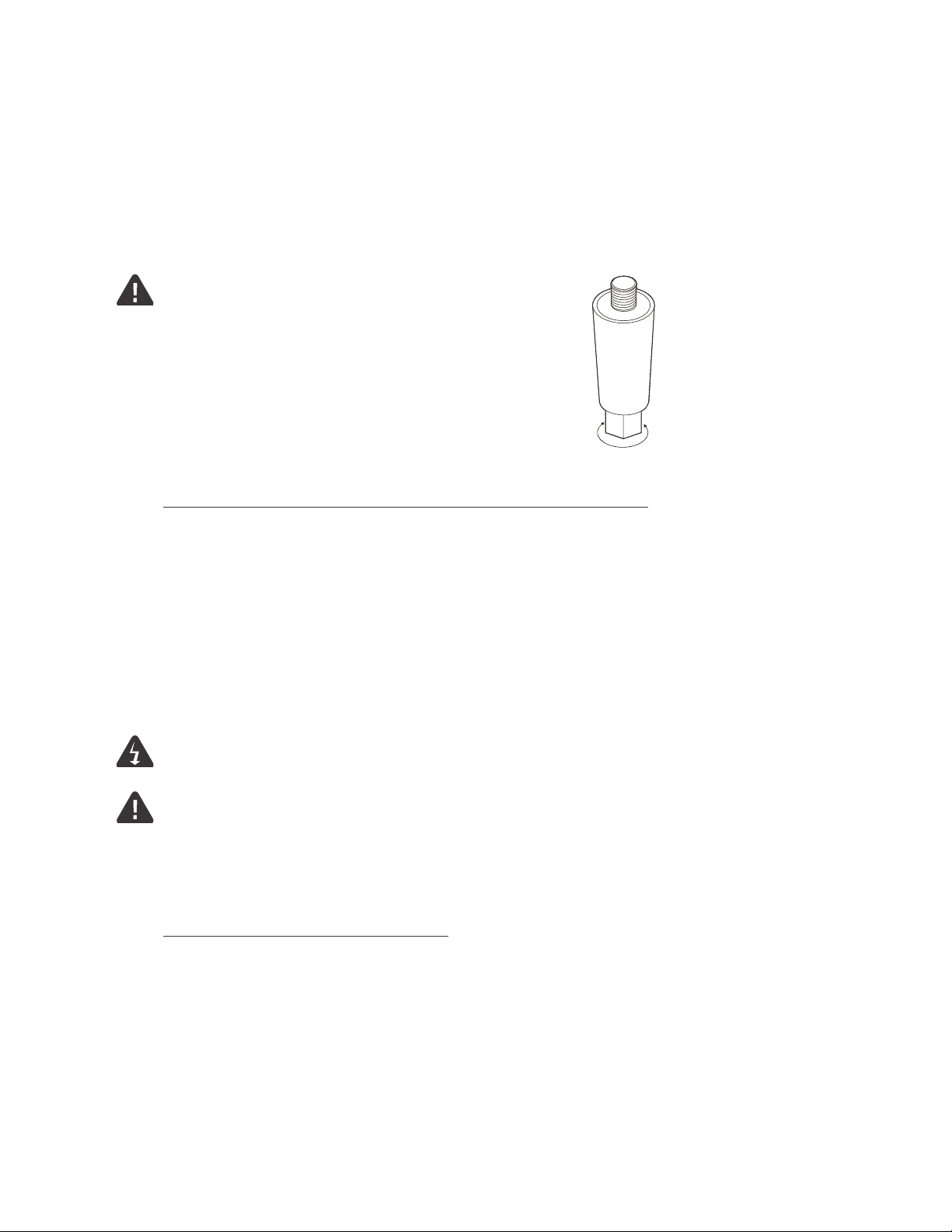
Set the unit so that the rear is 0.25 inches (6 mm) higher
than the front using the adjustable feet. Make certain the
griddle has at least the minimum clearance on the sides
and back as called out on the nameplate of the unit. The
installation must be on a non-combustible surface such
as concrete, tile, terrazo, or metal [solid not metal covered].
Before using the unit for the first time, make sure to clean
turn to adjust height
the unit properly. Refer to the “Daily Operation” section
for cleaning instructions.
Remember, the installation must meet all federal, local, and NFPA codes.
VENTILATION
Make certain not to obstruct the flow of combustion and ventilation air. Provisions for adequate
air supply must be furnished. The legs supplied with the unit must be installed. Make certain that
air intake openings in the bottom of the appliance are not obstructed, as they are essential for
proper combustion and operation of the appliance.
It is essential that some form of exhaust hood be provided over the griddle to carry o fumes
and gases. The unit should never be directly connected to a flue or stack.
ELECTRICAL CONNECTION
DO NOT CONNECT OR ENERGIZE THIS UNIT UNTIL ALL INSTRUCTIONS ARE READ, UNDERSTOOD,
AND FOLLOWED.
For your protection we recommend that a qualified electrician work on connecting this griddle.
They should be familiar with electrical installations and all electric codes. Proper connections and
power supply are essential for ecient performance. The external wiring should be in conduit
or an approved type of flexible cable suitable for operation at the temperature indicated on the
wiring diagram for your unit, and of a proper size to carry the load. The supply circuit should be
properly fused and equipped with a means of disconnecting, as required by local electrical code.
The body of the griddle must be grounded.
Before making any electrical connection to this unit, check that the power supply is adequate for the
voltage, amperage, and requirements stated on the nameplate. This unit will be shipped ready to hard
wire. Make certain to disconnect the unit from the power source before installing or removing any parts.
Be absolutely sure that the ground connection for the receptacle is properly wired. Do not connect
equipment to power without proper ground connections. Improper grounding may result in personal
injury or fatality. Damage due to connecting the unit to power incorrectly is not covered by warranty.
3
2M-Z21001 Rev- Owner's Manual for IRCS4 Impingement/Radiant Split-Belt Conveyor Toaster
2M-303339 Rev H Owner’s Manual for Wells Countertop Electric Griddles
Page 8
ELECTRICAL FIGURES
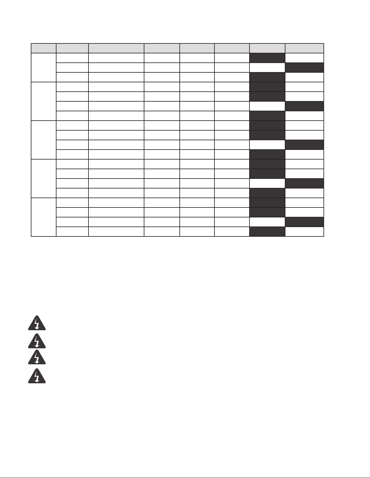
MODEL VOLTAGE TOTAL kW L1 L2 L3 N [wye] 1-phase
208/240 6.8/9 14/18.7 28.1/32.5 14/18.7 32.5/37.5
G13
G19
G23
G24
G601
1This unit has two connections—amps are shown per connection [half of total for unit].
380–415 10.7 [max] 14.8 [max] 14.8 [max] 14.8 [max] 0
480 9 9.4 16.2 9.4 18.7
208 12 28.8 49.9 28.8 57.6
240 12 25 43.3 25 50
380–415 16.1 [max] 22.2 [max] 22.2 [max] 22.2 [max] 0
480 12 12.5 21.6 12.5 25
208 15.9 48.3 51.3 35 76.9
240 16 41.7 44.4 30.4 66.6
380–415 16 [max] 15.8 [max] 31.6 [max] 19.1 [max] 14.5 [max]
480 16 20.9 22.2 15.2 33.3
208 20.9 63.4 67.1 45.8 103.3
240 21 55 58.3 39.6 89.5
380–415 21 [max] 20.9 [max] 41.8 [max] 25 [max] 19.1 [max]
480 21 27.1 28.9 19.9 43.8
208 31.8 [2 x 15.9] 48.31 51.31 351 76.91
240 32 [2 x 16] 41.71 44.41 30.41 66.61
380–415 32.4 [max, 2 x 16.2] 15.81 [max] 31.61 [max] 19.11 [max] 28.3 [max]
480 32 [2 x 16] 20.91 221 15.21 33.31
WIRING
208 V, 208 V/240 V, 240V, and 480 V models may be wired for operation in the field for either 1-phase
or 3-phase [delta] power supplies by making line connections at the junction box located at the right,
rear of the unit as described on the wiring diagram. G60 models will have an additional box on the left
rear as it utilizes two connections. 380 V–415 V models can only be wired as 3-phase wye.
CONNECT/PLUG UNIT INTO DEDICATED AC LINE WITH APPROPRIATE
AMPERAGE/VOLTAGE AS SPECIFIED ON THE NAMEPLATE OF THE UNIT.
DO NOT IMMERSE OR LET THE UNIT STAND IN WATER.
DO NOT HOSE DOWN THE UNIT OR THE TABLE/COUNTER IF THE UNIT
IS ON THE TABLE/COUNTER.
KEEP AWAY FROM RUNNING WATER.
4
Page 9
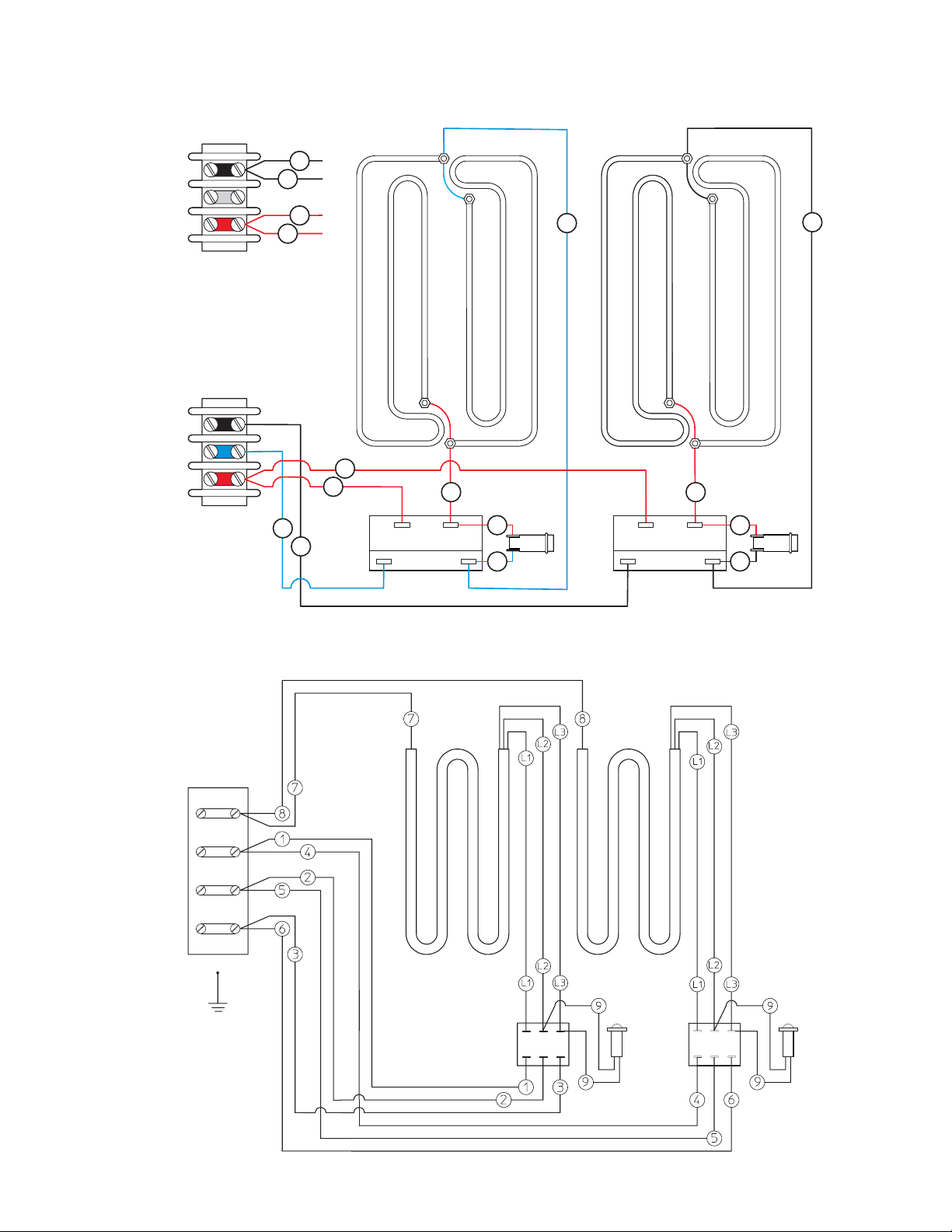
WIRING DIAGRAMS
G13
208 V, 240 V, 480 V
L1
L2
single phase
L1
L3
L2
three phase
[delta]
6
5
2
1
2
1
5
6
thermostat
3
99
1010
thermostat
1111
4
G13
380 V–415 V
three phase
[wye]
N
L3
L2
L1
thermostatthermostat
2M-Z21001 Rev- Owner's Manual for IRCS4 Impingement/Radiant Split-Belt Conveyor Toaster
5
2M-303339 Rev H Owner’s Manual for Wells Countertop Electric Griddles
Page 10
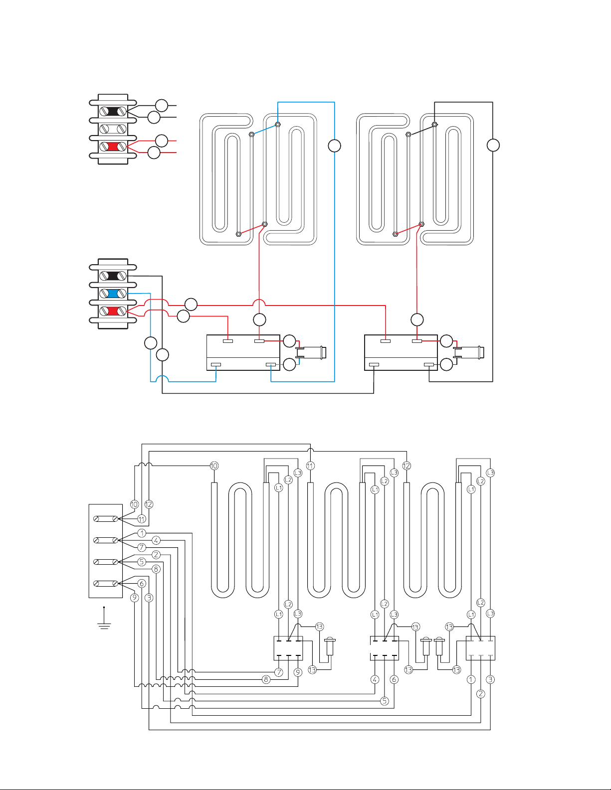
WIRING DIAGRAMS
G19
208 V, 240 V, 480 V
L1
L2
single phase
L1
L3
L2
three phase
[delta]
6
5
2
1
2
1
5
6
thermostat
3
99
1010
thermostat
1111
4
G19
380 V–415 V
three phase
[wye]
N
L1
L2
L3
thermostat thermostatthermostat
6
Page 11
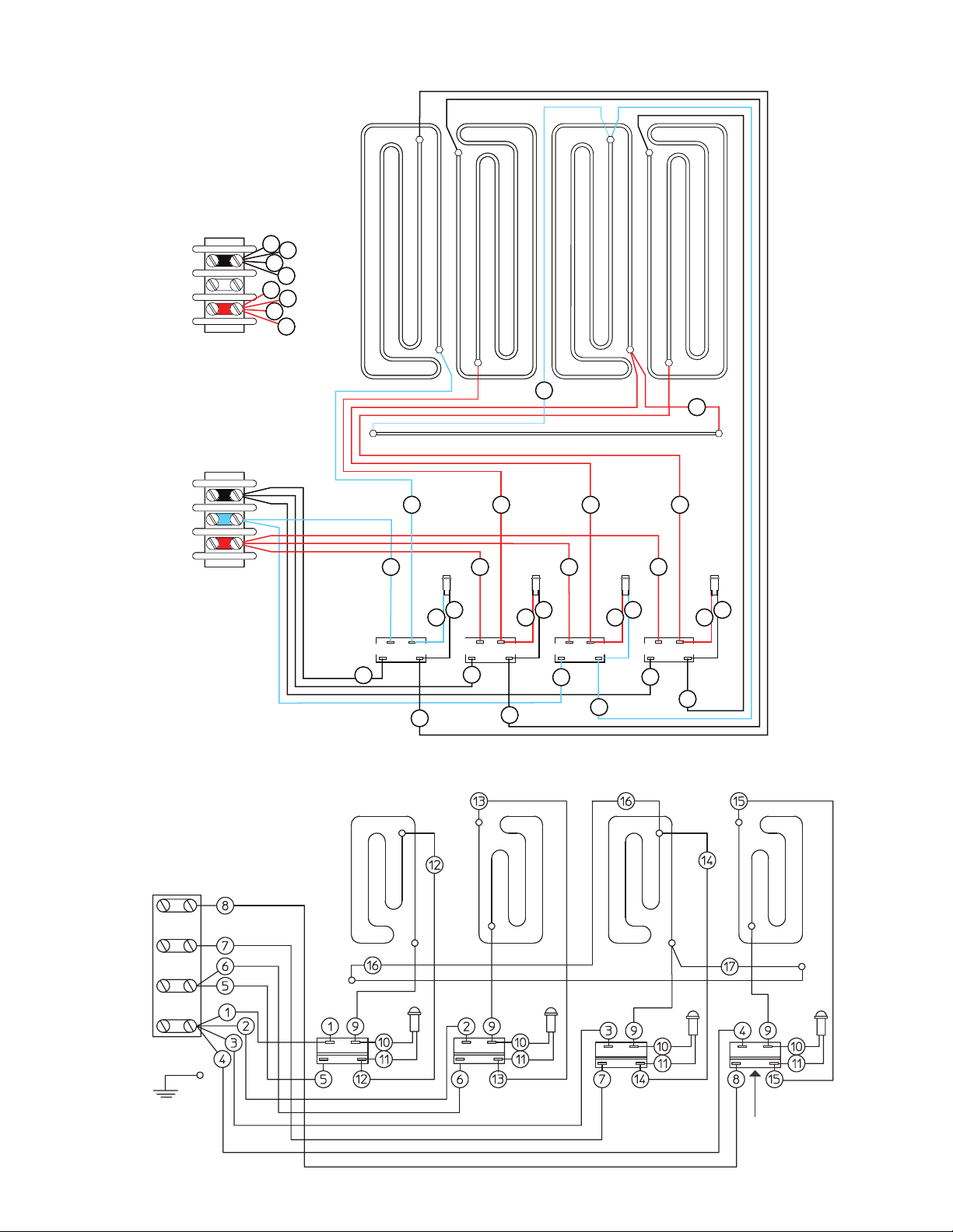
WIRING DIAGRAMS
5
6
7
8
1
2
3
4
16
9
1 2 3 4
11
15
8
14
13
12
7
6
5
10
11
10
11
10
11
10
9
9
9
17
G23
208 V, 240 V, 480 V
5
L1
L2
single phase
1
6
7
8
2
3
4
L1
L3
L2
G23
380 V–415 V
three phase
[delta]
9
1 2 3 4
thermostat thermostat thermostat thermostat
5
11
10
12
perimeter element
9
10
6
13
16
9
11
7
11
10
14
17
9
11
10
8
15
three phase
[wye]
N
L1
L2
L3
perimeter
element
thermostat [1 of 4]
7
2M-Z21001 Rev- Owner's Manual for IRCS4 Impingement/Radiant Split-Belt Conveyor Toaster
2M-303339 Rev H Owner’s Manual for Wells Countertop Electric Griddles
Page 12
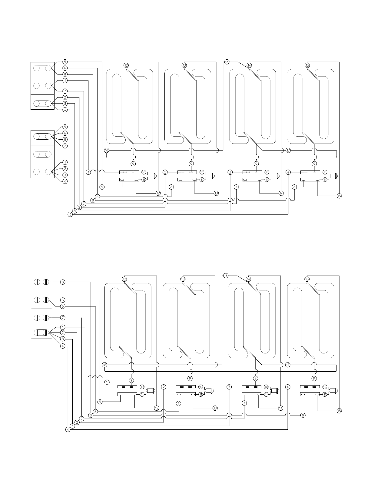
WIRING DIAGRAMS
G24
208 V, 240 V, 480 V
L1
L2
single phase
L1
L3
L2
three phase
[delta]
G24
380 V–415 V
N
L3
L2
perimeter
element
thermostat thermostat thermostatthermostat
L1
three phase
[wye]
8
perimeter
element
thermostatthermostatthermostatthermostat
Page 13

WIRING DIAGRAMS
5
6
7
8
1
2
3
4
16
9
1 2 3 4
11
15
8
14
13
12
7
6
5
10
11
10
11
10
11
10
9
9
9
17
G60 [1 of 2, this unit uses this diagram twice, once
for the left half and once for the right half]
208 V, 240 V, 480 V
L1
L2
single phase
L1
L3
L2
three phase
[delta]
5
6
7
8
1
2
3
4
9
1 2 3 4
11
10
thermostat thermostat thermostat thermostat
5
12
perimeter element
9
10
6
13
16
17
9
11
7
11
10
14
9
11
10
8
15
G60 [1 of 2, this unit uses this diagram twice, once
for the left half and once for the right half]
380 V–415 V
three phase
[wye]
N
L1
L2
L3
perimeter
element
thermostat
[1 of 4, per side]
9
2M-Z21001 Rev- Owner's Manual for IRCS4 Impingement/Radiant Split-Belt Conveyor Toaster
2M-303339 Rev H Owner’s Manual for Wells Countertop Electric Griddles
Page 14

DAILY OPERATION
THE GRIDDLE SURFACE AND SURROUNDING AREAS
CAN AND WILL BE VERY HOT DURING AND AFTER
OPERATION. AVOID DIRECT CONTACT WITH HOT
SURFACES AS THEY ARE A BURN HAZARD.
DO NOT SUBMERGE OR SPRAY DOWN GRIDDLE.
WATER SHOULD BE USED SPARINGLY AND ONLY
AS INSTRUCTED WHEN CLEANING. DAMAGE FROM
EXPOSURE TO WATER WILL NOT BE COVERED
BY WARRANTY AND MAY PRESENT AN ELECTRICAL
HAZARD.
DO NOT USE DETERGENT OR OVEN CLEANER TO
CLEAN THE GRIDDLE SURFACE.
GRIDDLE CARE
It takes very little time and e ort to keep the griddle
attractive and performing at top eciency. If grease
is permitted to accumulate, it forms a viscous residue
and then carbonizes, making it extremely dicult to
remove. To prevent this condition, the following
suggestions for cleanliness should be followed.
SUGGESTED CLEANING TOOLS
STANDARD STEEL/GROOVED SURFACE
griddle brick or pumice stone, soft bristle fiber brush,
plastic scouring pad, plastic or razor scraper [contoured
scraper for grooved surface models], mild detergent,
non-abrasive cleaner, and clean, soft cloth or sponge
CHROME SURFACE
razor-sharp scraper, soft bristle fiber brush, mild
detergent, non-abrasive cleaner, and clean, soft cloth
or sponge
CLEANING
To begin the cleaning process, set the thermostats to
approximately 225° F (107° C) and allow enough time
for the griddle to reach this temperature. Before
starting, pour a very small amount of water on the
griddle plate and let is sizzle. Be careful not to use
too much water, which can create excessive steam.
i. STANDARD STEEL/GROOVED SURFACE
After each use, scrape the griddle with a scraper
or flexible spatula to remove excess grease and food
and maneuver it into the grease chute. Use a soft bristle
brush in a circular motion to remove any remaining food
particles. If there is an accumulation of burned on
grease and/or food, the griddle should be thoroughly
scoured and re-seasoned.
Use pumice or griddle stone while the griddle is warm.
Do not use steel wool because of the danger of steel
slivers getting into the food. Follow this by turning the
unit o and after it has cooled, wipe it with a clean
damp cloth with no cleaner.
CHROME-- SURFACE
After each use, scrape the griddle with a razor-sharp
scraper. Use a soft bristle brush in a circular motion
to remove any remaining food particles. Follow this
by turning the unit o and after it has cooled, use
a soft, damp cloth and a non-silicate, non-abrasive,
non-chlorinated cleaner to wipe the surface clean.
Wipe it with a clean damp cloth with no cleaner. ON
CHROME SURFACES, NEVER USE PUMICE, GRIDDLE
STONES, ABRASIVES, STEEL WOOL, COMMERCIAL
LIQUID GRILL CLEANER, AND NEVER STRIKE THE
GRIDDLE SURFACE WITH A SHARP AND/OR HARD
INSTRUMENT.
ii. Daily use of a clean cloth and a good non-abrasive
cleaner to clean the stainless steel body of the
griddle is recommended. Wipe the polished front
with a soft cloth so not to scratch the finish.
iii. At least once a day, remove the grease drawer and
wash it using the same process as an ordinary cooking
utensil. The drawer is removed by pulling forward until
it is released from its track. The splash guard should
also be removed and cleaned in a similar manner.
SEASONING THE GRIDDLE HEATING SURFACE
After the griddle has been thoroughly cleaned, it should
be seasoned to prevent food from sticking. Before using
and after each thorough scouring, season the griddle
heating surface in the following manner. CHROME
GRIDDLES DO NOT REQUIRE SEASONING.
i. Turn the temperature control dials to 350°F (177°C).
ii. Using a clean cloth, not a spatula, spread a thin film
of cooking oil over the griddle cooking surface. This
film should remain on the hot griddle surface for half
an hour.
iii. Remove the excess oil and wipe clean.
iv. Apply another film of cooking oil over the hot cooking
area for another half hour and again remove excess
oil and wipe clean. The griddle surface should now
be ready for use.
10
Page 15
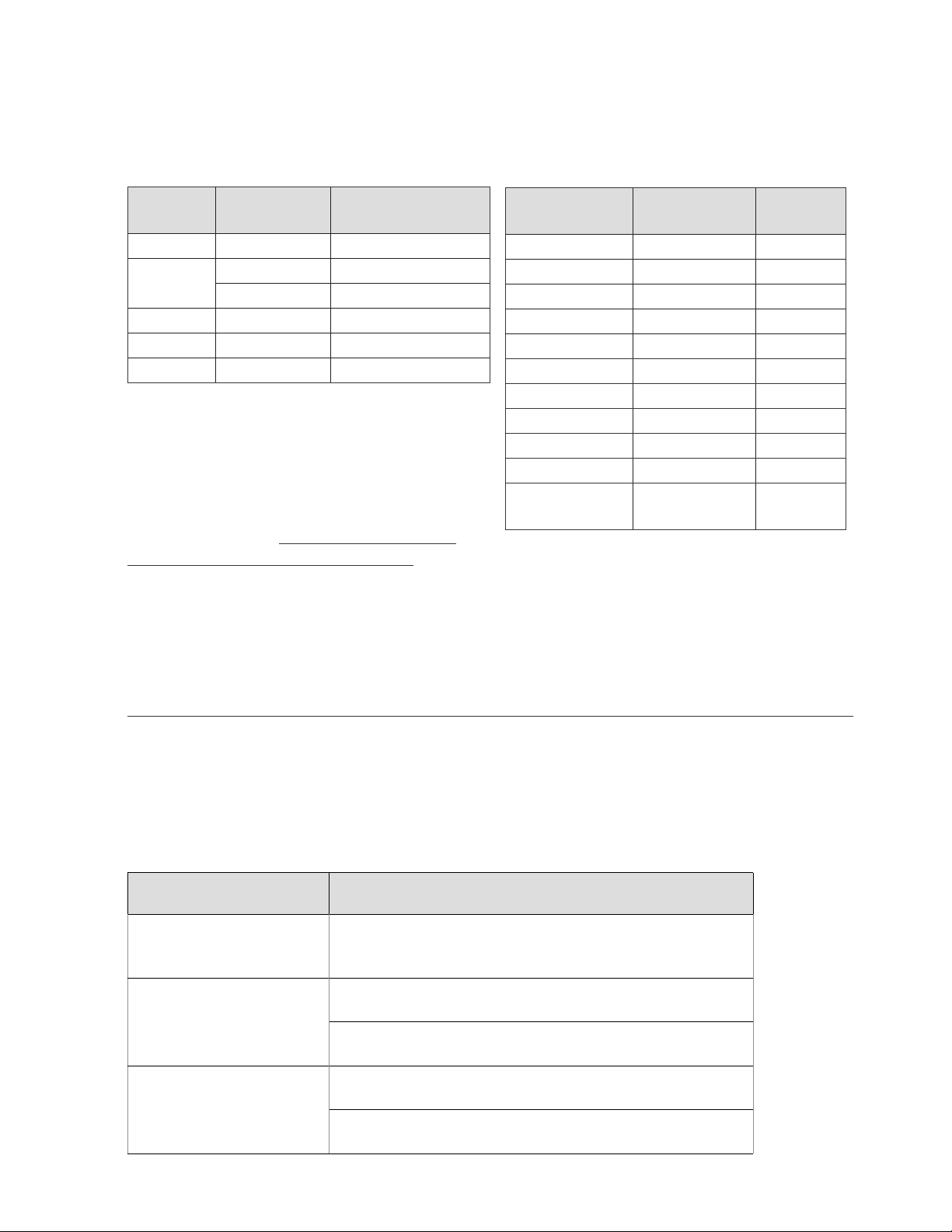
TEMPERATURE CONTROL
To power on the elements, turn the adjustment knob
to the desired temperature. Turning the dial knob
automatically maintains the selected heat range.
RECOMMENDED GRILLING TIMES AND TEMPERATURES
These times are meant as suggestions only. Your own
experience with your menu items will always be the
best resource when determining proper cook times.
Model
Listed
Voltage
Number of
Control Knobs
G13 all 2
G19
208, 240, 480 2
380–415 3
G23 all 4
G24 all 4
G60 all 8
COOKING
Set each section’s thermostat knob at the desired
temperature. After a short pre-heating period, the
indicator light will turn o until there is a change
in temperature, including when product is added,
and the thermostat will automatically maintain the
selected temperature. On chrome surfaces, wipe
grease into grease trough after each order.
Product Temperature
Time
in Minutes
bacon 350° F (177° C) 2–3
beef tenderloin 400° F (204° C) 3–4
broiled ham 375° F (191° C) 2
canadian bacon 350° F (177° C) 2–3
hamburger 350° F (177° C) 3–4
club steak 400° F (204° C) 3–5
ham steak 375° F (191° C) 3–4
hot dog 325° F (163° C) 2–3
grilled cheese 375° F (191° C) 3–4
minute steak 400° F (204° C) 3–4
sausage
[link or patty]
350° F (177° C) 3
IDLING
During idle periods, to save on operating costs, lower
the temperature setting of the thermostat to about
250°F (121°C). It is not necessary to maintain cooking
temperature during idle periods, as the griddle can
quickly be reheated to the desired temperature.
TROUBLESHOOTING
If the unit does not initially power on, make certain the unit is wired properly and
that the power supply is the correct voltage and amperage to support operation
of the unit. In any and all cases of damage or malfunction, this griddle should be
serviced by authorized Wells service agents only and not by the user.
SYMPTOM POSSIBLE CAUSES/TROUBLESHOOTING
Unit is not receiving proper power. Circuit breaker o
Entire griddle will not heat.
One section of the Griddle
will not heat.
Griddle drips grease
or tripped. If resetting breaker does not fix the issue, contact
a certified electrician to examine the wiring.
The thermostat may be set incorrectly on that section.
Check its position first to ensure it is set correctly.
If the setting is correct, there may be a damaged internal
component. Contact an authorized Wells service agent.
Check the grease drawer to make certain it is not overflowing
and is installed in the unit.
If the grease drawer is not causing the issue, there may be
a damaged component. Contact an authorized Wells service agent.
2M-Z21001 Rev- Owner's Manual for IRCS4 Impingement/Radiant Split-Belt Conveyor Toaster
11
2M-303339 Rev H Owner’s Manual for Wells Countertop Electric Griddles
Page 16
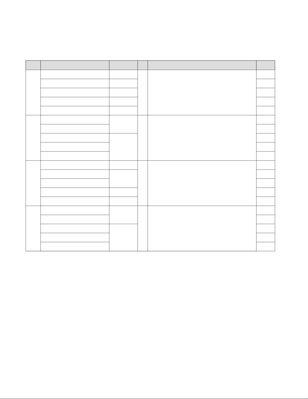
PARTS LIST
Items labeled “NP” are not pictured/represented.
380 V–415 V models are referred to as 400 V for reference.
REF NO MODEL PART NUMBER QTY DESCRIPTION PAGE NO
G13, GG13, PG13 [all] 5G-20632
G19, GG19, PG19 [all] 5G-20634
1
G23, GG23, PG23 [all] 5G-20635
1 splash guard assembly [includes 1a, 1b, and 1c]
G24, GG24, PG24 [all] 5G-20636
G60, GG60, PG60 [all] 5G-20637
G13, GG13, PG13 [all]
22
24
26
28
30
22
G7-35781
G19, GG19, PG19 [all]
1a
G23, GG23, PG23 [all]
G24, GG24, PG24 [all]
G7-35783
1 left splash guard
G60, GG60, PG60 [all]
G13, GG13, PG13 [all] G7-34437
G19, GG19, PG19 [all]
24
26
28
30
22
24
G7-34436
1b
G23, GG23, PG23 [all]
1 rear splash guard
G24, GG24, PG24 [all] G7-34439
G60, GG60, PG60 [all] G7-34440
G13, GG13, PG13 [all]
26
28
30
22
G7-35780
G19, GG19, PG19 [all]
24
1c
G23, GG23, PG23 [all]
G24, GG24, PG24 [all]
G7-35782
1 right splash guard
G60, GG60, PG60 [all]
26
28
30
12
Page 17
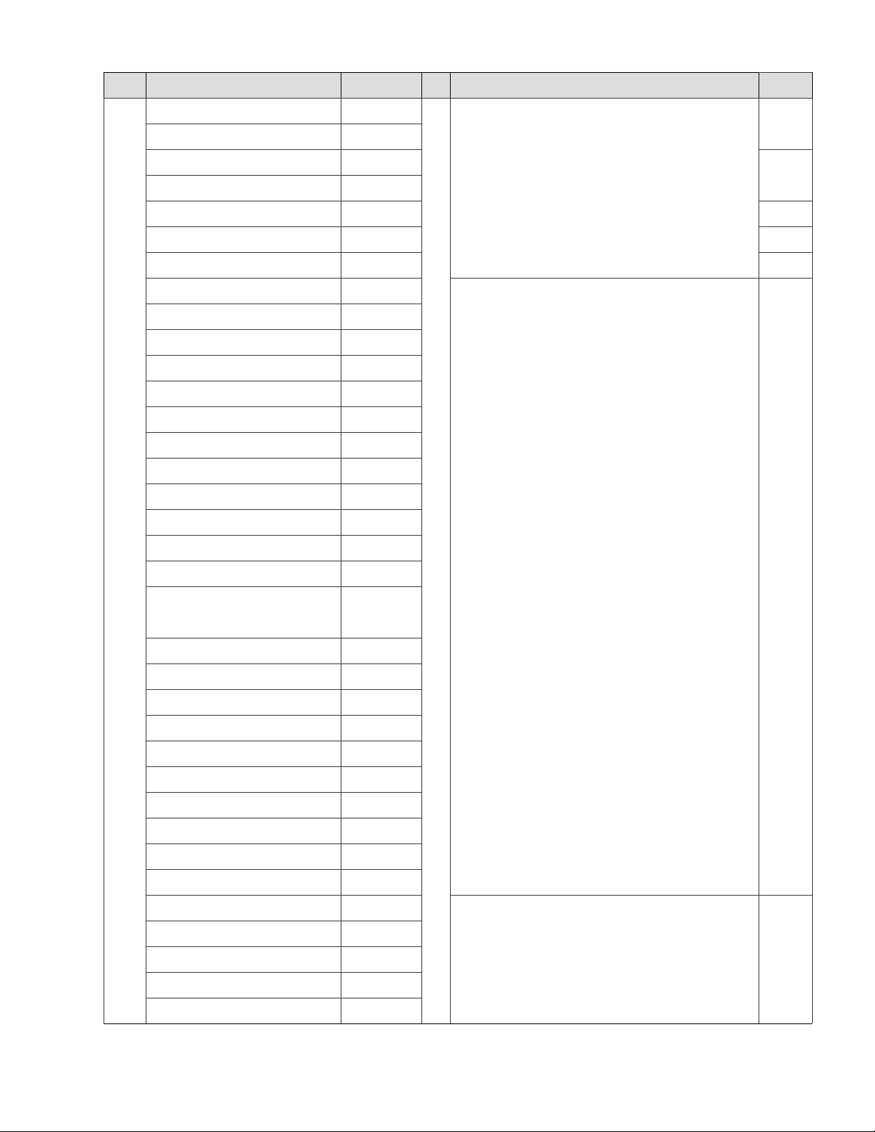
REF NO MODEL PART NUMBER QTY DESCRIPTION PAGE NO
G13 [208 V/240 V], G13-480V 2F-302451
G13-400 2F-302745
G19-208, G19-240, G19-480V 2F-302452
G19-400 2F-302559
G23 [all] 2F-302453
G24 [all] 2F-302454
G60 [all] 2F-302455
GG13L1 [208 V/240 V] 2F-Z20032
GG13L2 [208 V/240 V] 2F-304120
GG13-FGR [208 V/240 V] 2F-302451A
GG13R1 [208 V/240 V] 2F-302451B
GG19L2-240V 2F-Z13714
GG19L3-400V 2F-Z17042
GG19C2-208V 2F-Z14396
GG19R3-208V 2F-Z14546
GG19R2-208V 2F-Z16220
GG23L1-208V 2F-Z13307
22
24
standard griddle plate assembly
26
28
30
2
GG23L2-208V 2F-Z13336
GG23L3-208V, GG23L3-240V 2F-Z15118
GG23FGR-208V, GG23FGR-240V, GG23-
400, GG23-480V
GG23R3-480V
GG23R2 [all] 2F-Z13406
GG24L2-208V 2F-Z12823
GG24L3-208V 2F-Z16165
GG24L4-208V 2F-Z18123
GG24FGR-208V, GG24FGR-480V 2F-Z13351
GG24-400 2F-306328
GG60L3-208 2F-Z16241
GG60L5-208V 2F-Z13187
GG60FGR-208V 2F-Z13352
PG13 [all] 2F-302529
PG19 [208 V, 240 V, and 480 V] 2F-302530
PG23 [all] 2F-302531
2F-302453A
2F-Z16550
1
grooved griddle plate assembly
chrome-plated griddle plate assembly
NP
NP
PG24 [all] 2F-302532
PG60 [all] 2F-302533
13
2M-Z21001 Rev- Owner's Manual for IRCS4 Impingement/Radiant Split-Belt Conveyor Toaster
2M-303339 Rev H Owner’s Manual for Wells Countertop Electric Griddles
Page 18
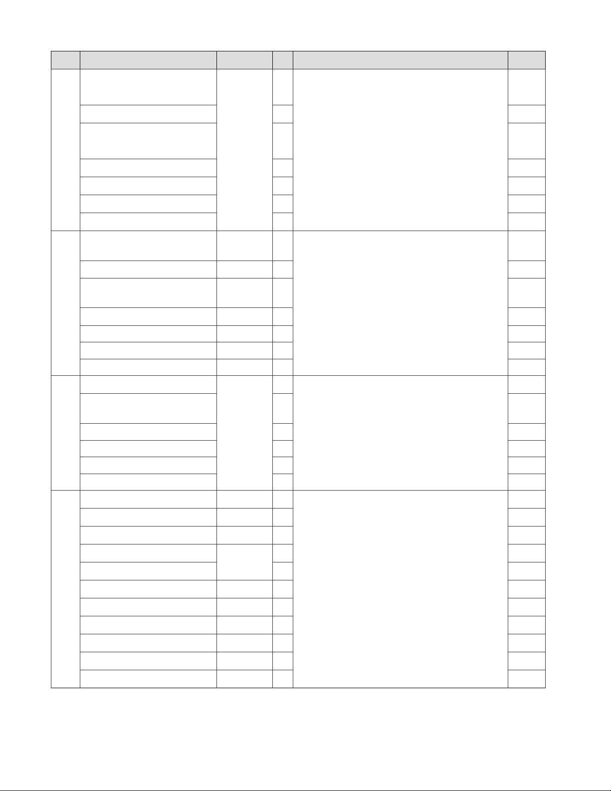
REF NO MODEL PART NUMBER QTY DESCRIPTION PAGE NO
G13, GG13, and PG13
[208 V, 240 V, and 480 V models]
G13, GG13, and PG13 [400 V models] 6
G19, GG19, and PG19
3
[208 V, 240 V, and 480 V models]
G19, GG19, and PG19 [400 V models] 9
G23, GG23, and PG23 [all] 12
G24, GG24, and PG24 [all] 12
G60. GG60, and PG60 [all] 24
G13, GG13, and PG13
[208 V, 240 V, and 480 V models]
G13, GG13, and PG13 [400 V models] 2T-46162 2
G19, GG19, and PG19
4
[208 V, 240 V, and 480 V models]
G19, GG19, and PG19 [400 V models] 2T-46162 3
G23, GG23, and PG23 [all] 2T-30257 4 26
G24, GG24, and PG24 [all] 2T-30257 4 28
G60, GG60, and PG60 [all] 2T-30257 8 30
3
6
1O-32040
sleeving [qty by feet]
2T-30257 2
2T-30257 2 24
thermostat
22
22
24
24
26
28
30
22
NP
NP
G13, GG13, and PG13 [all]
G19, GG19, and PG19
[208 V, 240 V, and 480 V models]
G19, GG19, and PG19 [400 V models] 3 24
5
2A-31974
2
2 24
thermostat shield
G23, GG23, and PG23 [all] 4 26
G24, GG24, and PG24 [all] 4 28
G60, GG60, and PG60 [all] 8 30
G13, GG13, and PG13 [208 V and 240 V] 2J-30516 2
G13, GG13, and PG13 [400 V and 480 V] 2J-Z13363 2 22
G19, GG19, and PG19 [208 V and 240 V] 2J-30516 2 24
G19, GG19, and PG19 [400 V]
3 24
2J-Z13363
G19, GG19, and PG19 [480 V] 2 24
G23, GG23, and PG23 [208 V and 240 V] 2J-30516 4 26
6
pilot light
G23, GG23, and PG23 [400 V and 480 V] 2J-Z13363 4 26
G24, GG24, and PG24 [208 V and 240 V] 2J-30516 4 28
G24, GG24, and PG24 [400 V and 480 V] 2J-Z13363 4 28
G60, GG60, and PG60 [208 V and 240 V] 2J-30516 8 30
22
22
G60, GG60, and PG60 [400 V and 480 V] 2J-Z13363 8 30
14
Page 19
REF NO MODEL PART NUMBER QTY DESCRIPTION PAGE NO
G13, GG13, and PG13 [all]
G19, GG19, and PG19
[208 V, 240 V, and 480 V models]
G19, GG19, and PG19 [400 V models] 3 24
7
D8-30256
2
2 24
knob trim ring
22
G23, GG23, and PG23 [all] 4 26
G24, GG24, and PG24 [all] 4 28
G60. GG60, and PG60 [all] 8 30
G13, GG13, and PG13 [all]
G19, GG19, and PG19
[208 V, 240 V, and 480 V models]
G19, GG19, and PG19 [400 V models] 6 24
8
2C-31718
4
4 24
screw
22
G23, GG23, and PG23 [all] 8 26
G24, GG24, and PG24 [all] 8 28
G60. GG60, and PG60 [all] 16 30
G13, GG13, and PG13
[208 V, 240 V, and 480 V models]
G13, GG13, and PG13 [400 V models] 2R-46164 2
G19, GG19, and PG19
[208 V, 240 V, and 480 V models]
G19, GG19, and PG19 [400 V models] 2R-46164 3
G23, GG23, and PG23
9
[208 V, 240 V, and 480 V models]
G23, GG23, and PG23 [400 V models] 2R-Z17209 4
G24, GG24, and PG24
[208 V, 240 V, and 480 V models]
G24, GG24, and PG24 [400 V models] 2R-Z17209 4
G60, GG60, and PG60
[208 V, 240 V, and 480 V models]
G60, GG60, and PG60 [400 V models] 2R-Z17209 8
2R-30259 2
2R-30259 2
2R-30259 4
knob
2R-30259 4
2R-30259 8
22
22
24
24
26
26
28
28
30
30
10 all 2M-300534 1 Wells emblem
G13, GG13, and PG13 [all] G7-Z12112
G19, GG19, and PG19
[208 V, 240 V, and 480 V models]
G19, GG19, and PG19 [400 V models] G7-Z12097
11
G7-Z12111
1 front panel
G23, GG23, and PG23 [all] G7-Z12109
G24, GG24, and PG24 [all] G7-Z12110
G60. GG60, and PG60 [all] G7-Z13106
22, 24, 26,
28, 30
22
24
NP
26
28
30
15
2M-Z21001 Rev- Owner's Manual for IRCS4 Impingement/Radiant Split-Belt Conveyor Toaster
2M-303339 Rev H Owner’s Manual for Wells Countertop Electric Griddles
Page 20
REF NO MODEL PART NUMBER QTY DESCRIPTION PAGE NO
12
12a
12b
13
G13, GG13, and PG13 [all]
G19, GG19, and PG19 [all]
G23, GG23, and PG23 [all]
WS-50279
G24, GG24, and PG24 [all]
G60. GG60, and PG60 [all] 2
G13, GG13, and PG13 [all]
G19, GG19, and PG19 [all]
G23, GG23, and PG23 [all]
2R-38668
G24, GG24, and PG24 [all]
G60. GG60, and PG60 [all] 2
G13, GG13, and PG13 [all]
G19, GG19, and PG19 [all]
G23, GG23, and PG23 [all]
G7-Z12047
G24, GG24, and PG24 [all]
G60. GG60, and PG60 [all] 2
G13, GG13, and PG13 [all]
G19, GG19, and PG19 [all]
G23, GG23, and PG23 [all]
WS-51989
G24, GG24, and PG24 [all]
G60. GG60, and PG60 [all] 2
22
24
1
grease drawer assembly
26
28
30
22
24
1
grease drawer handle
26
28
30
22
24
1
grease drawer front panel
26
28
30
22
24
1
grease drawer shroud
26
28
30
14 all 2C-33935 15 screw
G13, GG13, and PG13
[208 V, 240 V, and 480 V models]
2A-30586
G13, GG13, and PG13 [400 V models] 2A-Z0314
G19, GG19, and PG19
15
[208 V, 240 V, and 480 V models]
2A-30586
4
leg
G19, GG19, and PG19 [400 V models] 2A-Z0314
G23, GG23, and PG23 [all] 2A-Z0314
G24, GG24, and PG24 [all] 2A-Z0314
G60. GG60, and PG60 [all] 2A-Z0314 6
G13, GG13, and PG13 [all]
G19, GG19, and PG19 [all]
6
16
G23, GG23, and PG23 [all]
2C-34285
screw
G24, GG24, and PG24 [all]
G60. GG60, and PG60 [all] 7
22, 24, 26,
28, 30
22
22
24
24
26
28
30
22
24
26
28
30
16
Page 21
REF NO MODEL PART NUMBER QTY DESCRIPTION PAGE NO
G13, GG13, and PG13 [all]
G19, GG19, and PG19 [all]
17
G23, GG23, and PG23 [all]
G24, GG24, and PG24 [all]
G60. GG60, and PG60 [all] 4
G13, GG13, and PG13
[208 V, 240 V, and 480 V models]
G13, GG13, and PG13 [400 V models] 2E-40310 1
G19, GG19, and PG19
[208 V, 240 V, and 480 V models]
G19, GG19, and PG19 [400 V models] 2E-40310 1
G23, GG23, and PG23 [208 V and 240 V] 2E-37465A 1
G23, GG23, and PG23 [400 V models] 2E-40310 1
18
G23, GG23, and PG23 [480 V models] 2E-30412 1
G24, GG24, and PG24 [208 V and 240 V] 2E-31276 1
G24, GG24, and PG24 [400 V models] 2E-40310 1
G24, GG24, and PG24 [480 V models] 2E-30412 1
G60, GG60, and PG60
[208 V, 240 V, and 480 V models]
G60, GG60, and PG60 [400 V models] 2E-40310 2
G13, GG13, and PG13 [all]
2K-31040
WS-50131 1
WS-50131 1
2E-37465A 2
22
24
2
strain relief bushing
terminal block
26
28
30
22
22
24
24
26
26
26
28
28
28
30
30
22
G19, GG19, and PG19 [all]
24
2
19
G23, GG23, and PG23 [all]
G24, GG24, and PG24 [all]
G60. GG60, and PG60 [all] 4
G13, GG13, and PG13
[208 V, 240 V, and 480 V models]
G13, GG13, and PG13 [400 V models] 6
20
G19, GG19, and PG19 [all] 6
G23, GG23, and PG23 [all] 6
G24, GG24, and PG24 [all] 8
G60. GG60, and PG60 [all] 12
2C-41974
WS-57407
nut
4
insulation pad [qty in square feet]
26
28
30
23
23
25
27
29
31
17
2M-Z21001 Rev- Owner's Manual for IRCS4 Impingement/Radiant Split-Belt Conveyor Toaster
2M-303339 Rev H Owner’s Manual for Wells Countertop Electric Griddles
Page 22
REF NO MODEL PART NUMBER QTY DESCRIPTION PAGE NO
G13, GG13, and PG13 [all]
G19, GG19, and PG19 [all]
21
G23, GG23, and PG23 [all]
G24, GG24, and PG24 [all]
G60. GG60, and PG60 [all] 2
G13, GG13, and PG13
[208 V, 240 V, and 480 V models]
G13, GG13, and PG13 [400 V models] 8
G19, GG19, and PG19
[208 V, 240 V, and 480 V models]
22
G19, GG19, and PG19 [400 V models] 12
G23, GG23, and PG23
[208 V, 240 V, and 480 V models]
G23, GG23, and PG23 [400 V models] 10
G24, GG24, and PG24 [all] 12
G60, GG60, and PG60 [all] 22
a
b G7-31968 6
G13, GG13, and PG13
[208 V, 240 V, and 480 V]
i G13, GG13, and PG13 [400 V] G7-46169 2
c
b G7-31968 10
G19, GG19, and PG19
[208 V, 240 V, and 480 V]
d G19, GG19, and PG19 [400 V] G7-46169 3
c
e G7-45254 10
f G7-32027 1
G23, GG23, and PG23 [all]
g G7-32026 1
h G7-32025 6
23
a
e G7-45254 12
f G7-32027 1
G24, GG24, and PG24 [all]
g G7-32026 1
h G7-32025 7
c
e G7-45254 20
G60. GG60, and PG60 [all]
f G7-32027 2
g G7-32026 2
h G7-32025 12
G7-31995
G7-33474
G7-31969 8
G7-32038 8
G7-32038 8
G7-31969 16
G7-32038 16
23
25
1
grease drawer cover
6
27
29
31
23
11
25
insulation tie down clip
12
27
29
31
23
NP
25
NP
27
element clamp
29
31
18
Page 23
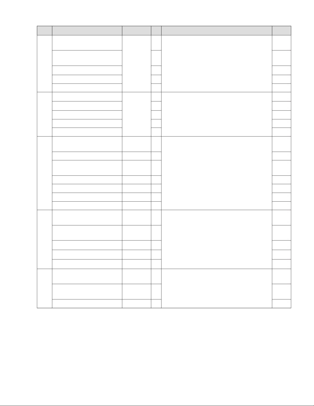
REF NO MODEL PART NUMBER QTY DESCRIPTION PAGE NO
G13, GG13, and PG13
[208 V, 240 V, and 480 V models]
G19, GG19, and PG19
24
[208 V, 240 V, and 480 V models]
G23, GG23, and PG23 [all] 20
G24, GG24, and PG24 [all] 36
G60. GG60, and PG60 [all] 40
G13, GG13, and PG13 [all]
G19, GG19, and PG19 [all] 36
25
G23, GG23, and PG23 [all] 36
G24, GG24, and PG24 [all] 64
G60. GG60, and PG60 [all] 90
G13, GG13, and PG13
[208 V, 240 V, and 480 V models]
G13, GG13, and PG13 [400 V models] G7-46178 2
G19, GG19, and PG19
26
[208 V, 240 V, and 480 V models]
G19, GG19, and PG19 [400 V models] G7-46178 3
G23, GG23, and PG23 [all] G7-32028 12
G24, GG24, and PG24 [all] G7-32028 12
G60. GG60, and PG60 [all] G7-32028 24
G13, GG13, and PG13
[208 V, 240 V, and 480 V models]
G19, GG19, and PG19
27
[208 V, 240 V, and 480 V models]
G23, GG23, and PG23 [all]
2C-35313
2C-31253
G7-32028 4
G7-32028 4
2A-31972 2
2A-31972 2
2A-31971
16
16
23
25
element nut
27
29
31
28
nut
23
25
27
29
31
23
NP
25
thermostat bulb clamp
NP
27
29
31
23
25
thermostat bulb tube
4
27
19
29
31
23
25
29
2M-Z21001 Rev- Owner's Manual for IRCS4 Impingement/Radiant Split-Belt Conveyor Toaster
2M-303339 Rev H Owner’s Manual for Wells Countertop Electric Griddles
G24, GG24, and PG24 [all]
G60. GG60, and PG60 [all]
G13, GG13, and PG13
[208 V, 240 V, and 480 V models]
28
G19, GG19, and PG19
[208 V, 240 V, and 480 V models]
2A-31971
2A-31971
2E-32054 4
2E-32055 4
4
8
element jumper
G24, GG24, and PG24 [all] 2E-32054 8
Page 24
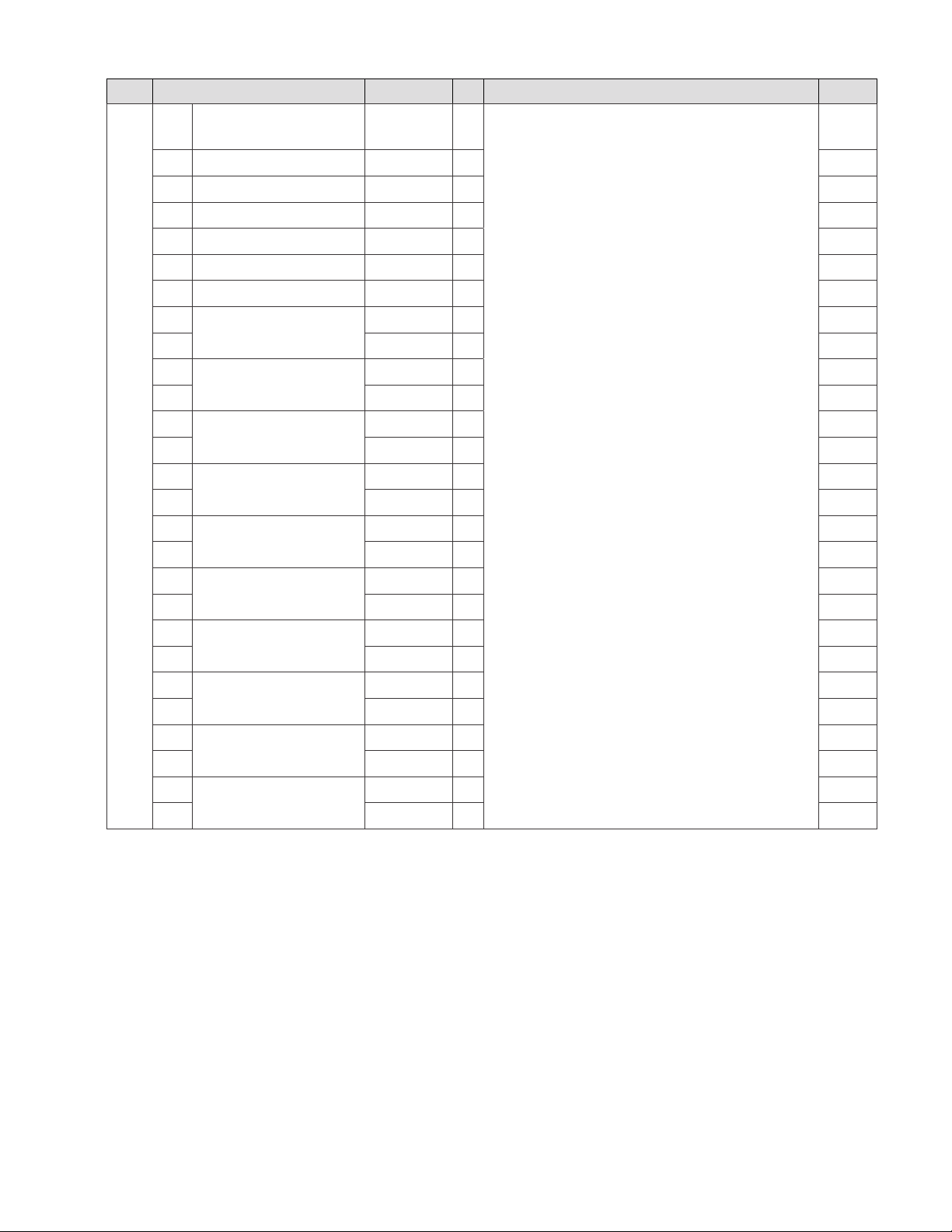
REF NO MODEL PART NUMBER QTY DESCRIPTION PAGE NO
a
G13, GG13, and PG13
[208 V and 240 V]
b G13, GG13, and PG13 [400 V] 2N-45922UL 2
c G13, GG13, and PG13 [480 V] 2N-48904UL 4
d G19, GG19, and PG19 [208 V] 2N-30511UL 4
e G19, GG19, and PG19 [240 V] 2N-30512UL 4
f G19, GG19, and PG19 [400 V] 2N-45922UL 3
g G19, GG19, and PG19 [480 V] 2N-48902UL 4
h
G23, GG23, and PG23 [208 V]
i 2N-30508UL 1
j
i 2N-30508UL 1
G23, GG23, and PG23
[240 V and 400 V]
k
G23, GG23, and PG23 [480 V]
l 2N-31495UL 1
29
r
G24, GG24, and PG24 [208 V]
n 2N-30507UL 1
o
n 2N-30507UL 1
G24, GG24, and PG24
[240 V and 400 V]
p
G24, GG24, and PG24 [480 V]
q 2N-31498UL 1
h
G60, GG60, and PG60 [208 V]
i 2N-30508UL 2
j
G60, GG60, and PG60 [240 V]
i 2N-30508UL 2
j
G60, GG60, and PG60 [400 V]
n 2N-30507UL 2
k
G60, GG60, and PG60 [480 V]
l 2N-31495UL 2
2N-30496UL 4
2N-30510UL 4
2N-30509UL 4
2N-31428UL 4
2N-30513UL 8
2N-30520UL 8
2N-48903UL 8
2N-30510UL 8
2N-30509UL 8
2N-30509UL 8
2N-31428UL 8
element
23
NP
23
25
25
NP
25
27
27
27
27
27
27
29
29
29
29
29
29
31
31
31
31
31
31
31
31
20
Page 25
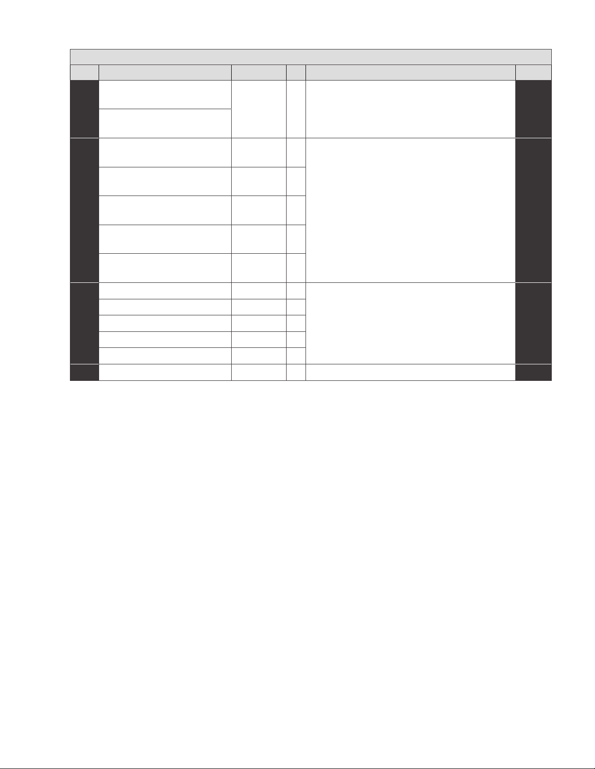
OPTIONAL ACCESSORIES
REF NO MODEL PART NUMBER QTY DESCRIPTION PAGE NO
G13, GG13, and PG13
[208 V, 240 V, and 480 V models]
5D-20563 1 set of four [4] metal legs to replace original plastic legs
G19, GG19, and PG19
[208 V, 240 V, and 480 V models]
G13, GG13, and PG13
[208 V, 240 V, and 480 V models]
G19, GG19, and PG19
[208 V, 240 V, and 480 V models]
G23, GG23, and PG23
[208 V, 240 V, and 480 V models]
G24, GG24, and PG24
[208 V, 240 V, and 480 V models]
G60, GG60, and PG60
[208 V, 240 V, and 480 V models]
2R-Z17209 2
2R-Z17209 2
2R-Z17209 4
2R-Z17209 4
2R-Z17209 8
knob to swap to Celsius units
G13, GG13, and PG13 [400 V models] 2R-300356 2
G19, GG19, and PG19 [400 V models] 2R-300356 3
G23, GG23, and PG23 [400 V models] 2R-30259 4
knob to swap to Fahrenheit units
G24, GG24, and PG24 [400 V models] 2R-30259 4
G60, GG60, and PG60 [400 V models] 2R-30259 8
GG13, GG19, GG23, GG24, GG60 [all] 5G-20651 1 scraper for grooved surface griddle
21
2M-Z21001 Rev- Owner's Manual for IRCS4 Impingement/Radiant Split-Belt Conveyor Toaster
2M-303339 Rev H Owner’s Manual for Wells Countertop Electric Griddles
Page 26
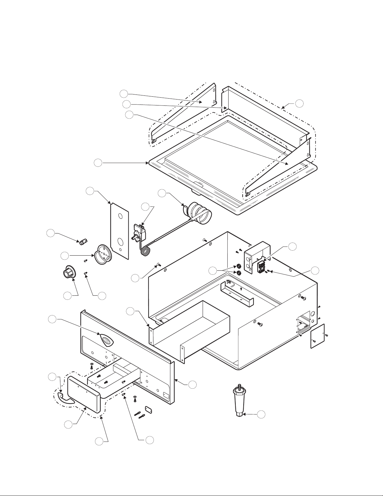
EXPLODED VIEW
G13 BODY [This unit is a 208 V and while many locations
and appearances are similar, some units, such as 400 V
models, may dier.]
1a
1b
1c
2
1
5
6
7
16
9
10
8
13
3
4
18
17
19
22
12a
12b
11
15
12
14
Page 27
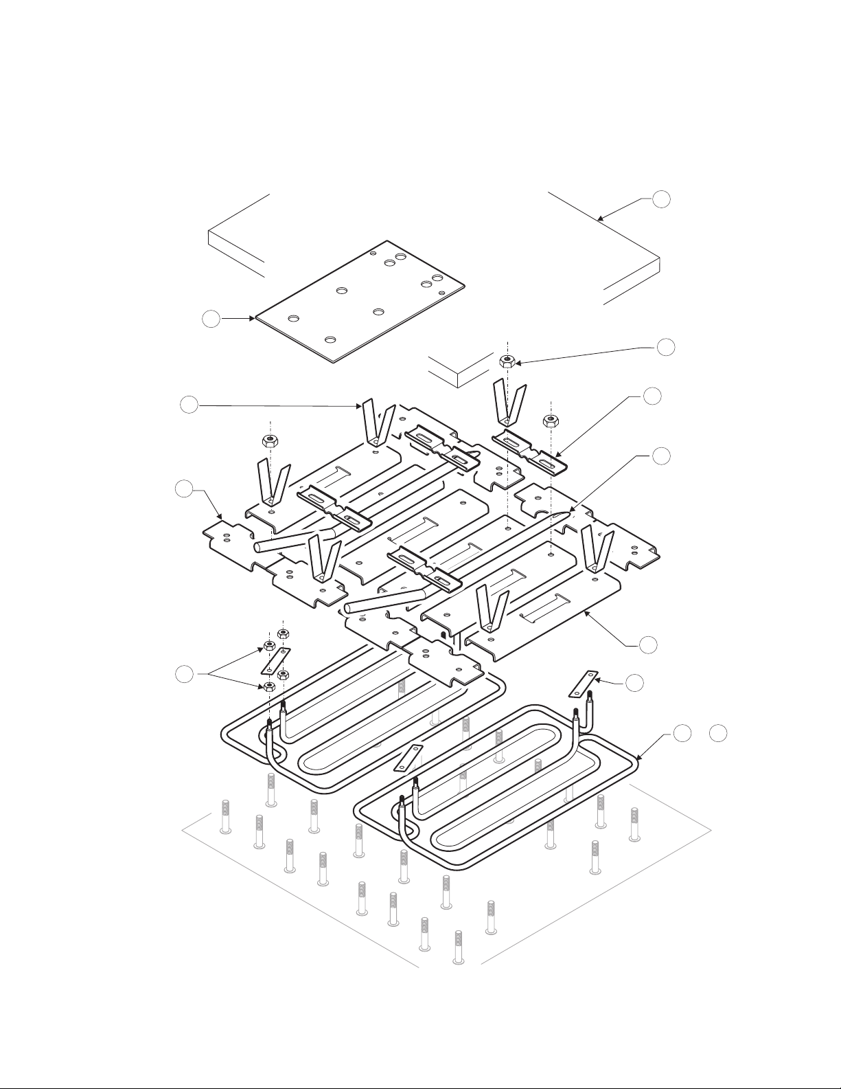
EXPLODED VIEW
G13 INTERNAL [This unit is a 208 V and while many
locations and appearances are similar, some units,
such as 400 V models, may dier.]
21
20
25
23a
22
24
26
27
23b
28
29a 29c
or
front
left
23
2M-Z21001 Rev- Owner's Manual for IRCS4 Impingement/Radiant Split-Belt Conveyor Toaster
2M-303339 Rev H Owner’s Manual for Wells Countertop Electric Griddles
Page 28
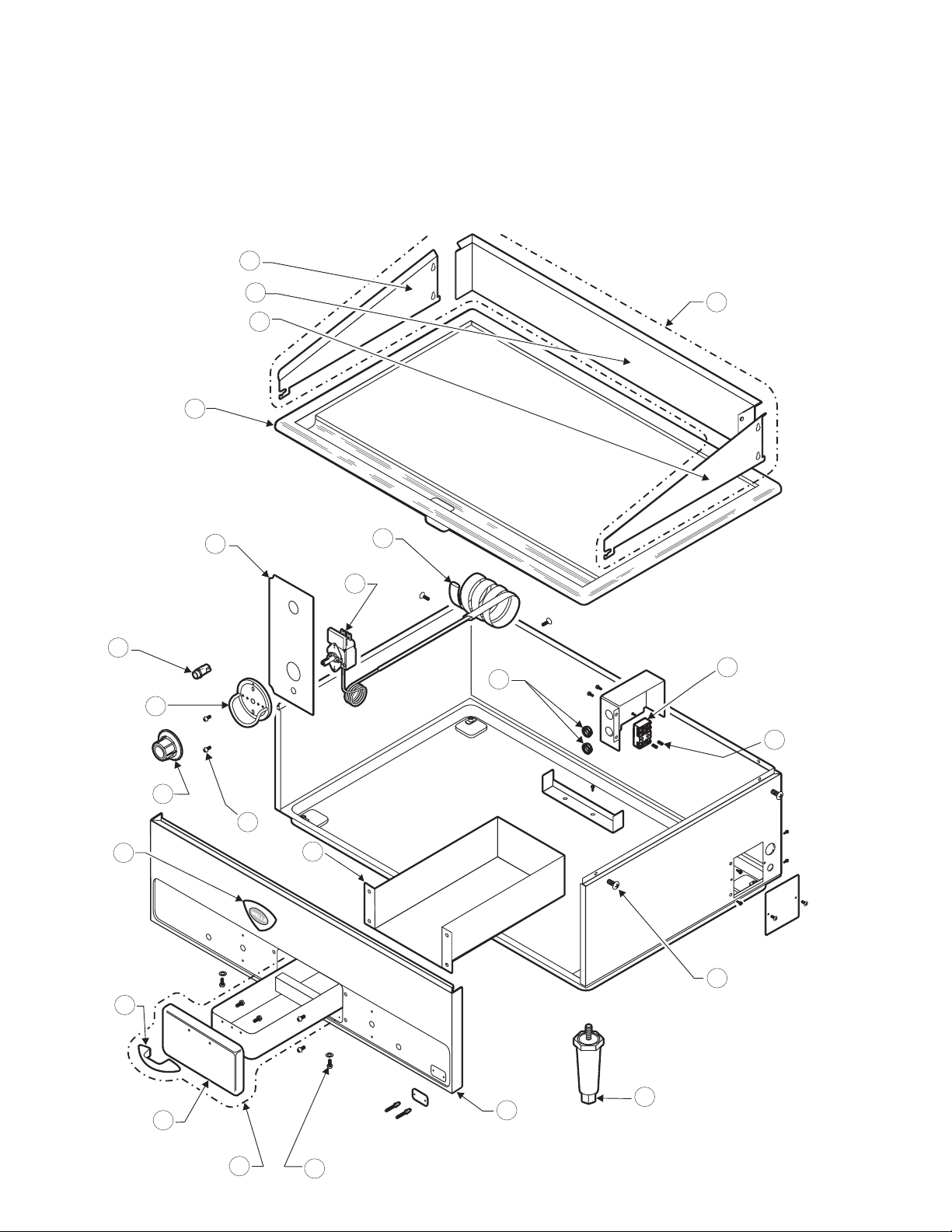
EXPLODED VIEW
G19 INTERNAL [This unit is a 208 V and while many
locations and appearances are similar, some units,
such as 400 V models will dier as, for example
they have 3 thermostats and use a dierent style
of thermostat.
1a
1b
1c
2
5
6
7
3
4
17
1
18
19
24
12a
9
8
10
12b
12
13
16
15
11
14
Page 29
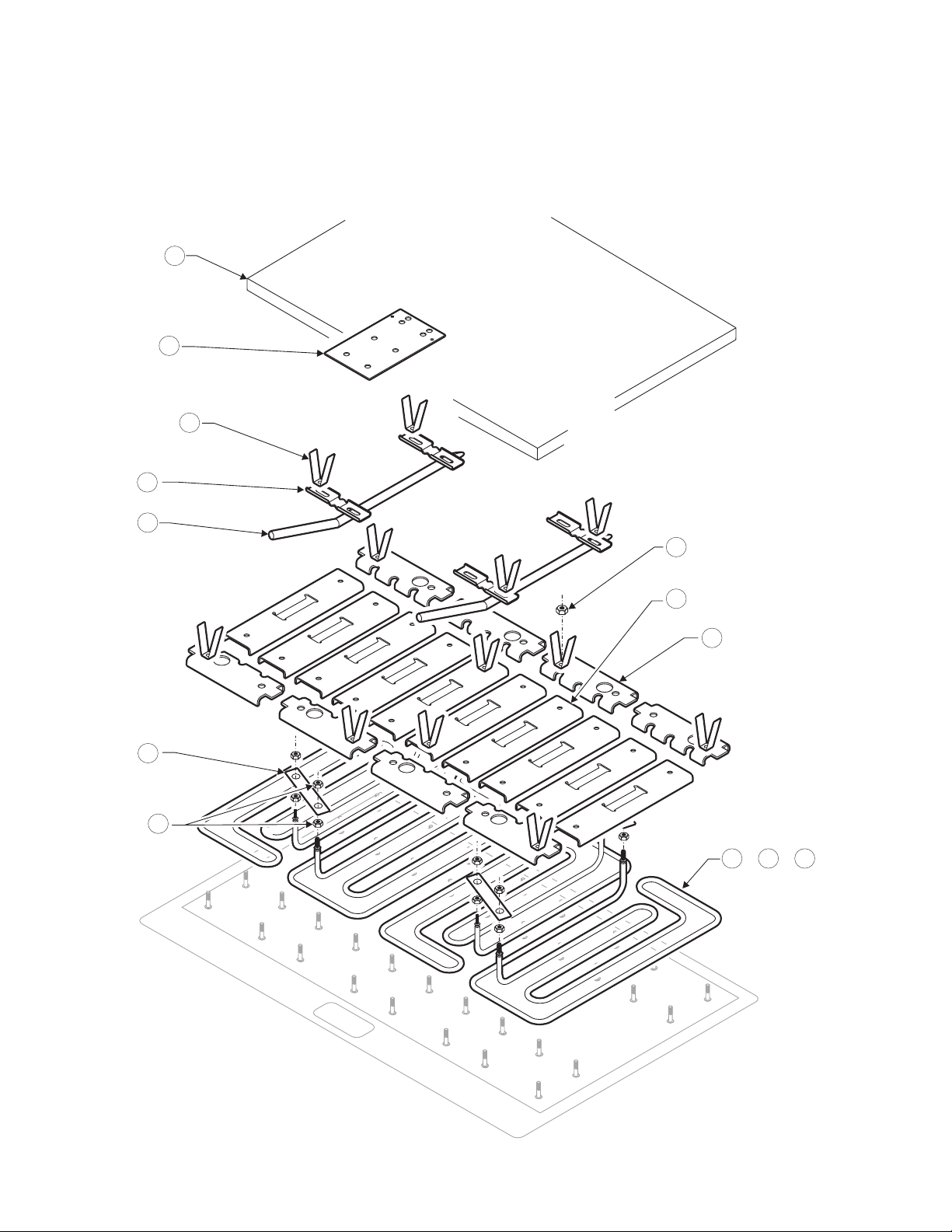
EXPLODED VIEW
G19 INTERNAL [This unit is a 208 V and while many
locations and appearances are similar, some units,
such as 400 V models will dier as, for example they
have 3 elements and use a dierent style of element.]
20
21
22
26
27
25
23b
23c
28
24
or or
29d 29e 29g
front
left
25
2M-Z21001 Rev- Owner's Manual for IRCS4 Impingement/Radiant Split-Belt Conveyor Toaster
2M-303339 Rev H Owner’s Manual for Wells Countertop Electric Griddles
Page 30
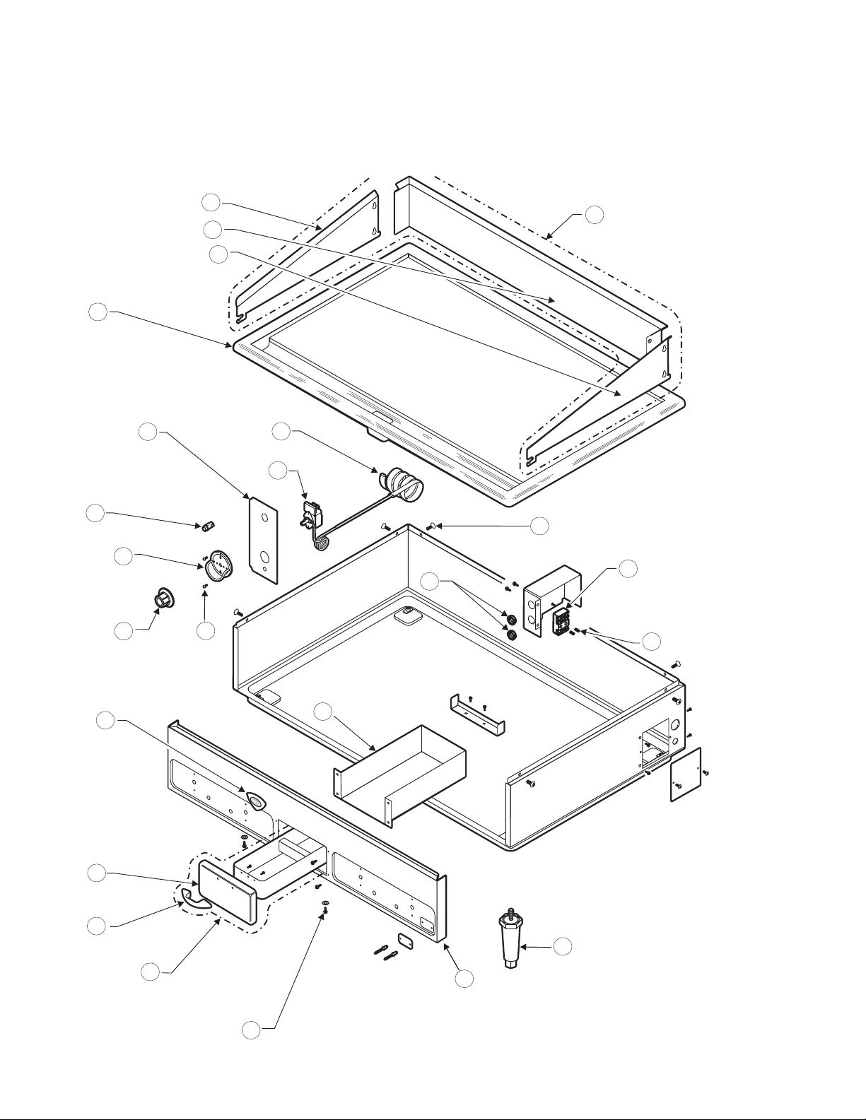
EXPLODED VIEW
G23 BODY [This unit is a 208 V and while many locations
and appearances are similar, some units, such as 400 V or
480 V models, may dier.]
1a
1b
1c
2
5
6
7
3
4
16
17
1
18
12b
12a
9
10
12
8
13
15
11
14
19
26
Page 31
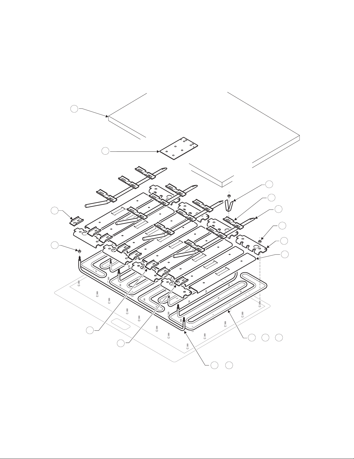
EXPLODED VIEW
G23 INTERNAL [This unit is a 208 V and while many
locations and appearances are similar, some units,
such as 400 V or 480 V models, may dier.]
20
21
22
26
23g
27
25
24
front
23h
23f
left
29i 29l
or
29j29h
23c
23e
oror
29k
27
2M-Z21001 Rev- Owner's Manual for IRCS4 Impingement/Radiant Split-Belt Conveyor Toaster
2M-303339 Rev H Owner’s Manual for Wells Countertop Electric Griddles
Page 32
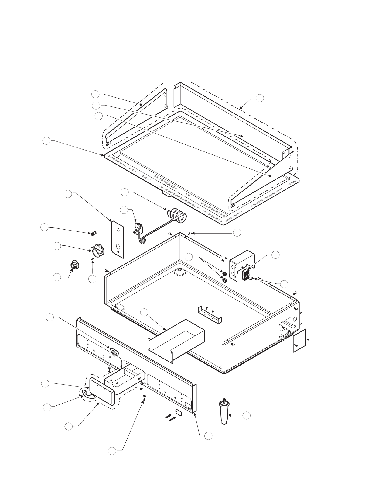
EXPLODED VIEW
G24 BODY [This unit is a 208 V and while many locations
and appearances are similar, some units, such as 400 V or
480 V models, may dier.]
1a
1b
1c
2
5
6
7
3
4
16
17
1
18
12b
12a
9
10
12
8
19
13
15
11
14
28
Page 33
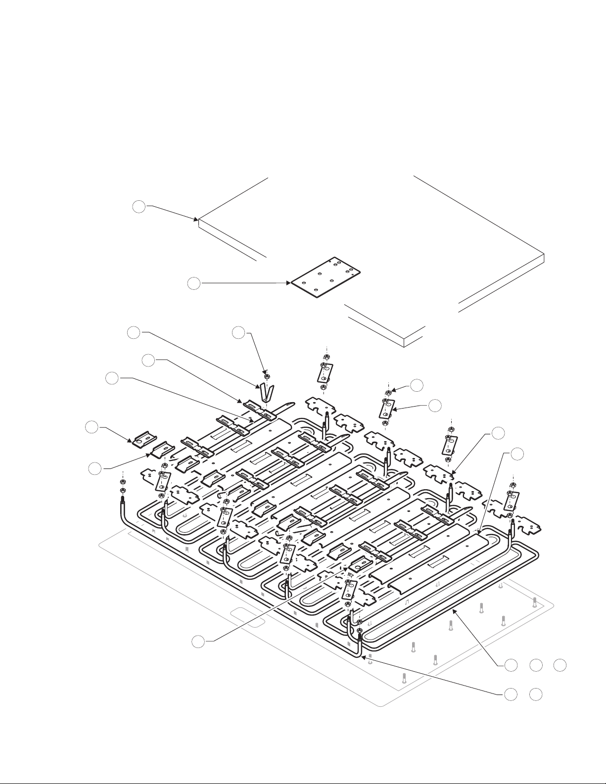
EXPLODED VIEW
G24 INTERNAL [This unit is a 208 V and while many
locations and appearances are similar, some units,
such as 400 V or 480 V models, may dier.]
20
21
22 25
23g
23h
26
27
23f
front
24
28
23a
23e
29o
29p 29r
or or
left
29n
29q
or
2M-Z21001 Rev- Owner's Manual for IRCS4 Impingement/Radiant Split-Belt Conveyor Toaster
29
2M-303339 Rev H Owner’s Manual for Wells Countertop Electric Griddles
Page 34
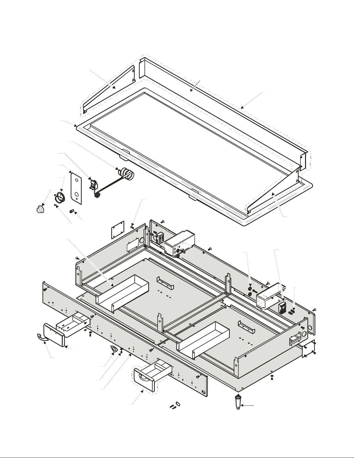
EXPLODED VIEW
G60 BODY [This unit is a 208 V and while many locations
and appearances are similar, some units, such as 400 V or
480 V models, may dier.]
30
Page 35
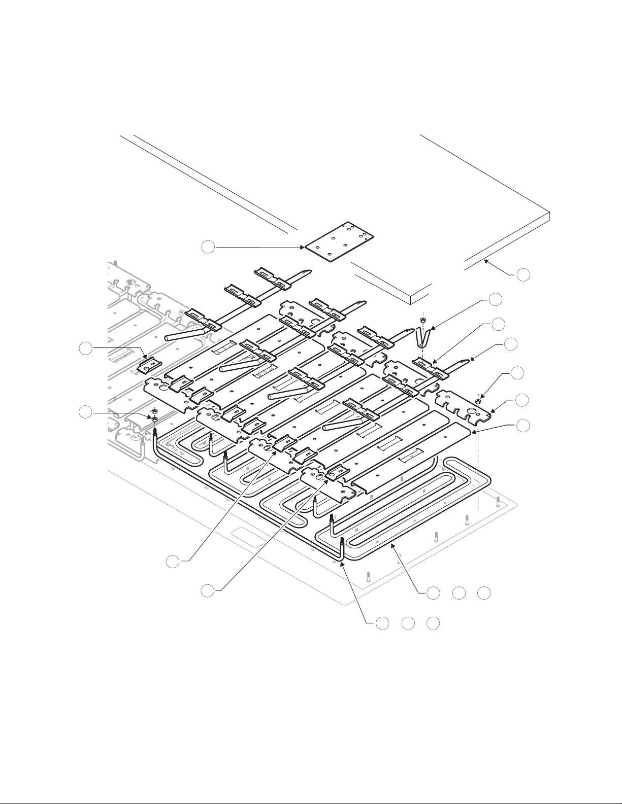
EXPLODED VIEW
G60 INTERNAL [This unit is a 208 V and while many
locations and appearances are similar, some units,
such as 400 V or 480 V models, may dier.]
21
20
22
26
23g
24
23h
27
25
23c
23e
left
front
23f
29i
ororor
29h
29j
29k
or
29l
29n
31
2M-Z21001 Rev- Owner's Manual for IRCS4 Impingement/Radiant Split-Belt Conveyor Toaster
2M-303339 Rev H Owner’s Manual for Wells Countertop Electric Griddles
Page 36

WELLS BLOOMFIELD, LLC • www.wells-mfg.com
10 Sunnen Drive • Saint Louis, Missouri 63143
Telephone 888 356 5362 • Fax 314 781 5445
Printed in the U.S.A. • 2M-303 339 • Rev H • 04.2017
Specifications are subject to change without notice.
 Loading...