

Page 1
WELLS
W E L L S M A N U F A C T U R I N G
I T E M N O .
HT-200AF, HT-300AF, HT-400AF, HT-500AF
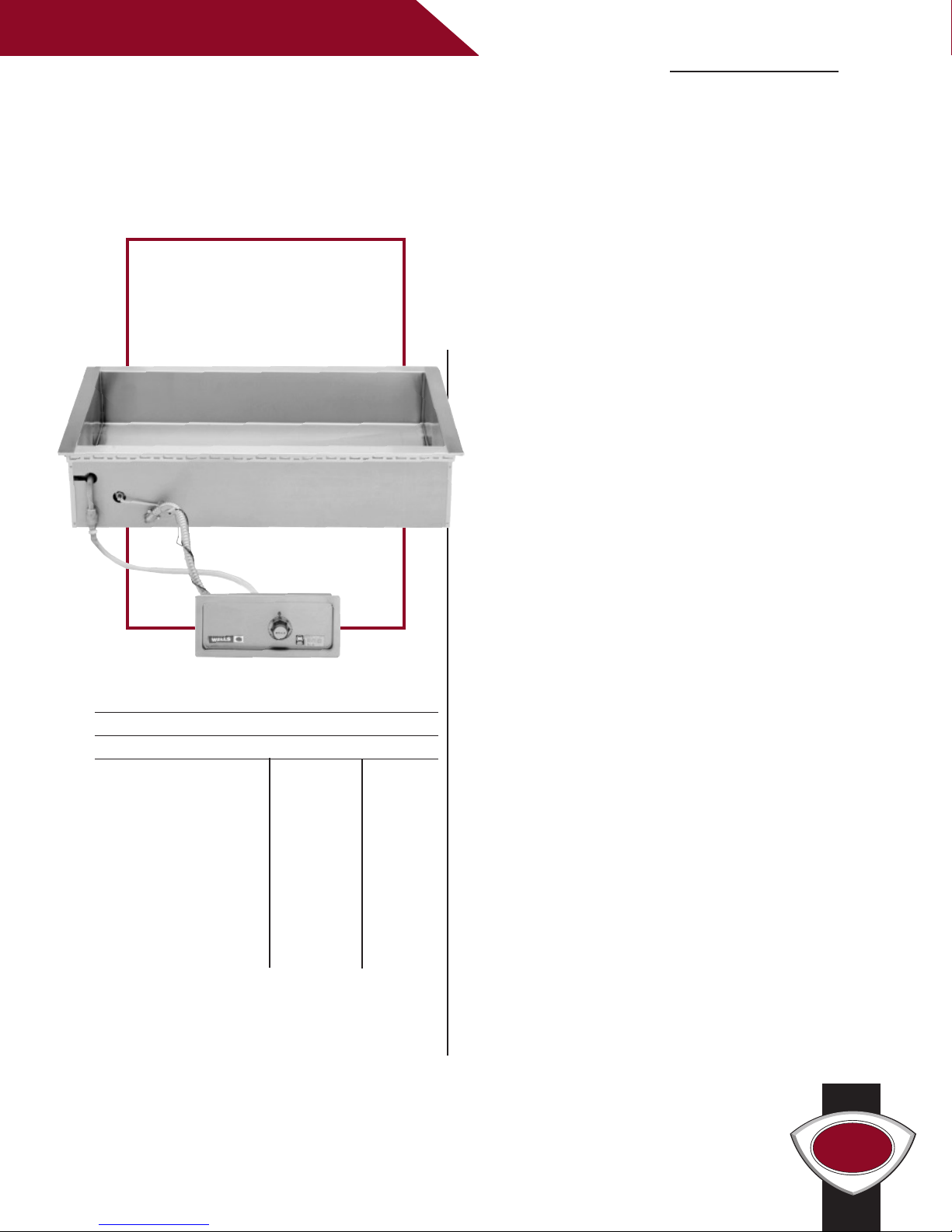
DROP-IN BAIN MARIE WARMERS
The Wells Drop-in Bain Marie Warmers easily meet
your volume needs. The open heated tank can
accommodate two to five standard 12” x 20” inset
HT-200AF
pans, providing product versatility
Features
• All models have an automatic water fill system
(AF) that maintains the proper water level in
each pan through the use of a water sensor and
solenoid valve.
• Interior and top flange is heavy duty (18 gauge)
stainless steel for maximum strength and durability.
.
HT-200AF, HT-300AF, HT-400AF, HT-500AF DROP-IN BAIN MARIE WARMERS
Specifications
Temperature Settings: OFF/LO to HI
Weights: Lbs. KG
HT-200AF series
Installed 49 2
Shipping 59 –
HT-300AF series
Installed 71 32
Shipping 85 39
HT-400AF series
Installed 94 43
Shipping 101 46
HT-500AF series
Installed 101 46
Shipping 122
5
• The positive-off thermostat (T) controls the
element allowing for adjustable and more
consistent temperatures.
• The unit has a large 1-inch drain with screen
located in the center for easy cleaning.
• Adapter bars are included with each unit to allow
the use of a variety of different sized pans.
• Wellslok provides quick and easy installation in
stainless steel countertops.
• Warmers are designed for wet operation only.
2
• The Bain Marie Warmers are Underwriters
Laboratories, Inc. LISTED and meet NSF
International and Canadian standards.
• A one-year warranty against defects covers parts
and labor.
Accessories / Options
5
Wellslok Extension Kit, designed for installation
in a variety of countertops up to 1 1/2˝ thick, refer
to installation instructions, 22593
R A I S I N G T H E S T A N D A R D
Drain Screen, 21709
Optional 72˝ Wiring, for thermostatically
controlled warmers
Page 2
WELLS
WELLS
(98)
3 7/8
(356)
14
(248)
9 3/4
(159)
6 1/4
(505)
19 7/8
(600)
23 5/8
(749)
29 1/2
(654)
25 3/4
FILL CONNECTION
1/4 NPT WATER
W/ BALL VALVE
1" NPT DRAIN
FLEXIBLE CONDUIT
CONTROL PANEL WITH
FLEXIBLE CONDUIT
CONTROL PANEL WITH
W/ BALL VALVE
1" NPT DRAIN
FILL CONNECTION
1/4 NPT WATER
(1010)
39 3/4
(1105)
43 1/2
(600)
23 5/8
(505)
19 7/8
(159)
6 1/4
(248)
9 3/4
(356)
14
(98)
3 7/8
E6070
C
R
R R
LISTED
STD.4
E6070
LISTED
E6070
C
R
R R
LISTED
STD.4
E6070
LISTED
W E L L S M A N U F A C T U R I N G
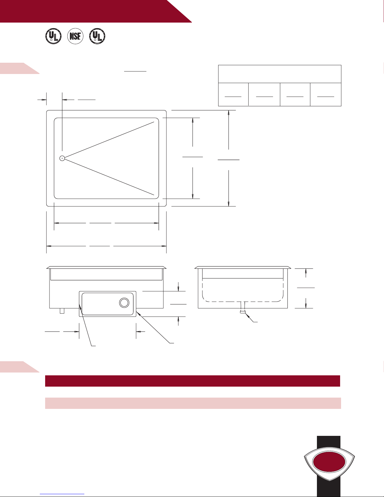
M O D E L H T - 2 0 0 A F
B A I N M A R I E S T Y L E H E A T E D TA N K
W I T H A U T O M A T I C WA T E R F I LL
D I M E N S I O N S :
INCH
(MM)
MINIMUM CLEARANCE REQUIRED
UNIT TO NEAREST SURFACE
BACK SIDE BOTTOM FRONT
1 1 6 3/4 4 1/8
(25) (25) (171) (105)
H T - 2 0 0 A F E L E C T R I C A L S P E C I F I C AT I O N S :
MODELS VOLTS WATTS AMPS PHASE POWER SUPPLY CORD
HT-200AF 208 1800 8.7 SINGLE NONE
HT-200AF 240 2400 10.0 SINGLE NONE
NOTE: Specifications are subject to change without notice. See installation instructions prior to installing the unit.
This document is not for installation purposes.
WELLS MANU FACTU RING COMPANY
2 ERIK C IR CLE, PO B OX 28 0, V ER DI, NV 89439 U.S. A. • US A PH ON E: ( 775) 689-5700 • FAX : (775 ) 689-5972
FOR O RD ER S ON LY: (8 88) 356-536 2 • FAX: (8 00) 356-514 2 • ww w.well sbloo mf ield. com
2001 WELLS M ANU FACTU RIN G • PRI NTE D IN TH E U .S .A. • 2/01 • REV(B ) • PAR T NO. 3 0177 9
Page 3

WELLS
FLEXIBLE CONDUIT
CONTROL PANEL WITH
W/ BALL VALVE
1" NPT DRAIN
FILL CONNECTION
1/4 NPT WATER
(1010)
39 3/4
(1105)
43 1/2
(600)
23 5/8
(505)
19 7/8
(159)
6 1/4
(248)
9 3/4
(356)
14
(98)
3 7/8
E6070
C
R
R R
LISTED
STD.4
E6070
LISTED
W E L L S M A N U F A C T U R I N G
M O D E L H T - 3 0 0 A F
B A I N M A R I E S T Y L E H E A T E D TA N K
W I T H A U T O M A T I C WA T E R F I LL
D I M E N S I O N S :
INCH
(MM)
MINIMUM CLEARANCE REQUIRED
UNIT TO NEAREST SURFACE
BACK SIDE BOTTOM FRONT
1 1 6 3/4 4 1/8
(25) (25) (171) (105)
H T - 3 0 0 A F E L E C T R I C A L S P E C I F I C AT I O N S :
MODELS VOLTS WATTS AMPS PHASE POWER SUPPLY CORD
HT-300AF 208 2700 13.0 SINGLE NONE
HT-300AF 240 3600 15.0 SINGLE NONE
NOTE: Specifications are subject to change without notice. See installation instructions prior to installing the unit.
This document is not for installation purposes.
WELLS MANU FACTU RING COMPANY
2 ERIK C IR CLE, PO B OX 28 0, V ER DI, NV 89439 U.S. A. • US A PH ON E: (775) 689-5700 • FA X: ( 775) 689-5972
R ORDER S ONLY: (888) 3 56- 536 2 • FAX : (800) 3 56- 5142 • www.we llsbl oomfi el d.com
FO
2001 WELLS M ANU FACTU RIN G • PRI NTE D IN TH E U .S .A. • 2/01 • REV(B ) • PAR T NO. 3 0177 9
Page 4

WELLS
E6070
C
R
R R
LISTED
STD.4
E6070
LISTED
WELLS
(159)
6 1/4
(98)
3 7/8
(505)
19 7/8
(1365)
53 3/4
(1461)
57 1/2
(457)
18
(248)
9 3/4
FLEXIBLE CONDUIT
CONTROL PANEL WITH
W/ BALL VALVE
1" NPT DRAIN
FILL CONNECTION
1/4 NPT WATER
(600)
23 5/8
W/ BALL VALVE
1" NPT DRAIN
WITH FLEXIBLE CONDUIT
CONTROL PANEL
(159)
6 1/4
(248)
9 3/4
(457)
18
(1816)
71 1/2
(1721)
67 3/4
(505)
19 7/8
(600)
23 5/8
(98)
3 7/8
W E L L S M A N U F A C T U R I N G
M O D E L S H T- 4 0 0 A F, H T - 5 0 0 A F
B A I N M A R I E S T Y L E H E A T E D TA N KS
W I T H A U T O M A T I C WA T E R F I LL
D I M E N S I O N S :
INCH
(MM)
MINIMUM CLEARANCE REQUIRED
UNIT TO NEAREST SURFACE
BACK SIDE BOTTOM FRONT
1 1 6 3/4 4 1/8
(25) (25) (171) (105)
MODEL
HT-400AF
H T - 4 0 0 A F A N D H T - 5 0 0 A F E L E C T R I C A L S P E C I F I C AT I O N S :
MODELS VOLTS WATTS
HT-400AF 208 3600 8.7 15.0 8.7 17.3 NONE
HT-400AF 240 4800 10.0 17.3 10.0 20.0 NONE
HT-500AF 208 4500 13.0 18.7 8.7 21.7 NONE
HT-500AF 240 6000 15.0 21.7 10.0 25.0 NONE
NOTE: Specifications are subject to change without notice. See installation instructions prior to
installing the unit. This document is not for installation purposes. Units are shipped three phase
and are field convertible to single phase.
WELLS MANU FACTU RING COMPANY
2 ERIK C IR CLE, PO B OX 28 0, V ER DI, NV 89439 U.S. A. • US A PH ON E: ( 775) 689-5700 • FAX : (775 ) 689-5972
FOR O RD ER S ON LY: (8 88) 356-536 2 • FAX: (8 00) 356-514 2 • ww w.well sbloo mf ield. com
2001 WELLS M ANU FACTU RIN G • PRI NTE D IN TH E U .S .A. • 2/01 • REV(B ) • PAR T NO. 3 0177 9
AMPS PER LI NE PHASE 3 AMPS SI NGLE POWER
L1 L2 L3
MODEL
HT-500AF
PHASE SU PPLY CORD
 Loading...