

Page 1
W E L L S M A N U FA C T U R I N G
I T E M N O .
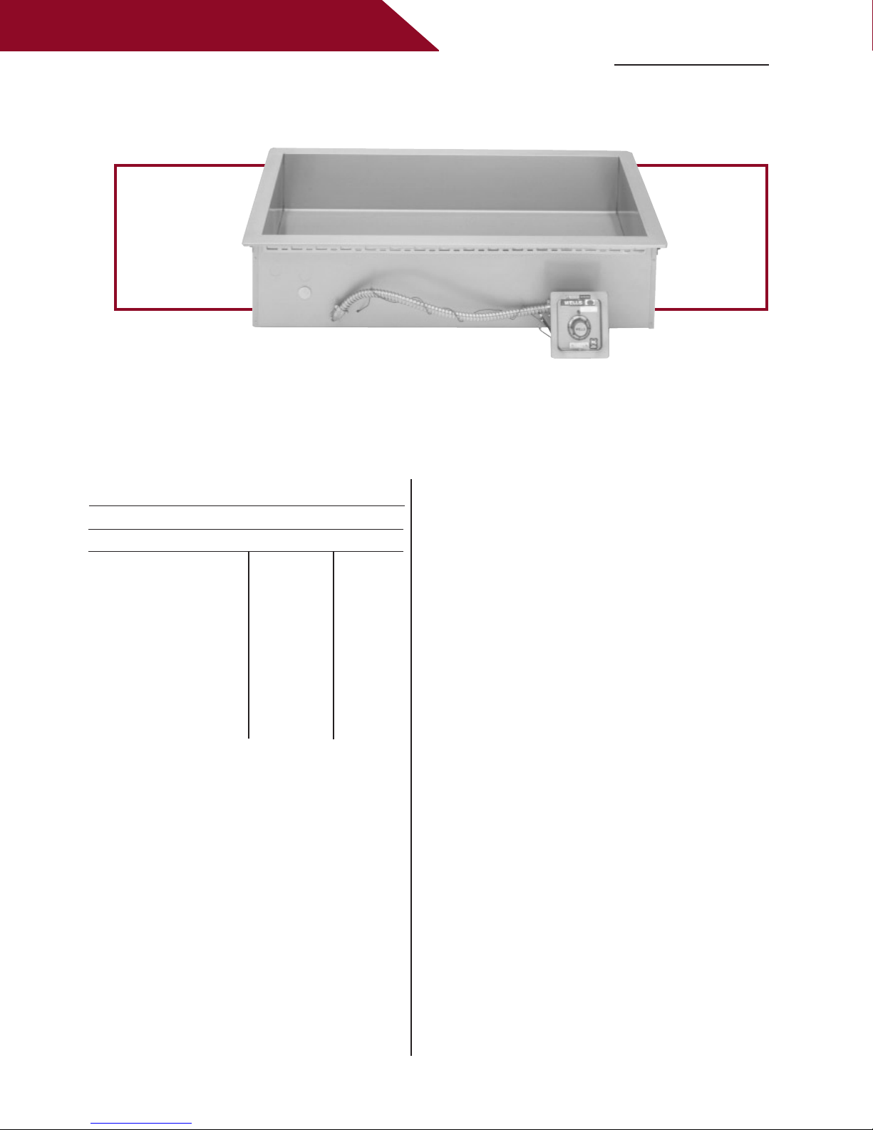
HT-200 - HT-500 BAIN MARIE WARMERS
HT-300
Wells Drop-in Bain Marie Warmers economically meet your volume needs. The versatile heated
tank can accommodate a variety of round or rectangular insets. The heavily insulated single
warming pan and large water volume provide consistent temperatures.
HT-200 - HT-500 BAIN MARIE WARMERS
Specifications
Temperature Settings: OFF/LO to HI
Weights: Lbs. KG
HT-200 series:
Installed 4
Shipping 51 23
HT-300 series:
Installed 63 29
Shipping 73 33
HT-400 series:
Installed 85 38
Shipping 95 43
HT-500 series:
Installed 94 43
Shipping 105 48
1 19
Accessories / Options
Wellslok Extension Kit, designed for
installation in countertops up to 1-1/2” thick,
refer to installation instructions, 22593
Drain Screen, 21709
Optional 72” Wiring, thermostatically
controlled warmers, priced per well
(standard length is 24”)
Features
• The positive-off thermostat controls the
element allowing for adjustable and more
consistent temperatures. A signal light indicates
that the heating element is energized.
• Control is recessed in a one-piece, drawn,
stainless steel panel to help prevent accidental
temperature changes.
• Each unit has a large 1-inch drain with
removable screen for easy cleaning.
• Interior and top flange are heavy-duty
(18 gauge) stainless steel for maximum
strength and durability
• Adapter bars are included with each unit
to allow the use of a variety of different
sized pans.
• The Bain Marie warmers are designed for
wet operation only.
• Wellslok allows for quick and easy installation
in stainless steel countertops.
• The Bain Marie Warmers are Underwriters
Laboratories, Inc. LISTED and meet NSF
International and Canadian standards.
• A one-year warranty against defects covers
parts and labor.
Page 2
W E L L S M A N U FA C T U R I N G
C
R
R R
LISTED
STD.4
E6070
LISTED
(98)
3 7/8
(149)
5 7/8
(248)
9 3/4
(159)
6 1/4
(505)
19 7/8
(600)
23 5/8
W/ BALL VALVE
1" NPT DRAIN
FLEXIBLE CONDUIT
CONTROL PANEL WITH
A
B
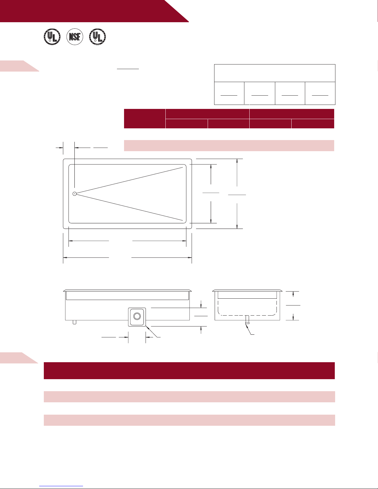
M O D E L S
H T- 2 0 0 , H T- 3 0 0
B A I N M A R I E W A R M E R S
D I M E N S I O N S :
INCH
(MM)
MODELS
DI MENSION 'A' DI MENSION 'B'
INCHES M M INCHES MM
MINIMUM CLEARANCE REQUIRED FROM
UNIT TO THE NEAREST SURFACE
BACK SIDE BOTTOM FRONT
1 1 6 3/4 4 1/8
(25) (25) (171) (105)
HT-200 25 3/4 654 29 1/2 749
HT-300 39 3/4 1010 43 1/2 1105
H T- 2 0 0 , H T- 3 0 0 E L E C T R I C A L S P E C I F I C AT I O N S :
MODELS VOLTS WATTS
HT-200 208 1800 8.7 SINGLE NONE
HT-200 240 2400 10.0 SINGLE NONE
HT-300 208 2700 13.0 SINGLE NONE
HT-300 240 3600 15.0 SINGLE NONE
NOTE: Specifications are subject to change without notice. See installation instructions prior to installing the unit.
This document is not for installation purposes.
AMPS PHASE
POWER
SU PPLY CORD
Page 3

W E L L S M A N U FA C T U R I N G
E6070STD.4
R
E6070
R
LISTED
R
(98)
3 7/8
(159)
6 1/4
(600)
23 5/8
(505)
19 7/8
(1365)
53 3/4
(1461)
57 1/2
(356)
14
(248)
9 3/4
FLEXIBLE CONDUIT
CONTROL PANEL WITH
W/ BALL VALVE
1" NPT DRAIN
M O D E L
H T- 4 0 0
B A I N M A R I E W A R M E R
D I M E N S I O N S :
INCH
(MM)
H T- 4 0 0 E L E C T R I C A L S P E C I F I C AT I O N S :
MODELS VOLTS WATTS
HT-400 208 3600 8.7 15.0 8.7 17.3 NONE
HT-400 240 4800 10.0 17.3 10.0 20.0 NONE
NOTE: Specifications are subject to change without notice. See installation instructions prior to installing the unit.
This document is not for installation purposes.
AMPS PER LINE PHASE 3
L1 L2 L3
AMPS POWER
SI NGLE PHASE SUPPLY CORD
Page 4

W E L L S M A N U FA C T U R I N G
E6070STD.4
R
E6070
R
LISTED
R
(159)
6 1/4
(98)
3 7/8
(600)
23 5/8
(505)
19 7/8
(1721)
67 3/4
(1816)
71 1/2
(356)
14
(248)
9 3/4
FLEXIBLE CONDUIT
CONTROL PANEL WITH
W/ BALL VALVE
1" NPT DRAIN
M O D E L
H T- 5 0 0
B A I N M A R I E W A R M E R
D I M E N S I O N S :
INCH
(MM)
H T- 5 0 0 E L E C T R I C A L S P E C I F I C AT I O N S :
MODELS VOLTS WATTS
HT-500 208 4500 13.0 18.7 8.7 21.7 NONE
HT-500 240 6000 15.0 21.7 10.0 25.0 NONE
NOTE: Specifications are subject to change without notice. See installation instructions prior to installing the unit.
This document is not for installation purposes.
WELLS MANUFACTU RI NG COM PANY
2 ERI K C IRC LE, PO BOX 2 80, VERDI, NV 89439 U.S.A .
USA P HON E: (775) 689-5700 • FAX : ( 775) 689-5972
FOR OR DER S ONLY: (888) 356 -536 2 • FAX : ( 800) 35 6-514 2
www. wel lsbl oomfiel d.com
© 2001 W ELLS MANUFAC TU RI NG • P RI NTE D IN T HE U.S. A.
06 /01 • R EV(C) • PA RT NO. 301765
AMPS PER LINE PHASE 3
L1 L2 L3
AMPS POWER
SI NGLE PHASE SUPPLY CORD
 Loading...