

Page 1
W E L L S M A N U FA C T U R I N G
WELLS
I T E M N O .
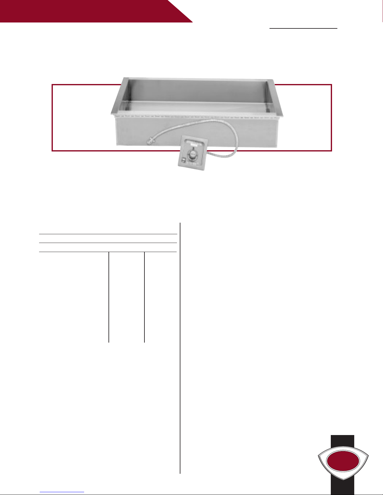
HT-227, HT-327, HT-427, HT-527
DROP-IN BAIN MARIE WARMERS
HT-327
The Wells 12” x 27” Drop-in Bain Marie Warmers economically meet your volume needs,
designed with 33% more capacity than the standard Bain Marie warmers. The versatile heated
tank can accommodate a variety of round or rectangular insets. The heavily insulated single
warming pan and large volume provide consistent temperatures.
HT-227, HT-327, HT-427, HT-527 DROP-IN BAIN MARIE WARMERS
Specifications
Temperature Settings: OFF/LO to HI
Weights: Lbs. KG
HT
-227:
Installed 49 22
Shipping 59 27
HT-327:
Installed 71 32
Shipping 85 39
HT-427:
Installed 94 43
Shipping 101 46
HT-527:
Installed 101 46
Shipping 122 55
Accessories / Options
Wellslok Extension Kit, designed for
installation in a variety of countertops
up to 1-1/2” thick, refer to installation
instructions, 22593
Features
• The positive-off thermostat controls the
element allowing for adjustable and more
consistent temperatures. A signal light indicates
that the heating element is energized.
• Control is recessed in a one-piece, drawn,
stainless steel panel to help prevent accidental
temperature changes.
• Each unit has a large 1-inch drain with
removable screen for easy cleaning.
• Interior and top flange are heavy-duty
(18 gauge) stainless steel for maximum
strength and durability.
• Adapter bars are included with each unit
to allow the use of a variety of different
sized pans.
• The Bain Marie warmers are designed for
wet operation only.
Drain Screen, 21709
Optional 72” Wiring, thermostatically
controlled warmers, priced per well
(standard length is 24”) contact factory.
Wellslok allows for quick and easy installation
•
in stainless steel countertops.
• The Bain Marie Warmers are Underwriters
Laboratories, Inc. LISTED and meet NSF
International and Canadian standards.
• A one-year warranty against defects
covers parts and labor.
Page 2
LISTED
E6070
STD.4
LISTED
RR
R
C
E6070
(98)
3 7/8
(159)
6 1/4
(778)
30 5/8
(683)
26 7/8
A
B
(356)
14
(248)
9 3/4
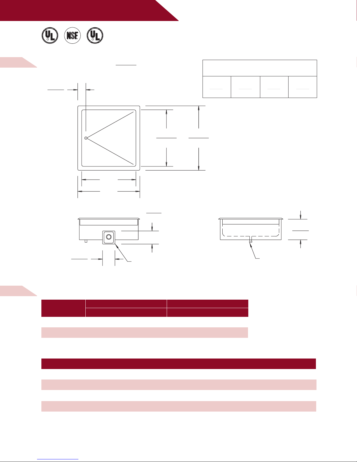
FLEXIBLE CONDUIT
CONTROL PANEL WITH
W/ BALL VALVE
1" NPT DRAIN
W E L L S M A N U FA C T U R I N G
C
R
R R
LISTED
STD.4
E6070
LISTED
E6070
(98)
3 7/8
(149)
5 7/8
(248)
9 3/4
(159)
6 1/4
(683)
26 7/8
(778)
30 5/8
B
A
W/ BALL VALVE
1" NPT DRAIN
FLEXIBLE CONDUIT
CONTROL PANEL WITH
M O D E L S
H T- 2 2 7, H T - 3 2 7
D R O P - I N B A I N M A R I E W A R M E R S
D I M E N S I O N S :
INCH
(MM)
MINIMUM CLEARANCE REQUIRED FROM
UNIT TO THE NEAREST SURFACE
BACK SIDE BOTTOM FRONT
1 1 10 3/4 4 1/8
(25) (25) (273) (105)
D I M E N S I O N S P E C I F I C AT I O N S :
MODELS
HT-227 25 3/4 (654) 29 1/2 (749)
HT-327 39 3/4 (1010) 43 1/2 (1105)
DIMENSION 'A' DIMENSION 'B'
INCHES MM INCHES MM
H T- 2 2 7, H T - 3 2 7 E L E C T R I C A L S P E C I F I C A T I O N S :
MODELS VOLTS WATTS AMPS PHASE POWER SUPPLY CORD
HT-227 208 2500 11.9 SINGLE NONE
HT-227 240 3300 13.8 SINGLE NONE
HT-327 208 3700 17.9 SINGLE NONE
HT-327 240 5000 20.6 SINGLE NONE
NOTE: Specifications are subject to change without notice. See installation instructions prior to installing the unit.
This document is not for installation purposes.
03 /0 2 • RE V(A ) • PART NO. 3 02 96 4
Page 3

W E L L S M A N U FA C T U R I N G
LISTED
E6070
STD.4
LISTED
RR
R
C
E6070
(98)
3 7/8
(159)
6 1/4
(778)
30 5/8
(683)
26 7/8
A
B
(356)
14
(248)
9 3/4
FLEXIBLE CONDUIT
CONTROL PANEL WITH
W/ BALL VALVE
1" NPT DRAIN
M O D E L
H T- 4 2 7
D R O P - I N B A I N M A R I E W A R M E R
D I M E N S I O N S :
INCH
(MM)
MINIMUM CLEARANCE REQUIRED FROM
UNIT TO THE NEAREST SURFACE
BACK SIDE BOTTOM FRONT
1 1 10 3/4 4 1/8
(25) (25) (273) (105)
D I M E N S I O N S P E C I F I C AT I O N S :
MODELS
HT-427 53 3/4 (1365) 57 1/2 (1461)
DIMENSION 'A' DIMENSION 'B'
INCHES MM INCHES MM
H T- 4 2 7 E L E C T R I C A L S P E C I F I C AT I O N S :
MODELS VOLTS WATTS
HT-427 208 5000 11.9 20.0 11.9 23.8 NONE
HT-427 240 6600 13.8 23.8 13.8 27.5 NONE
NOTE: Specifications are subject to change without notice. See installation instructions prior to installing the unit.
This document is not for installation purposes.
03 /0 2 • RE V(A ) • PART NO. 3 00711
AMPS PER LINE 3 PHASE
L1 L2 L3
AMPS POWER
SI NGLE PHAS E SUPPLY CORD
Page 4

WELLS
W E L L S M A N U FA C T U R I N G
LISTED
E6070
STD.4
LISTED
RR
R
C
E6070
(98)
3 7/8
(159)
6 1/4
(778)
30 5/8
(683)
26 7/8
A
B
(356)
14
(248)
9 3/4
FLEXIBLE CONDUIT
CONTROL PANEL WITH
W/ BALL VALVE
1" NPT DRAIN
M O D E L
H T- 5 2 7
D R O P - I N B A I N M A R I E W A R M E R
D I M E N S I O N S :
INCH
(MM)
MINIMUM CLEARANCE REQUIRED FROM
UNIT TO THE NEAREST SURFACE
BACK SIDE BOTTOM FRONT
1 1 10 3/4 4 1/8
(25) (25) (273) (105)
D I M E N S I O N S P E C I F I C AT I O N S :
MODELS
DIMENSION 'A' DIMENSION 'B'
INCHES MM INCHES MM
HT-527 67 3/4 (1721) 71 1/2 (1816)
H T- 5 2 7 E L E C T R I C A L S P E C I F I C AT I O N S :
MODELS VOLTS WATTS
HT-527 208 6200 17.9 25.8 11.9 29.8 NONE
HT-527 240 8300 20.6 29.8 13.8 34.4 NONE
NOTE: Specifications are subject to change without notice. See installation instructions prior to installing the unit.
This document is not for installation purposes.
WELLS MANU FACTURI NG COM PANY
2 ERIK CIRCLE , PO BOX 280 , VERDI, NV 8 9439 U. S.A .
USA PHONE: (775 ) 689-5700 • FAX : (775 ) 689-5972
FOR O RD ER S ON LY: (888) 356-5362 • FA X: ( 800) 356 -5142
www. we lls bloom field .com
© 2002 W ELL S MAN UFACTU RIN G • PR INT ED IN TH E U .S .A.
03 /0 2 • RE V(A ) • PART NO. 3 00711
AMPS PER LINE 3 PHASE
L1 L2 L3
AMPS POWER
SI NGLE PHAS E SUPPLY CORD
 Loading...