

Wells HRCP-7200, HRCP-7300, HRCP-7500, HRCP-7400, HRCP-7600 Installation Instructions Manual
INSTALLATION INSTRUCTIONS
SELF-CONTAINED DROP-IN
HOT AND COLD PAN
MODEL HRCP-7200 THRU 7600
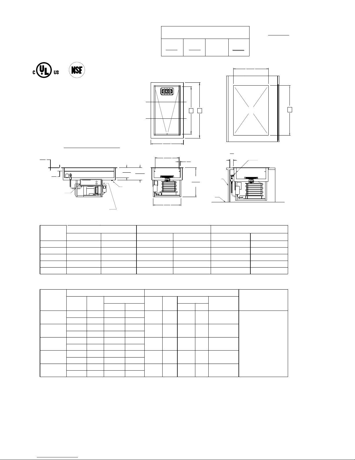
MINIMUM CLEARANCE REQUIRED FROM
UNIT TO THE NEAREST SURFACE.
BACK0SIDE0BOTTOM
(0)
(0)
NA
FRONT
3
(76)
INCHES
(MM)
MEETS NSF STANDARD 7
PERFORMANCE REQUIREMENTS
AT 3" PAN RAIL DEPTH
R
LISTED
R
STD. 7
MODEL HRCP-7300 SHOWN
5/16
(8)
3
(76)
1/4"NPT
WATER LINE
CONNECTION
1 1/8" DIA. CONDUIT
K.O. TERMINAL
BLOCK CONNECTION
DIMENSIONS (INCHES/MM)
MODE
HRCP-7200
HRCP-7300
HRCP-7400
HRCP-7500
HRCP-7600
INCHES MM INCHES MM
32 3/4
46 1/2
60 1/4
74
87 3/4
25 7/8
TOP VIEW
B
A
(657)
CUTOUT
C
27 1/8
8 5/8
10 3/8
(219)
(264)
1"NPT DRAIN
(689)
19
(505)
23
(584)
1
(25)
24 3/8
(620)
FRONT
ACCESS
REQUIRED
FOR
CONTROLS
FLOOR
LEVEL
3
MINIMUM
(76)
CROSS SEC.
FINAL PLUMBING ASSEMBLY.
FOLLOW INSTRUCTIONS ON PAGE 2
SIDE VIEW
31 1/2
45 1/4
59
72 3/4
86 1/2
C (CUTOUT)
800
1149
1499
1848
2197
A
INCHES MM
832
1181
1530
1880
2229
25 1/2
39 1/4
53
66 3/4
80 1/2
B
648
997
1346
1695
2045
ELECTRICAL
W A R M E R
MODEL
HRCP-7200
HRCP-7300
HRCP-7400
HRCP-7500
HRCP-7600
VOLTS
208
240
208
240
208
240
208
240
208
240
KW
1.9
2.5
3.0
4.0
3.8
5.0
6.0
8.0
6.0
8.0
L1 - L2 N
9.0
10.4
14.4
16.7
18.1
20.8
28.9
33.3
28.9
33.3
N.A.
N.A.
N.A.
N.A.
N.A.
N.A.
N.A.
N.A.
N.A.
N.A.
VOLTS
120
120
120
120
120
WELLS MANUFACTURING COMPANY
2 ERIK CIRCLE P.O. BOX 280 * VERDI, NV 89439
1-888-356-5362 * FAX: 1-800-356-5142
PRINTED IN U.S.A. 2003
R E F R I G E R A T I O N
AMPS 1PHAMPS 1-PH
1/4
1/3
1/2
3/4
3/4
HP
L2 - N
5.5
7.0
7.5
15.3
15.3
L1
N.A.
N.A.
N.A.
N.A.
N.A.
REFRIGERANT
TYPE
R-134-A
R-404-A
R-404-A
R-404-A
R-404-A
SINGLE PHASE SUPPLY
3-WIRE 120/208-240V
L1-L2 208-240V
L2-N 120VAC 60HZ
ALL MODELS
PERMANENTLY
CONNECTED
page 1 304924 (-)
INSTALLATION INSTRUCTIONS
SELF-CONTAINED DROP-IN
HOT AND COLD PAN
MODELS HRCP-7200 THRU 7600
INCHES
(MM)
INSTALLATION INSTRUCTIONS
INSTALLER MUST MEET CONDITIONS OF ACCEPTABILITY
OUTLINED BELOW UPON INSTALLATION:
1. This unit may be installed in stainless steel, wood, Formica,
or Corian tables and countertops.
2. This unit requires drain connection. It also requires a
120/208-240 volt single phase power supply connection.
3. When installing the unit it is essential to provide front access
for service and temperature adjustment. It should have openings
to allow for proper air circulation. Opening shall be at least
twice the surface area of the condenser. Improper ventilation will
cause compressor burnout and void the warranty.
TO FABRICATE :
1. Lay out 'cutout' dimensions on countertop or table.
2. Cut out hole. Make certain countertop is flat and level
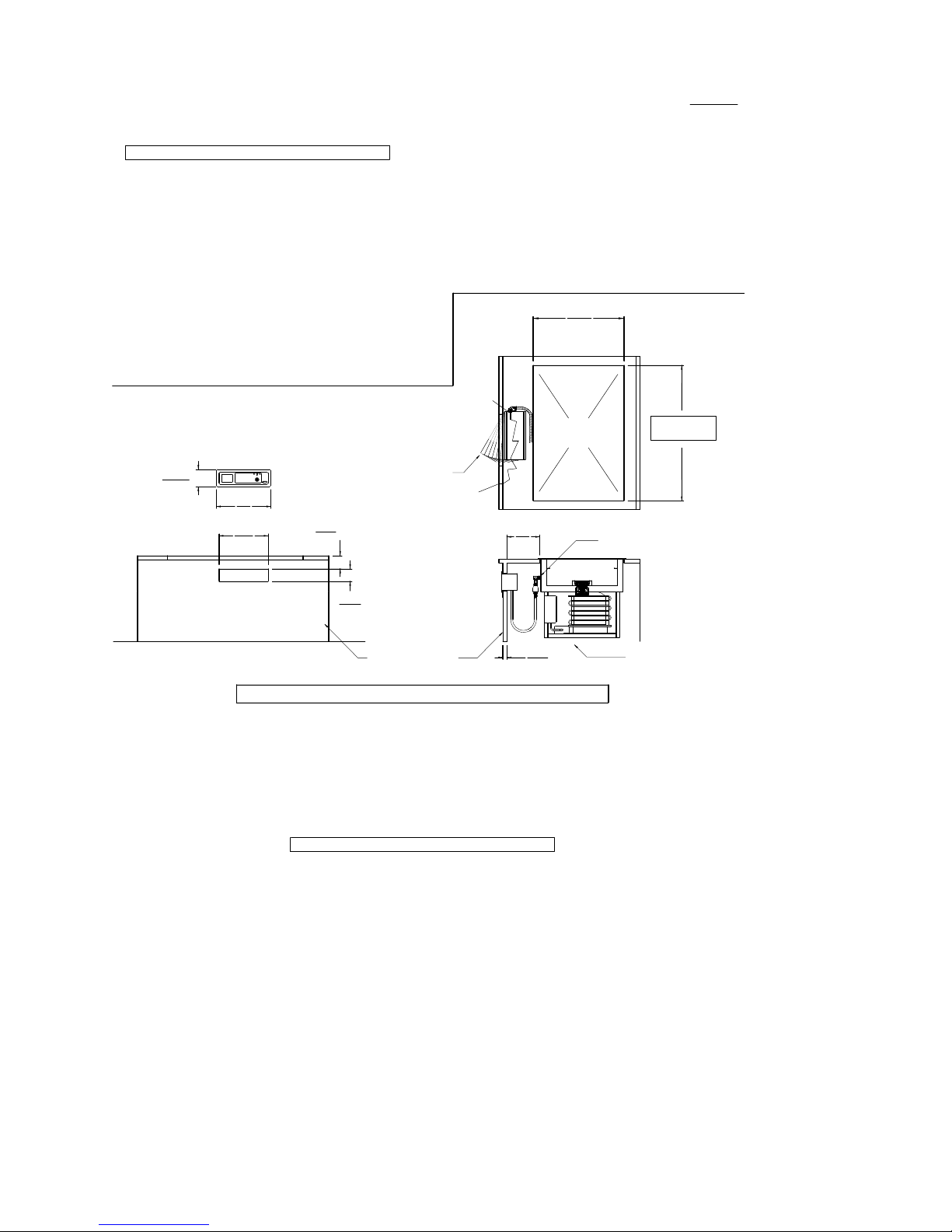
ILLUSTRATION OF
CONTROL PANEL
6 1/4
(159)
FRONT VIEW
18
(457)
17
(441)
ELECTRICAL BOX
POSITIONING AND
ANGLE OF ROTATION IN
ROUTING THRU CUTOUT
3 MINIMUM
(67)
5
(127)
PROVIDE SERVICE
ACCESS BELOW
CONTROL PANEL
REMOTE CONTROL PANEL INSTALLATION INSTRUCTIONS
TO FABRICATE :
1. Lay out "cutout" dimensions on countertop or table.
2. Lay out control panel cutout in the front apron.
Note: Control panel assembly is provided with extra
length of flexible conduit and electric wiring.
This option allows for installation of the
controls outside the enclosure for easy access.
Provide louvered grills service access and temperature
adjustment to the refrigeration system.
PLUMBING AND WIRING INSTRUCTIONS
TO PLUMB :
NOTE: Plumbing connections must be completed after the unit is
lowered onto the counter cutout. The water fill hose with
check valve assembly is shipped disconnected from the tank for
ease of setting unit into the cutout at installation.
1. Apply pipe sealant to the water fill tank fitting and
attach the pre-assembled check valve assembly.
2. Attach water fill hose to hose fitting with hose clamp.
3. Connect 1/4NPT water supply and shut off valve to solenoid
valve in control box. Note: Maximum pressure 120 psi.
Maximim temperature 120°F.
4. A drain valve is supplied with the unit. It is the discretion
of the installer to locate the position of the handle. Connect
1 inch drain to drain pan or floor drain. Valve access must be
provided for draining pan.
side to side and front to back before installing the unit.
3. Provide support from below to reduce load on countertop.
For remote control panel mounting see below.
TO INSTALL :
1. Apply a generous bead of silicone sealant to underside
of mounting flange before setting unit into cutout.
Remove excess sealant from top flange and countertop.
2. Remove thermostat knob and recessed control panel from
control box for access to terminal block.
FOR PLUMBING AND WIRING PLEASE
REFER TO THE BOTTOM OF THIS PAGE
25 7/8
(657)
C
SEE PAGE 1
CROSS SEC.
SIDE VIEW
FLOOR LEVEL
TOP VIEW
MINIMUM
9
(229)
1 MAX
(25)
CUTOUT
WATER FILL PLUMBING
ASSEMBLY. FOLLOW
INSTRUCTIONS BELOW
TO INSTALL :
1. Apply a generous bead of silicone sealant to underside of mounting flange
before setting unit into cutout.
2. Lower the unit into the counter cutout. Wipe clean excess sealant.
3. Remove thermostat knob and recessed control panel from control box.
4. Remove control box assembly from framework. Release wiring conduit from
wire ties and retainers.
5. Install control box (Refer to Top View) by routing it thru the cutout.
6. Fasten control box by using six (6) screws provided.
TO WIRE :
NOTE : MAKE CERTAIN POWER SUPPLY LINE IS
DE-ENERGIZED BEFORE WIRING APPLIANCE.
Unit operates on 120/208-240 volt single phase system. Use #8AWG minimum
60°C supply leads only. Make certain that 'L1 to L2' reads 208 to 240 VAC
and 'L2 to N' reads 120 VAC. Bring supply leads through 1 1/8" conduit K.O.
to terminal block pre-installed in the electrical box.
Install control panel and control knob.
NOTE: INSTALLATION MUST MEET LOCAL PLUMBING AND ELECTRICAL CODES
A backflow preventer check valve is incorporated in unit between water fill solenoid and
pan. Local codes may require additional vacuum break device.
WELLS MANUFACTURING COMPANY
2 ERIK CIRCLE P.O. BOX 280 * VERDI, NV 89439
1-888-356-5362 * FAX: 1-800-356-5142
PRINTED IN U.S.A. 2002
page 2 304924 REV (-)
 Loading...