

Page 1
WELLS MANUFACTURING
265 Hobson Street, Smithville, Tennessee 37166
telephone: 800-264-7827
www.wells-mfg.com
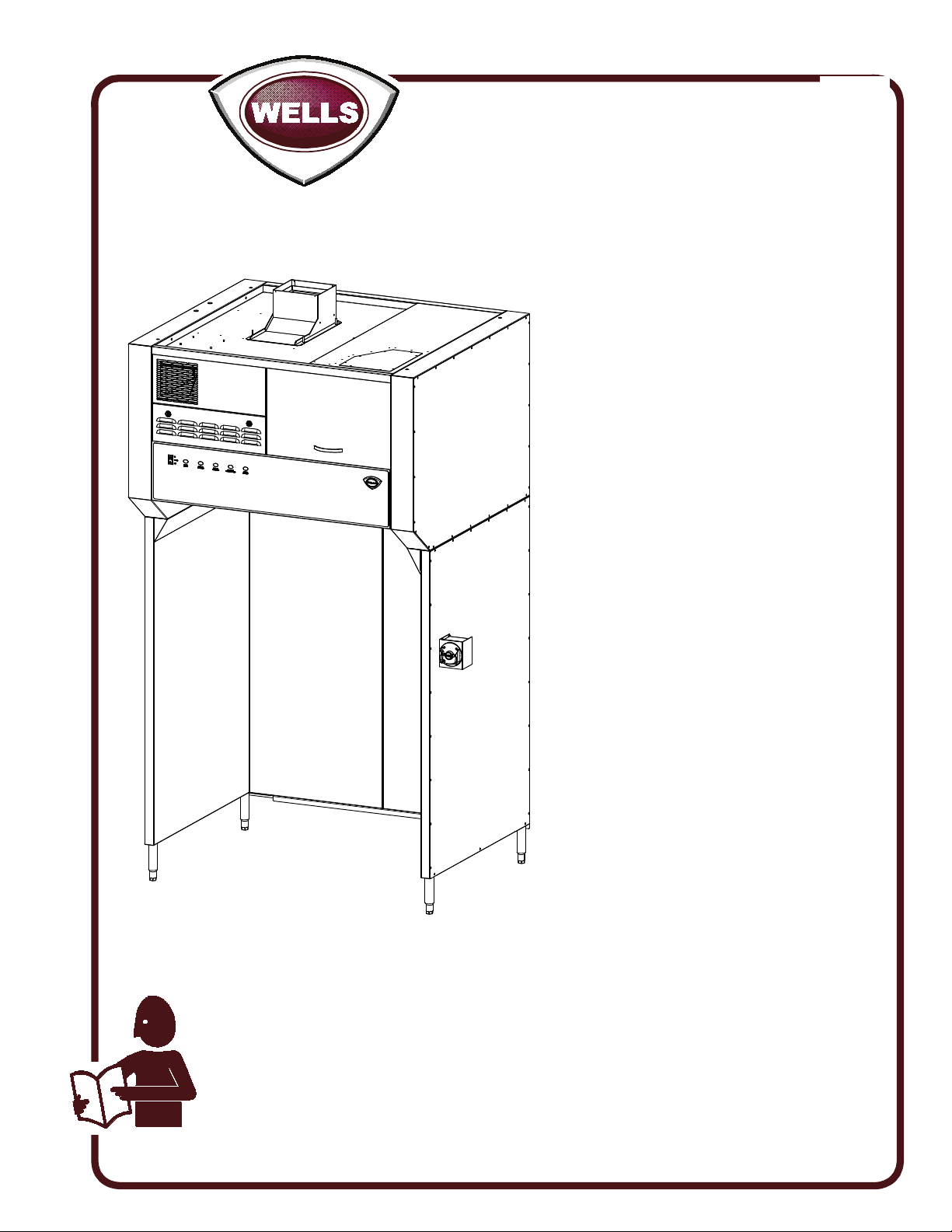
OWNERS MANUAL
VENTLESS UNIVERSAL
HOOD SYSTEM
for
ELECTRIC
COOKING
APPLIANCES
MODEL
522
WVU48
GK48
Manual Includes
INSTALLATION
USE & CARE
EXPLODED VIEW
PARTS LIST
WIRING DIAGRAM
IL2372
IMPORTANT: DO NOT DISCARD THIS MANUAL
This manual is considered to be part of the appliance and is to be given to the OWNER or
MANAGER of the restaurant, or to the person responsible for TRAINING OPERATORS of
this appliance. Additional manuals are available from your WELLS DEALER.
THIS MANUAL MUST BE READ AND UNDERSTOOD BY ALL PERSONS USING OR
INSTALLING THIS APPLIANCE. Contact your WELLS DEALER if you have any
questions concerning installation, operation or maintenance of this equipment.
2M-Z23068 Rev. -
01/2020
Page 2
LIMITED EQUIPMENT WARRANTY
Wells Manufacturing warranties new products to be
free from defects in material and/or workmanship
for a period of one [1] year from the date of original
installation, except as noted below. Defects that occur
as a result of normal use, within the time period and
limitations defined in this warranty, will at Wells’
discretion have the parts replaced or repaired by Wells
or a Wells-authorized service agency.
THIS WARRANTY IS SUBJECT TO ALL LISTED CONDITIONS.
Repairs performed under this warranty are to be
performed by a Wells authorized service agency. Wells
will not be responsible for charges incurred or service
performed by non-authorized repair agencies. In all
cases, the nearest Wells-authorized service agency
must be used. Wells will be responsible for normal
labor charges incurred in the repair or replacement
of a warrantied product within 50 miles (80.5 km)
of an authorized service agency. Time and expense
charges for anything beyond that distance will be
the responsibility of the owner. All labor will need
to be performed during regular service hours. Any
overtime premium will be charged to the owner. For all
shipments outside the U.S.A. and Canada, please see
the International Warranty for specific details. It is the
responsibility of the owner to inspect and report any
shipping damage claims, hidden or otherwise, promptly
following delivery. No mileage or travel charges will be
honored on any equipment that is deemed portable. In
general, equipment with a cord and plug weighing less
than 50 lb. (22.7 kg) is considered portable and should
be taken or shipped to the closest authorized service
agency, transportation prepaid.
CONTACT
Should you require any assistance regarding the
operation or maintenance of any Wells equipment;
, phone,
write
correspondence mention the model number and serial
number of your unit, as well as the voltage or type of
gas you are using.
Business hours are 8:00 a.m. to 4:30 p.m. Central
Standard Time (CST)
Telephone: (800)-264-7827
Fax: (314)-781-2714
Email: [email protected]
www.wells-mfg.com
fax or email our service department. In all
WARRANTY EXCLUSIONS
THE FOLLOWING WILL NOT BE COVERED UNDER WARRANTY.
• Any product which has not been used, cleaned, maintained,
or installed in accordan
appropriate installation sheet and/or owner’s manual as well
as national and local codes, including incorrect gas, electrical,
or water connection. Lang is not liable for any unit which has
been mishandled, abused, misapplied, subjected to chlorides,
harsh chemicals, or caustic cleaners, damaged from exposure
to hard water, modified by unauthorized personnel, damaged
by flood, fire, or other acts of nature [or God], or which have
an altered or missing serial number.
• Installation, labor, and job checkouts, calibration of heat
controls, air and gas burner/bypass/pilot adjustments, gas
or electrical system checks, voltage and phase conversions,
cleaning of equipment, or seasoning of griddle surface.
• Replacement of fuses or resetting of circuit breakers, safety
controls, or reset buttons.
• Replacement of broken or damaged glass components,
quartz heating elements, and light bulbs.
• Labor charges for all removable parts in gas charbroilers
and hotplates, including but not limited to burners, grates,
and radiants.
• Any labor charges incurred by delays, waiting time, or operating restrictions that hinder a service technician’s ability to
perform service.
• Replacement of items subject to normal wear or items that
can easily be replaced during a daily cleaning routine, such as
but not limited to knobs, bulbs, fuses, quartz heating elements, baskets, racks, and grease drawers.
• Components that should be replaced when damaged or
worn, but have been field-repaired instead [eg. field-welded
fry pots]
• Any loss of business or profits.
• Ansul deployments are not covered under warranty.
ADDITIONAL WARRANTIES
• Specific/chain specific versions may also have additional
and/or extended warranties.
ce with the directions published in the
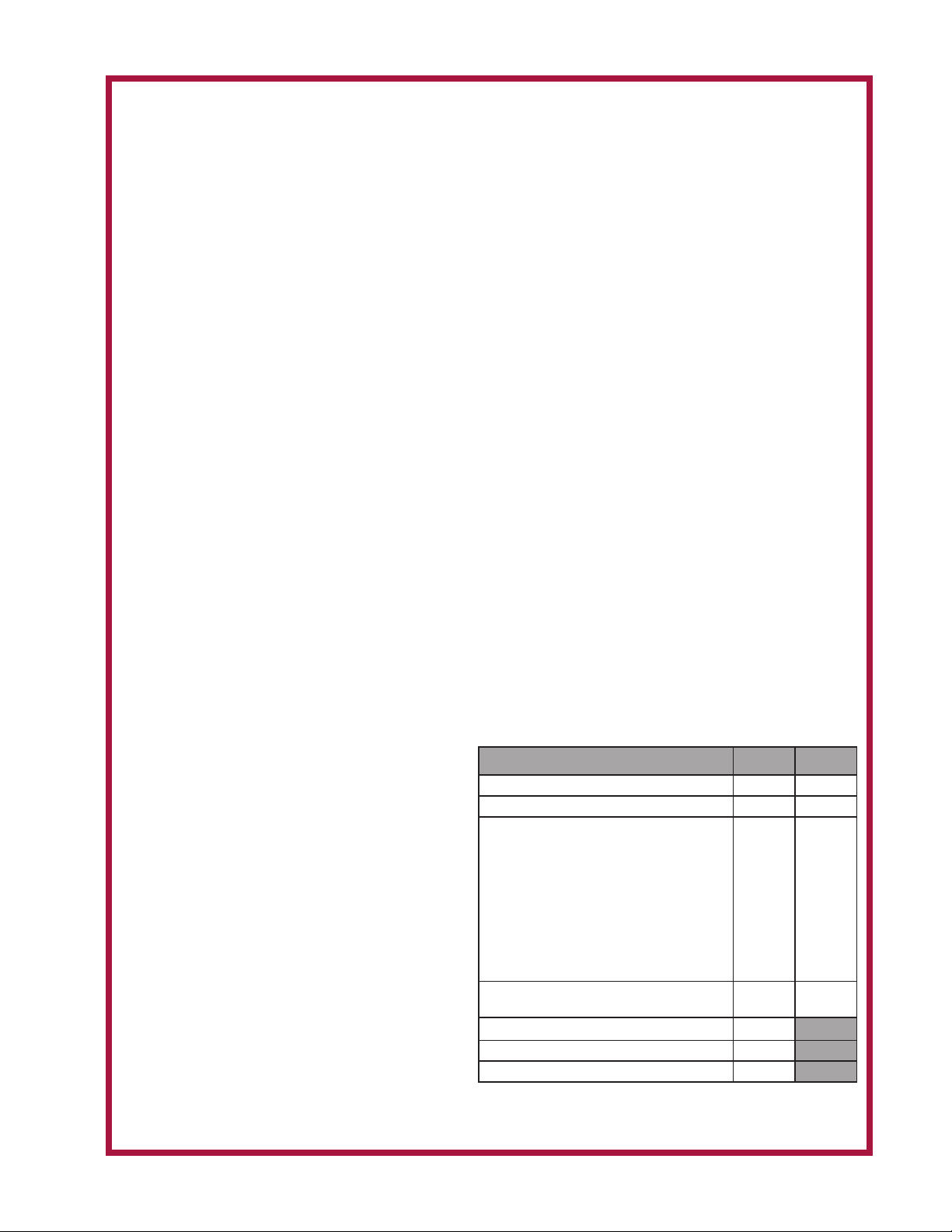
PRODUCTS PARTS LABOR
Universal ventless hoods (WVU)
Canopy ventless hoods (WVC)
*Universal ventless hoods and/or
canopy ventless hoods purchased
with approved Southbend-Star
electric equipment
*Southbend-Star approved electric
equipment purchased and installed
under ventless hood
**Universal Ventless Hood and
Southbend-Star electric equipment
must be on the same PO and listed
on the ventless start-up document
for the 2 year warranty to apply
“Cook’n Hold” equipment [HW10, HWSMP,
LLSC7, LLSC7WA, LLSC11, and LLSC11WA]
Cast iron grates, burners; and burner shields
Wells parts sold to repair equipment 90 days
Service First 1 year
1 year 1 year
1 year 1 year
2 years 2 years
2 years 1 year
1 year
The foregoing warranty is in lieu of any and all other warranties expressed or implied and constitutes the entire warranty.
xi
2M-Z22393 · Rev. B · 01.2019
Page 3

TABLE OF CONTENTS
WARRANTY xi
ELECTRICAL SPECIFICATIONS 1
FEATURES & OPERATING CONTROLS 2-3
PRECAUTIONS & GENERAL INFORMATION 4
AGENCY LISTING INFORMATION 5
INSTALLATION 5
Unpacking & Inspection 5
Components 5
Under-Hood Appliance Limitations 6-7
Service Technician Installation Notes 8-9
Base Assembly 10-24
Under-HoodSpecicLimitations 25-27
Electrical Installation 28-29
ANSUL® INSTALLATION & SETUP 30-31
Filter Installation 32
OPERATION 33
Operation Lights 33
CLEANING INSTRUCTIONS 34-35
DISCHARGE DIRECTION CHANGE 36
REQUIRED MAINTENANCE & MAINTENANCE LOGS 37-41
TROUBLESHOOTING SUGGESTIONS 42
WIRING DIAGRAM 43
EXPLODED VIEW & PARTS LIST 44-53
PARTS & SERVICE 54
CUSTOMER SERVICE DATA 54
APPLICATION FOR VENTLESS APPROVALS 55-56
INTRODUCTION
Thank You for purchasing this Wells Manufacturing appliance.
Proper installation, professional operation and consistent maintenance of this appliance will ensure
that it gives you the very best performance and a long, economical service life.
This manual contains information and instructions for the ventless ventilation hood, its use and care.
For information regarding cooking appliance(s), please refer to the manufacturer’s operation manual.
ELECTRICAL SPECIFICATIONS
Model Volts Hz Amps Power Supply
WVU48/GK48 208/240V 60 Hz 3.5 For supply connection use #12 AWG copper wire only.
M522 p/n 2M-Z23068 OpM WVU- Universal Hood
1
Page 4
FEATURES & OPERATING CONTROLS
20
1
43 5 6
24
15
17
16
19
18
21
22
23
14
13
12 11
2
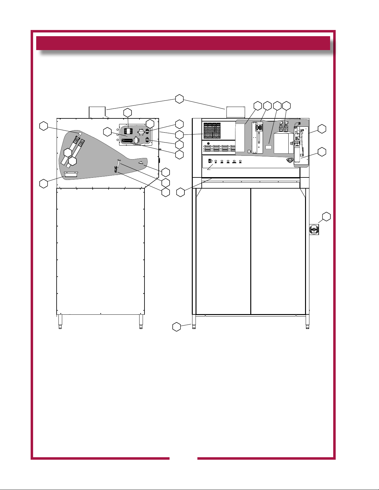
VENTILATOR CONTROL PANEL
see page 15
7
8
9
10
Ventilator Section Operating Features & Controls
2
IL2391a
M522 p/n 2M-Z23068 OpM WVU- Universal Hood
Page 5
FEATURES & OPERATING CONTROLS continued
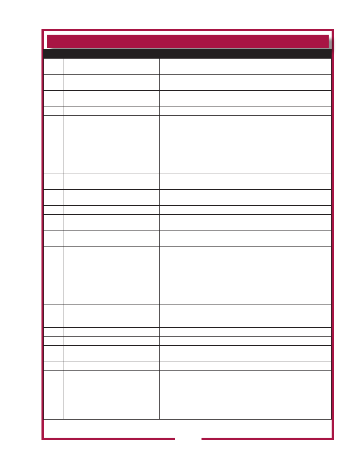
FEATURES & OPERATION CONTROLS
ITEM
NO
VENTILATOR EXHAUST DUCT,
1
TOP
VENTILATOR EXHAUST DUCT,
2
FRONT
3 VENTILATOR FAN Provides air movement for ventilation
HI-EFFICIENCY/CHARCOAL
4
FILTER PACK
5 NAMEPLATE
6 FIRE SUPPRESSION TANK Container for ANSUL®
7 ACTUATOR ASSY
8 ANSUL® CARTRIDGE
9 MANUAL PULL STATION
10 ADJUSTABLE LEGS Allows the unit to be leveled.
11 AIR WALL
12 DISCHARGE NOZZLES
13 ELECTRICAL DETECTORS
14 APPLIANCE LIGHT ON when hood power switch is ON. Illuminates cooking area.
15 GREASE DRIP TRAY
DESCRIPTION COMMENT
Exitpointforventilatorairow-ontopofunit.DO NOT BLOCK
Exitpointforventilatorairow-onfrontofunit. DO NOT BLOCK
Removes grease and smoke particles. Also assists in cooking
odor removal.
Gives manufacturer, make and model description. Also list
voltage and amperage data.
Low-pHLiquidresuppressionuid.
Triggersdeploymentofsuppressionuidthroughmanualpull
station or electric detection.
Propels suppression liquid through suppression manifold and
nozzles.
Providesameansofmanualactivationoftheresuppression
system. PULL ONLY IN CASE OF FIRE!
A wall of air that moves the grease and smoke particles into the
ltersystem.
Fire suppression media discharges here, (6 places 48”, 12
places 96”)
Designedtoactivateatcertaintemperature.Activates(i.e.re
onthecooktop)activatesresuppressionsystem.Shouldbe
checked every 6 months during ANSUL® Service Inspection
Collectsgrease/moisturedrippingfrombafelter(16)
16 BAFFLE FILTER Extractsanddrainsmostgreasesandmoisturefromtheairow.
Comprises the PRE-FILTER FRAME and a replaceable PRE-
17 PRE-FILTER ASSEMBLY
18 ELECTRICAL CONNECTION BOX Houses electrical components
19 GROUND LUG Ground wire of power connection connects here.
EQUIPMENT INTERFACE
20
CONTACTOR
21 BUILDING FIRE ALARM RELAY
DETECTION END OF LINE
22
RELAY
SUPPLY CONNECTION
23
TERMINAL BLOCK
M522 p/n 2M-Z23068 OpM WVU- Universal Hood
24 FILTER INTERLOCK SWITCHES
FILTER. Stops large particles of grease from reaching the
FILTER PACK for reduced maintenance costs.
Energizes cooking appliances only while ventilator section is
sensed as operational.
Reportsrealarmconditiontobuildingremanagementsystem.
Prevents appliance operation if a fault is found in detection
circuit.
Provides connection point for electrical circuitry
Properinstallationofbafelterandlterpackclosesthese
switches in ventilator sensor circuit
3
Page 6
PRECAUTIONS AND GENERAL INFORMATION
This ventilator hood is part of an engineered system and is intended for
use in commercial establishments only.
This ventilator is intended
DANGER:
SUFFOCATION HAZARD
Do not attempt to use this
ventilatorwithgas-redunits.
This ventilator will not remove
products of combustion.
Unvented exhaust gasses
can be deadly.
WARNING:
SHOCK HAZARD
All servicing requiring
access to non-insulated
electrical components must
be performed by a factory
authorized technician.
DO NOT open any access
panel which requires the use
of tools. Failure to follow this
warning can result in severe
electrical shock.
IMPORTANT:
The ventilator is disabled
whentheltersareplugged
tothepointofinsufcient
airowforproperoperation.
Also, power to the cooking
appliances is interrupted if
anyltersorservicepanel
are removed.
It is the responsibility of
the store management to
maintainsufcientspares
oflterpackstoavoid
prolonged shutdown due
toadirtyorcloggedlter
pack. Filter packs cannot be
cleaned.
Wells Manufacturing
assumes no liability for loss
ofbusinessduetoalter
related shutdown. Spare
lterscanbepurchased
from any authorized Wells
servicer or calling Wells.
in the preparation of food for human consumption. No other use is
recommended or authorized by the manufacturer or its agents.
Operators of this appliance must be familiar with the appliance use,
limitations and associated restrictions. Operating instructions must be
read and understood by all persons using or installing this appliance.
This ventilator hood system is designed to reduce odor emissions,
but will not completely eliminate all cooking odors. Air exchange
rates at the installation site must comply with the requirements of the
local jurisdictional authority. To ensure that odors do not accumulate,
recommended minimum air exchange is 200 cfm per linear foot of hood
into and out of the site.
This unit is intended for use with light- and medium duty electric
cooking appliances only. Cooking appliances placed under this
ventilator must comply with the restrictions set forth in the Installation
section of this manual.
Do not connect or energize this appliance until all installation
instructions are read and understood. Property damage or bodily
injury may result if these instructions are not followed. Disconnect this
appliance from electrical power before performing any maintenance or
servicing.
Cleanliness of this appliance is essential to good sanitation. Read and
follow all included cleaning instructions and schedules to ensure the
safety of the food product.
This appliance is not jet steam approved. Do not direct water jet or
steam jet at this appliance, or at any control panel or wiring.
Do not splash or pour water on, in or over any controls, control panel or
wiring.Donotattempttowashlterpacks.Waterwillcausetheir
immediate failure and disable the ventilator.
Exposed surfaces of this appliance can be hot to the touch and may
cause burns.
Avoidstoringammableorcombustiblematerialsin,onornearthe
ventilator or associated cooking appliance.
The technical content of this manual, including any wiring diagrams,
schematics, parts breakdown illustrations and/or adjustment
procedures,isintendedforusebyqualiedtechnicalpersonnel.
Any procedure which requires the use of tools must be performed by a
qualiedtechnician.
All supplied instructions, diagrams, schematics, parts breakdown
illustrations, notices and labels must remain with the appliance if the
unit is sold or moved to another location.
This appliance is made in the USA. Unless otherwise noted, this
appliance has American (SAE) sizes on all hardware.
for commercial establishments for use
M522 p/n 2M-Z23068 OpM WVU- Universal Hood
4
Page 7
AGENCY LISTING INFORMATION
SANITATION
This appliance conforms to NSF Standard 2 for sanitation only if
installed in accordance with the supplied Installation Instructions
and operated and maintained in accordance with the instructions in this
manual.
UL CLASSIFIED for use in US and Canada
NSF/ANSI 2
UL710B
Recurculating System
INSTALLATION
UNPACKING & INSPECTION
Carefully remove the appliance from the carton. Remove all
protectiveplasticlm,packingmaterialsandaccessoriesfromthe
appliance before connecting electrical power or otherwise performing
any installation procedure.
Carefully read all instructions in this manual and any other docments
packed with the appliance before starting any installation.
All documentation should remain with the equipment operator for future
reference.
Read and understand all labels and diagrams attached to the
ventilator.
Carefully account for all components and accessories before
discarding packing materials.
COMPONENTS
4 ft
Pre-Filter 2 ea.
Bafe Filter 2 ea.
Filter pack 1 ea.
Grease cup 1 ea.
Ansul® components - must be installed by an authorized Ansul®
distributor only:
4 ft
2 ea. Fire suppression agent tank
2 ea. Fire suppression agent (Ansulex® Low pH) 1.5 gal.
1 ea. Fire suppression system charging cartridge
Store these components in a convenient place for later use.
Theunitisshippedconguredforhorizontaldischargeoftheexhaust.
To convert to vertical discharge:
1. Remove top access cover.
2. Remove internal turning vane.
3. Insert top discharge scoop assy and fasten w/hardware from cover.
4. Remove front dischage vent panel and damper assy.
5. Assemble damper in Top discharge scoop assy.
M522 p/n 2M-Z23068 OpM WVU- Universal Hood
6. Replace front discharge vent panel.
NOTE: DO NOT discard
the carton or other packing
materials until you have
inspected the appliance for
hidden damage and tested it
for proper operation.
Refer to SHIPPING DAMAGE
CLAIM PROCEDURE on the
inside front cover of this
manual.
WARNING:
RISK OF INJURY
Installation procedures must
beperformedbyaqualied
technician with full knowledge
of all applicable electrical
codes. Failure can result in
personal injury and property
damage.
IMPORTANT:
Fire suppression system must
bechargedandcertiedbyan
authorized Ansul® distributor.
Ventilator will not operate and
cooking appliance will not be
energizeduntiltheAnsul®re
suppression system has been
charged.
IMPORTANT:
After cooking appliances
are positioned under the
hood, swivel nozzles must
be positioned per Ansul®
recommendations.
5
Page 8
INSTALLATION (continued)
WELLS MANUFACTURING
265 HOBSON ST.
SMITHVILLE, TN 37166, USA
UNDER-HOOD APPLIANCE LIMITATIONS:
M522 p/n 2M-Z23068 OpM WVU- Universal Hood
6
Page 9
INSTALLATION (continued)
UNDER-HOOD APPLIANCE LIMITATIONS:
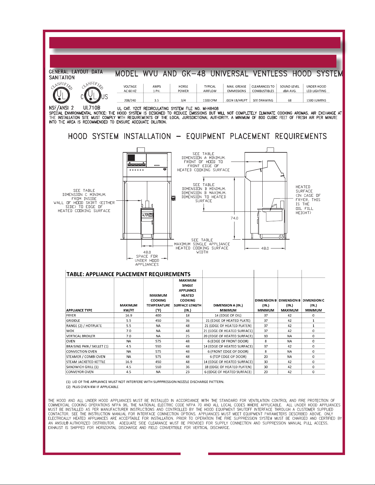
Special instructions: Any Oven or Combi with a vertical exhaust will need a diverter or diffuser to redirect awa from thermal detectors.
M522 p/n 2M-Z23068 OpM WVU- Universal Hood
WELLS MANUFACTURING
265 HOBSON ST.
SMITHVILLE, TN 37166, USA
7
Page 10
INSTALLATION (continued)
SERVICE TECHNICIAN INSTALLATION NOTES
This ventilator hood is to be used with light-duty and medium-duty
electrically powered cooking appliances only.
• DONOTattempttousethisventilatorhoodwithgas-redunits.
• DO NOT use this ventilator hood with electrical appliances whose
dimensionsorwattagecharacteristicsexceedthosedenedinthe
Under Hood Cooking Appliance Limitations, pages above.
Installation and demonstration must be performed by an Authorized
Installation Company.
Ansul® Installer must complete the WARRANTY INITIATION form
(2M-303912) included with the unit for the warranty to begin, and record
installation particulars on the CUSTOMER SERVICE DATA form
located at the end of this manual.
IT IS THE RESPONSIBILITY OF THE INSTALLER TO verify that this
VENTILATORinstallationisincompliancewiththespecicationslisted
in this manual, with local code requirements, and in accordance with
N.F.P.A 96 the STANDARD FOR VENTILATON CONTROL AND FIRE
PROTECTION OF COMMERCIAL COOKING OPERATIONS.
NOTE: Certain codes require FRYERS to be restrained with a
TETHER or other RESTRAINT DEVICE. If this ventilator is to be used
with a fryer, it is the RESPONSIBILITY OF THE INSTALLER to check
with the AUTHORITY HAVING JURISDICTION, in order to ascertain
theapplicabilityofthisrequirementtothisspecicinstallation .
SETUP
Setuptheapplianceonlyonarm,level,non-combustiblesurface.
Verify local codes for requirements. Concrete, tile, terrazzo or metal
surfaces are recommended. Metal over combustible material may not
meet code for non-combustible surfaces.
Verify vertical clearances. Ceiling height shall be no less than 108”
inches when utilizing horizontal discharge option. Ceiling height shall
be no less than 120” inches when utilizing vertical discharge option.
VerifythattheunitsitsrmlyonALLLEGS.Withaspiritlevel,check
that the appliance is level front-to-back and side-to-side. With the
adjustable legs, adjust as required to level the appliance. In order to
preventtippingordeection,legsmustbeadjustedsuchthatalllegs
areinrmcontactwiththeoor.
TOOLS REQUIRED
RATCHET
3/4” SOCKET
3/4” OPEN END WRENCH
7/16” DEEPWELL SOCKET
7/16” OPEN END WRENCH
CRESCENT WRENCH
2”X4”X(LENGTH OF HOOD OR
MORE) WOOD BRACE
TOOLS REQUIRED
#2 PHILIPS SCREWDRIVER
FLAT HEAD SCREWDRIVER
FOOD GRADE NSF APPROVED
SILICONE
DANGER:
SUFFOCATION HAZARD
Do not attempt to use this
ventilatorwithgas-redunits.
This ventilator will not remove
products of combustion.
Unvented exhaust gasses
can be deadly.
WARNING:
SHOCK HAZARD
All servicing requiring
access to non-insulated
electrical components must
be performed by a factory
authorized technician.
DO NOT open any access
panel which requires the use
of tools. Failure to follow this
warning can result in severe
electrical shock.
CAUTION:
RISK OF
DAMAGE
DO NOT connect or energize
this appliance until all
installation instructions are
read and followed. Property
damage or bodily injury could
result if these instructions are
not followed.
IMPORTANT:
If a remote pull station is to
be used, ventilator cannot be
movedwithoutrstdisabling
the remote pull station.
Contact your Ansul® agent
for details.
M522 p/n 2M-Z23068 OpM WVU- Universal Hood
8
Page 11
Installing the Wells Universal Ventless Hood systems to base mounted side walls, and
installing ceiling mounted side walls. Ceiling mounting instructions for Wells Universal
Ventless Hoods.
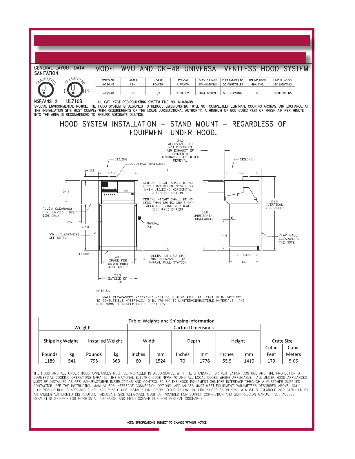
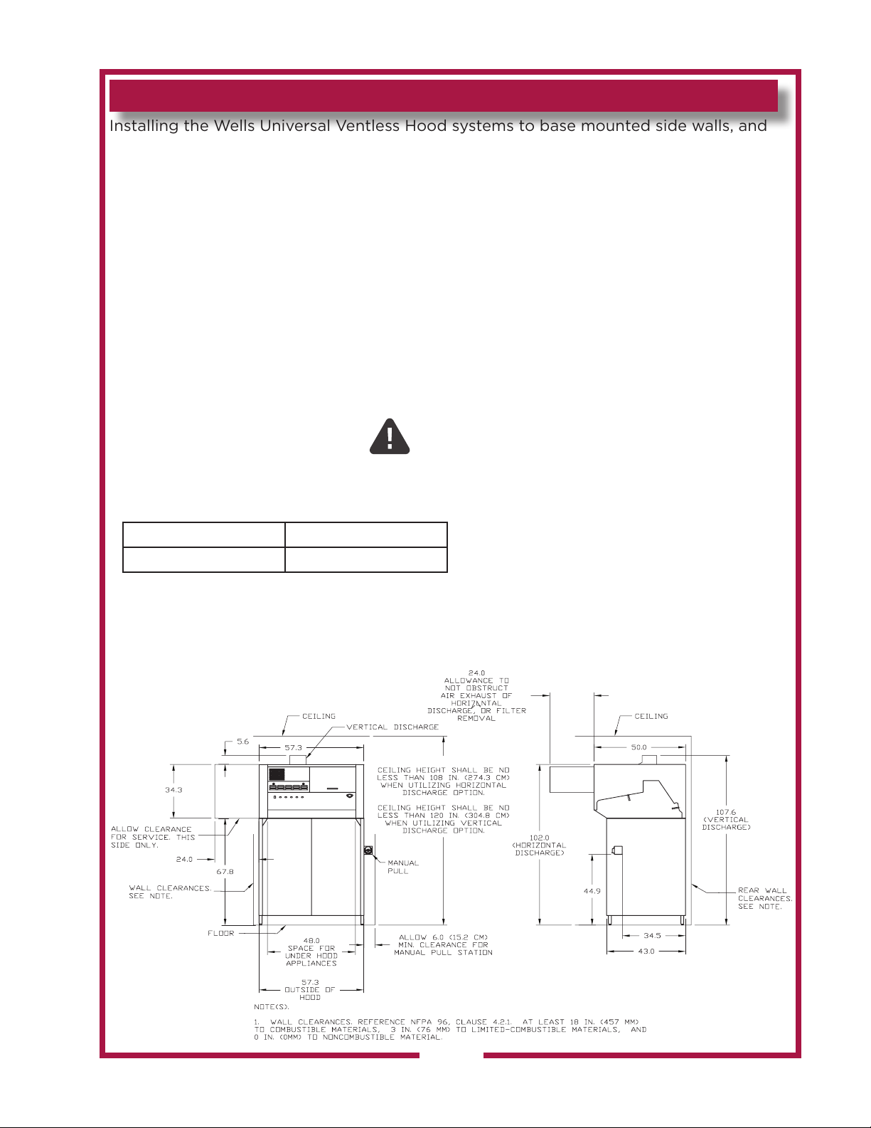
Plan the installation area for the hood. The following diagram includes the required clearances for
the hood installation, this is regardless of the type of hood mount, stand or ceiling mount, and equipment
underneath that is to be used under the hood.
The ceiling height must be 108 in. (274.3 cm) for installation of a unit with front, horizontal discharge, or
120 in. (304.8 cm) for installation of a unit with vertical discharge on 6 [six] inch legs. This requirement
is for both base and ceiling mount installations.
Wall clearances specified per NFPA 96, clause 4.2 must be maintained between the hood and combustible,
limited-combustible, and noncombustible materials. For reference, these clearances are 18 in. (457mm) to
combustible material, 3 in. (76 mm) to limited-combustible material, and 0 in. (0mm) to noncombustible
material.
Allow 24” of access on the service side (left side) of the hood. Check your local juristictional codes for any
additional restrictions or requirements.
Allow 6” of clearance on the right side of the hood for installation of the remote pull station.
!CRITICAL!
If the installation is a ceiling mount, the ceiling structure must be able to support the weight of the hood.
The structural integrity of the ceiling, and the ceiling modifications that are required must be determined by
a structural engineer. This is the responsibility of the installation contractor.
Table: Hood weights.
Model(S) Weight (lb. / kg)
WVU-48 and GK-48 798 lb. (362 kg.)
There are floor mounted bases available and these can be ordered as a separate kit.
The installation will require lifting equipment to raise the hood to the installed height, regardless of base or
ceiling mount.
M522 p/n 2M-Z23068 OpM WVU- Universal Hood
9
Page 12
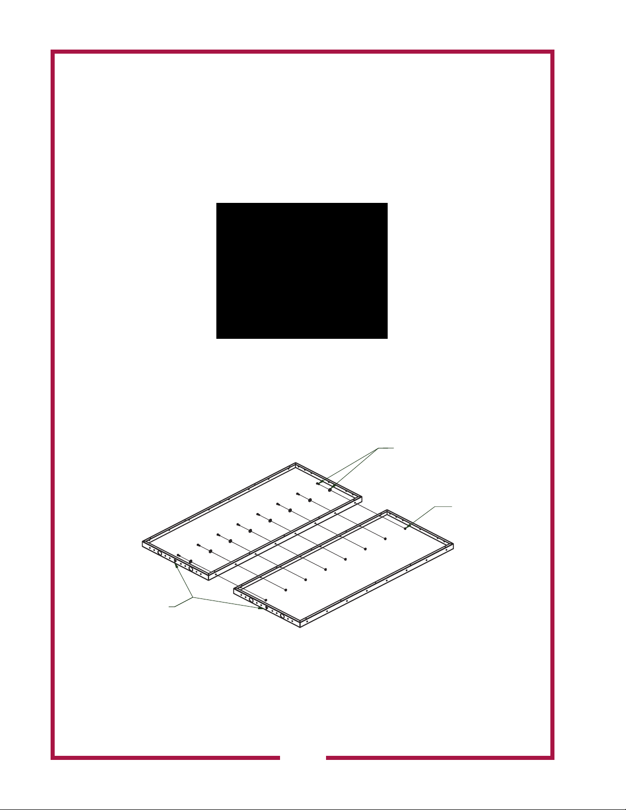
1.1 INSTALLING AND ASSEMBLING BASE MOUNTED HOOD
1/4-20 UNC X .750 HEX HEAD CAP SCREW
A base mounted hood will need to have the base assembled in place prior to raising the
hood and installing it on to the base.
1. Uncrate the hood and all components.
2. Assemble the base in the location that the hood will be located.
3. Locate the required hardware to assemble the base. The hardware required includes
1/4-20 UNC x .75 long Hex Head Cap Screws (bolt), 1/4 Flat Washers, and 1/4-20 UNC
Hex Nuts.
4. Use a flat, smooth, and clean floor surface, with all debris or obsturctions removed
to avoid damage. Align the two rear panels and secure to each other with one bolt, flat
washer, and nut at each hole location (8 places).
REAR PANEL - 2 REQUIRED
OTE. NUMBER 4 FOR BOTH
PANELS ARE ALIGNED).
WITH FLAT WASHER UNDER HEAD
(8 PLACES)
1/4-20 UNC HEX NUT
(8 PLACES)
M522 p/n 2M-Z23068 OpM WVU- Universal Hood
SK2964
10
Page 13
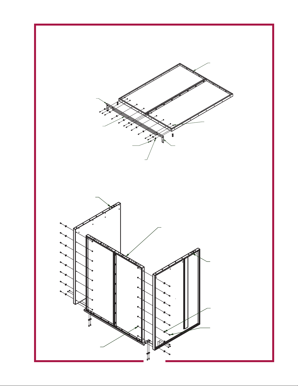
5. Place the base bottom stiener on the bottom and secure with one bolt, flat washer,
ASSEMBLY FROM
.
(12 PLACES)
RIGHT BASE SUPPORT
CREW
and hex nut at each hole location (8 places). Attach the corner stieners on each end and
secure with one bolt, flat washer, and hex nut at each hole location (4 places).
PREVIOUS STEP(S)
NUMBERS ON THIS
SIDE.
CORNER STIFFENER
(NOTICE POSITION OF
FLANGE)
6. Attach the left-side and right-side panels to the rear base panels. Secure with the
bolt, flat washer, and nut at each hole location. 8 on each side plus 4 located at the corner
stieners.
ASSEMBLY (LETTER "R")
BASE STIFFENER
PLATE
1/4-20 X .750 HEX HEAD CAPSCREW
(12 PLACES)
1/4 FLAT WASHER
CORNER STIFFENER
(NOTICE POSITION OF
FLANGE)
ASSEMBLY FROM
PREVIOUS STEP(S).
NUMBERS ON THIS
SIDE.
1/4 X 20 UNC HEX NUT
(12 PLACES)
LEFT BASE SUPPORT
ASSEMBLY (LETTER "L")
M522 p/n 2M-Z23068 OpM WVU- Universal Hood
1/4 X 20 UNC HEX NUT
(20 PLACES)
11
1/4 FLAT WASHER
(20 PLACES)
1/4-20 X .750 HEX HEAD CAPS
(20 PLACES)
Page 14
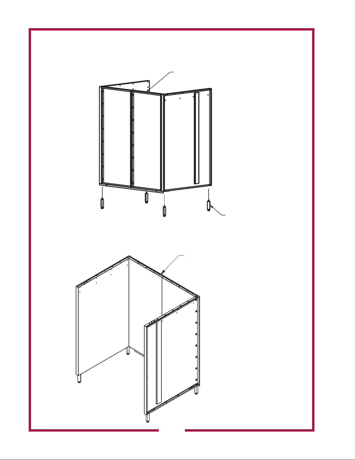
7. Attach the legs to the bottom of the base assembly. Use a level, adjust the legs until
LEGS (4 PL.)
ASSEMBLY FROM
APPLY BEAD OF SILICON
the walls are level both front to back, and side to side. Check level again after installing the
hood.
PREVIOUS STEP(S).
8. The hood is now ready to be placed on the top of the base. Place the base at the final
location desired, and in accordance with all clearance requirements. Apply a bead of silicon
along the top of the panels.
ALONG TOP SURFACE
OF PANELS.
M522 p/n 2M-Z23068 OpM WVU- Universal Hood
12
Page 15
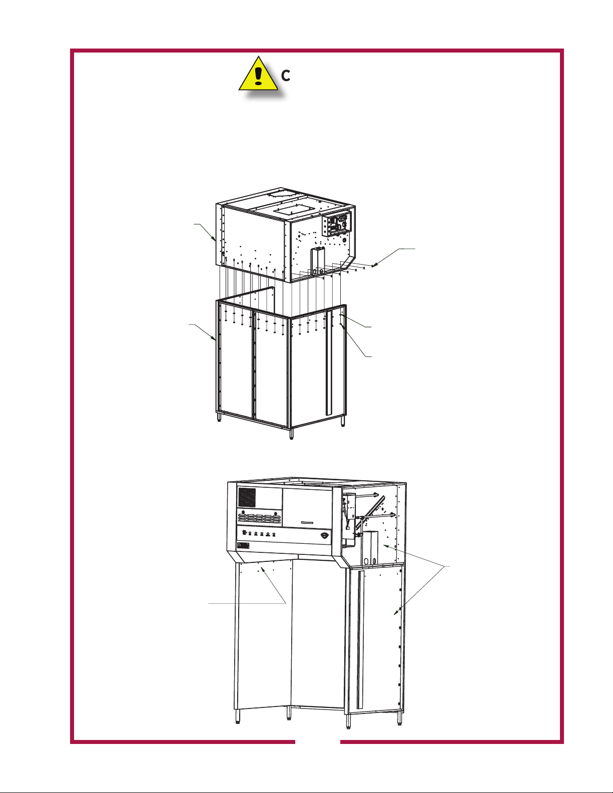
CAUTION
N
.
• The next step places the hood on to the base assembly. The hood needs to be supported
by a supporting device that is acceptable to raise the hood into position.
9. Install the hood directly downward on to the base assembly, ensure the silicon makes an
airtight seal. Secure with the bolt, flat washer, and nut at each hole location.
HOOD. NOTE, THE
OT INSTALLED. THESE WILL
SIDE PANELS ARE
BE INSTALLED LATER.
1/4-20 X .750 HEX HEAD CAPSCREW
(22 PLACES)
ASSEMBLY FROM
PREVIOUS STEP
1/4 FLAT WASHER
(22 PLACES)
1/4 X 20 UNC HEX NUT
(22 PLACES)
The unit is now complete and ready for electrical installation, fire extinguishing system
assembly, equipment installation, and final assembly.
INSTALL SIDE PANELS
AT END OF INSTALLATION
INSIDE BASE DEFLECTORS
CAN BE INSTALLED AT
ANY TIME. SEE SECTION ON
INSTALLATION.
BOTH SIDES.
M522 p/n 2M-Z23068 OpM WVU- Universal Hood
13
Page 16
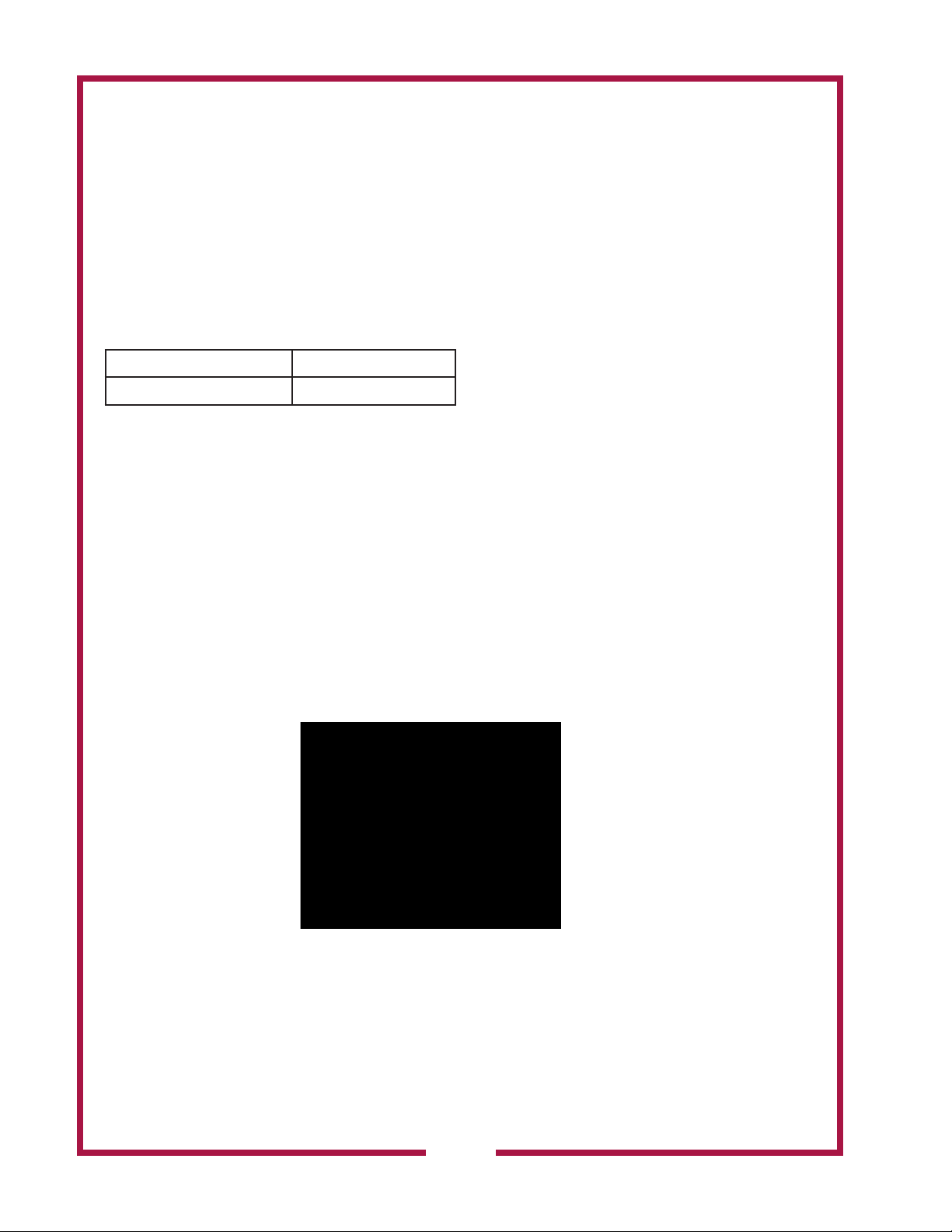
1.2 ASSEMBLING THE CEILING MOUNTED HOOD FOR INSTALLATION TO THE CEILING.
The skirt for the hood will be assembled first and then attached to the hood. Then, the
entire assembly will be mounted to the ceiling.
When the installation is a ceiling mount, the ceiling structure must be able to support
the weight of the hood. The structural integrity of the ceiling, and the ceiling
modifications that are required must be determined by a structural engineer. This is
the responsibility of the installation contractor.
Table: Hood weights.
Model(S) Weight (lb. / kg)
WVU-48 and GK-48 798 lb. (362 kg.)
There are floor mounted bases available and these can be ordered as a separate kit.
The installation will require lifting equipment to raise the hood to the installed height,
regardless of base or ceiling mount.
A ceiling mounted hood will have the skirt assembled in place prior to raising the hood for
installation on the skirt. The entire assembly will be mounted to the ceiling.
1. Uncrate the hood and all components.
2. Assemble the base in the location that the hood will be located.
3. Locate the required hardware to assemble the skirt. The hardware required includes
1/4-20 UNC x .75 long Hex Head Cap Screws (bolt), 1/4 Flat Washers, and 1/4-20 UNC Hex
Nuts.
M522 p/n 2M-Z23068 OpM WVU- Universal Hood
14
Page 17

4. Use a flat, smooth, and clean floor surface, with all debris or obsturctions removed to
avoid damage. Align the two rear panels and secure to each other with one bolt, flat washer,
and nut at each hole location (8 places).
5. Place the base bottom stiener on the bottom and secure with one bolt, flat washer,
and hex nut at each hole location (8 places). Attach the corner stieners on each end and
secure with one bolt, flat washer, and hex nut at each hole location (4 places).
6. Attach the left-side and right-side panels to the rear base panels. Secure with the
bolt, flat washer, and nut at each hole location. 4 on each side plus 4 located at the corner
stieners.
M522 p/n 2M-Z23068 OpM WVU- Universal Hood
15
Page 18

7. The ceiling mount skirt does not have legs. The base has rear flanges that will not
allow it to sit level. Use wood to assist in keeping the flanges/skirts raised, and keep the
assembly level for the remainder of the installation.
8. The ceiling mount hood is now ready to be placed on the top of the skirt. Place the
skirt at the final location desired, and in accordance with all clearance requirements. Apply a
bead of silicon along the top of the panels.
CAUTION
9. Final installation is to be determined by contractor and structural engineer. The
ceiling structure and mounting must be structurally capable to support the hoods weight and
mounting system.
Use ½” diameter threaded rods to hang ceiling mounted hoods. The holes in the
ceiling and structure shall be 9/16” diameter. The following figure is the hole locations to
hang a WVU-48 hood.
16
M522 p/n 2M-Z23068 OpM WVU- Universal Hood
Page 19

The next step places the hood on to the base assembly. The hood needs to be supported by
a supporting device that is acceptable to raise the hood into position.
9. Install the hood on to the base assembly.
The unit is now complete and ready for ceiling installation, electrical installation, fire
extinguishing system assembly, equipment installation, and final assembly.
M522 p/n 2M-Z23068 OpM WVU- Universal Hood
17
Page 20

1.3 CEILING MOUNT DETAIL
Plan out the mounting of the ceiling mount hood. All roof structure requirements and
modifications must be able to hold the ceiling hood weight and the mounting structure. This
is the responsibility of the contractor and structural engineer to insure these requirements.
The mounting is made with 1/2” threaded rods. Drill 9/16” diameter holes in the ceiling and
supporting structure to line up with the threaded holes in the top of the hood. The following
diagrams are the hole patterns to insure wall clearances and to place the hood in the correct
position.
Diagram 1: Ceiling hole pattern, WVU-48 and GK-48
18
M522 p/n 2M-Z23068 OpM WVU- Universal Hood
Page 21

1.3 CEILING MOUNT DETAIL
Plan out the mounting of the ceiling mount hood. All roof structure requirements and
modifications must be able to hold the ceiling hood weight and the mounting structure. This
is the responsibility of the contractor and structural engineer to insure these requirements.
The mounting is made with 1/2” threaded rods. Drill 9/16” diameter holes in the ceiling and
supporting structure to line up with the threaded holes in the top of the hood. The following
diagrams are the hole patterns to insure wall clearances and to place the hood in the correct
position.
Example of hood mounting.
M522 p/n 2M-Z23068 OpM WVU- Universal Hood
19
Page 22
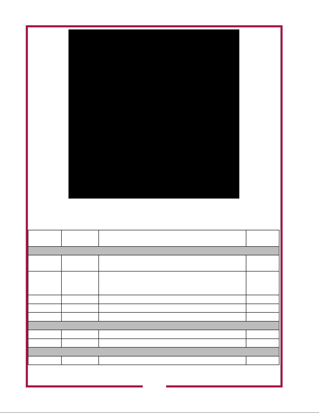
1.4 FIRE EXTINGUISHING SYSTEM INSTALLATION.
At this time, the fire extinguishing system shall be installed and tested by an ANSUL®
authorized distributor.
The GK models require procurement and installation of the following components:
Wells Part
Number
ANSUL®
Part Number
Description Qty Rqd.
48” Models
Actuators and Hoses Required
2O-307966 418691 OEM Regulated Mechanical Actuator Shipping Assembly.
Not Used
Includes Actuator and Regulator, Hose, and Bracket
2O-Z15341 418054 OEM Regulated Electric Release Shipping Assembly
1
(120 VAC). Includes Release Mechanism with Solenoid
and Switch, ¼ in. Hose and Mounting Bracket
2J-Z15444 79007 Hose Assembly 1
2J-Z15426 32335 20 in. Stainless Steel Actuation Hose 2
2J-Z15547 430815 42 in. Stainless Steel Actuation Hose Not Used
Nitrogen Cartridges Required
2O-47099 423429 Cartridge Shipping Assembly (LT-20-R) Not Used
2O-Z14918 423435 Cartridge Shipping Assembly (LT-30-R) 1
ANSULEX Tanks and ANSULEX Required
2O-304433 429864 1.5 Gallon Tank Shipping Assembly 2
M522 p/n 2M-Z23068 OpM WVU- Universal Hood
20
Page 23

Wells Part
Number
2O-47469 79694 1.5 Gallon Container of ANSULEX Low pH Liquid Fire
ANSUL®
Part Number
Description Qty Rqd.
48” Models
2
Suppressant
Nozzles and Nozzle Components Required
2O-302931 439864 Stainless Steel Nozzle Shipping Assembly (1W). Includes
1
one blow-off cap
2O-307481 423572 (25
Swivel Adapter Shipping Assembly 4
in package)
2O-47267 439865 Stainless Steel Nozzle Shipping Assembly (1N). Includes
1
one blow-off cap
2O-Z14574 439843 (25
Nozzle Shipping Assembly (245). 4
in package)
2O-Z17942 439842 (50
in package)
2O-Z20376 439637 (9
in package)
Nozzle Shipping Assembly (230). Includes Nozzles and
Blow-Off Caps
Nozzle Shipping Assembly (1/2N). Includes
Nozzles and Blow-Off Caps
Not Used
Not Used
Manual Pull Station Parts Required
2O-47272 423251 (50
Pulley Elbows Shipping Assembly (Compression End) 1
in package)
N1-Z15506 434525 Flexible Conduit (500 ft.) 6 ft.
2A-47470 26317 Stop Sleeve 2
2K-Z15507 435979 Flexible Conduit Strain Relief 2
2K-Z15508 434347 Flexible Conduit Inserts 2
2O-301164 4596 Oval Press-To-Crimp Sleeves 1
2O-308131 434618 Remote Manual Pull Station 1
2O-47466 79653 or
15821
1/16 in. Stainless Steel Cable. ANSUL part no.
79653 is 500 ft. ANSUL part number 15821 is 50 ft.
14 ft.
1.5 FIRE EXTINGUISHER NOZZLE INSTALLATION
To be compliant with Wells Manufacturing 710B listing, the nozzles shall be installed per the
following diagrams:
Diagram 1. GK-48 Appliance Nozzles
M522 p/n 2M-Z23068 OpM WVU- Universal Hood
21
Page 24

Diagram 2. GK-48 Plenum Nozzle
1.6 MANUAL PULL STATION INSTALLATION
The installation of the manual pull station is similar for all units. The components that are
supplied are in a carton shipped with the unit. The WVU models contain the remote pull
station assembly and the cable readied for installation. The GK models do not contain the
remote pull station or the cable assembly. These components must be procured by the
customer and installed by an ANSUL® authorized distributor.
22
M522 p/n 2M-Z23068 OpM WVU- Universal Hood
Page 25

1.8 INSTALLATION OF THE BASE DEFLECTORS.
e installation of the base deectors is the same regardless if the hood being a base mount or
ceiling mount. e installation of the deectors may be completed at any time.
1. Locate the required hardware and deectors to install onto the units.
2. Install the tinnerman nuts onto the deectors.
3. Install the deectors onto the hood. A 48” base mount is shown.
M522 p/n 2M-Z23068 OpM WVU- Universal Hood
23
Page 26

1.7 SIDE COVER INSTALLATIONS
Install the covers on the side of the hood and base. e le side also has a cover for the electrical
connection box.
24
M522 p/n 2M-Z23068 OpM WVU- Universal Hood
Page 27

1.9 ACCESS TO ELECTRICAL INTERFACE
The access to the terminal block to connect the electrical interface connections is by
removing the cover on the left side panel. See the electrical installation section for the wiring
installation. The .875” diameter knock-out holes are made for ½” electrical box connector
fittings.
2.0 EQUIPMENT INSTALLATIONS
GRIDDLE LIMITATIONS (ELECTRICAL APPLIANCES ONLY)
Summary. Electric griddles up to 36” wide, up to 5.5 kW per linear foot of input power, and
with temperature control up to 450°F (230°C) are acceptable to be used under Wells WVU
and GK model hoods. These must be installed according to the requirements illustrated in
figure 1.
Star-max 515, 524, and 536 models, Ultra-max 724 and 736 models, Toastmaster models
TMGE24 and TMGE36, and Wells models G13, G19, and G23 are all acceptable for use under a
Wells Ventless Hood.
Figure 1. Electric griddle installation parameters (Star-Max 36” griddle
shown under WVU-48SS)
M522 p/n 2M-Z23068 OpM WVU- Universal Hood
25
Page 28

FRYER LIMITATIONS (ELECTRICAL APPLIANCES ONLY)
Summary: Electric fryers with a heated oil pan up to 18” wide, up to 16.9 kW per linear foot
of input power, and with temperature control up to 400°F (200°C) are acceptable to be
used under Wells WVU and GK model hoods. These must be installed according to the
requirements illustrated in figures 2 and 3.
Star-max countertop models 514LL, 301HLF, 515F. 530FF and 530TF, and Wells countertop
models F15, F30, F1725 and LLF14 are all acceptable for use under a Wells Ventless Hood.
Wells floor models WFAE55F and WFEA55FC are all acceptable for use under a Wells
Ventless Hood.
Figure 2. Electric counter top fryer installation
parameters (Star-Max 530TF shown under WVU-48SS)
Figure 3. Electric floor model fryer installation parameters
(Wells WFAE55FC shown under WVU-48SS)
M522 p/n 2M-Z23068 OpM WVU- Universal Hood
26
Page 29
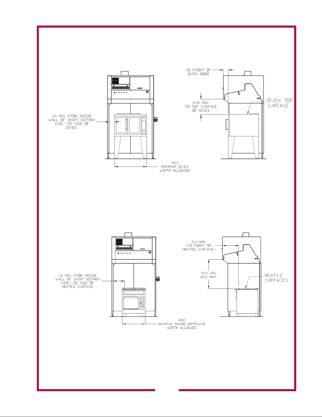
OVEN LIMITATIONS (ELECTRICAL APPLIANCES ONLY)
Summary. Electric ovens up to 48” wide, and temperature control up to 575°F (300°C) are
acceptable to be used under Wells WVU and GK model hoods. These must be installed
according to the requirements illustrated in figures 4.
Figure 4. Electric oven installation parameters (Lang model
ECOH shown under WVU-48SS)
RANGE / HOTPLATE LIMITATIONS (ELECTRICAL APPLIANCES ONLY)
Summary. Electric range tops up to 48” wide and up to 5.5 kW per linear foot of input power
are acceptable to be used under Wells WVU and GK model hoods. These must be installed
according to the requirements illustrated in figures 5.
Figure 5. Electric range/hotplate installation parameters (Lang
model R30S-ATD shown under WVU-48SS)
M522 p/n 2M-Z23068 OpM WVU- Universal Hood
27
Page 30
INSTALLATION
DANGER:
SUFFOCATION HAZARD
Do not attempt to use this
ventilatorwithgas-redunits.
This ventilator will not remove
products of combustion.
Unvented exhaust gasses
can be deadly.
WARNING
SHOCK HAZARD
Electrical connections must
be made by a licensed
electrician.
CAUTION:
FIRE HAZARD
HEALTH HAZARD
All cooking appliances
must be connected to
the cooking appliance
contactor, the control circuit
of which is controlled by the
ventilator.
Note: Shunt trip breakers
are not an authorized
control circuit. All
appliances must be
installed per the under hood
limitations.
ELECTRICAL INSTALLATION
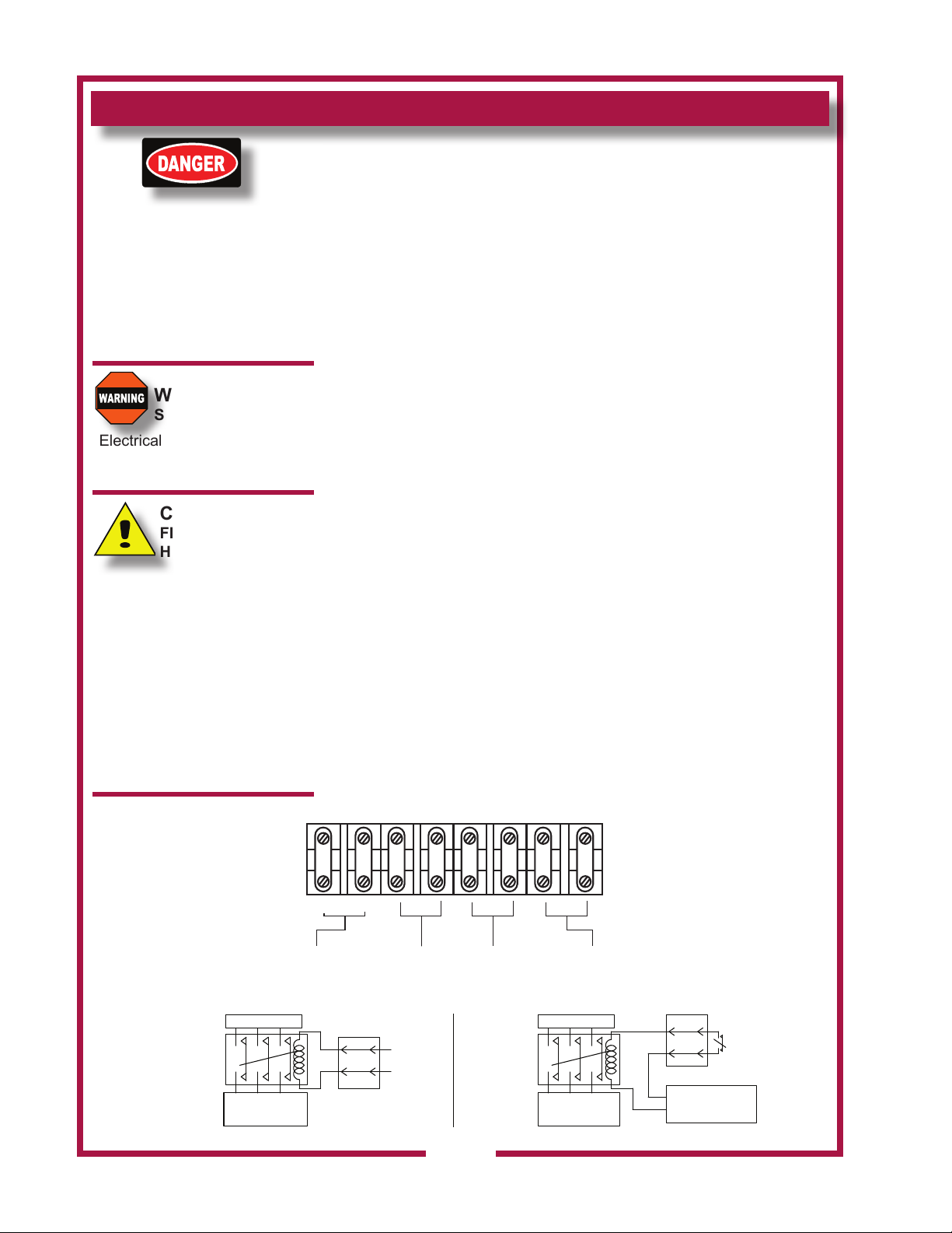
Refer to the nameplate on the ventilator. Verify ELECTRICAL
SERVICE POWER. Voltage and phase must match the nameplate
specications,andavailableelectricalserviceamperagemustmeetor
exceedthelistedamperage.Refertospecicationslistedonpage1of
this manual.
The ground lug of this ventilator must be connected to a suitable
building ground.
Remove the left side panel to access the cooking appliance contactor
and building alarm relay. Remove the appropriate knockout, then wire
the cooking appliance control circuit to the terminal block per Fig below.
NOTE: It is the responsibility of the electrical contractor to provide
suitablewiring,exibleorrigidconduit,contactors,andanappropriate
strain relief.
Electrical Connection
NOTE: The hood requires a single phase (1ph), 208 or 240 volt, 20
amp supply at 60 Hz. When connecting line voltage to the unit’s
terminal block, use a minimum of #12 gage copper wire only, suitable
for 167°F (76°C) ambient temperature.
Appliance Connections
All under hood appliances are required to be interlocked with the hood’s
equipment cut-off circuit, through a customer supplied contactor. Shunt
trip breakers are not authorized. This contactor must be a UL listed,
denitepurposeACresistiveairheatingtype,suitablefortheapplianceload.
Installation and connections shall be in accordance with the National Electric
Code NFPA 70. These connections provide an automatic shutdown of the
appliance when the hood is OFF, or in the event of a malfunction or appliance
re.
Equipment Cutoff Connections
Opt 1: Use TB#3 & TB#4 for 208 or 240 volt control circuit. These contacts will be
de-energized when the hood is OFF or in the event of a malfunction
Opt 2: Use TB#5 & TB#6 as a Normally Closed SPST relay connection for equipment
control circuits with voltages other than 208 or 240 AC. These contacts will be
CUSTOMER
SUPPLIED
CONTACTOR(S)
TB1
TB2
L1 L2
LINE INPUT
208-240VAC
60HZ
TO APPLIANCE
OVER CURRENT
PROTECTED
SUPPLY
EQUIPMENT INTERFACE OPTION 1
TO CUSTOMER
SUPPLIED APPLIANCE
CONTACTOR
(240V CNTR CIRCUIT)
OPTION 1
208/240V
TB3
APPLIANCE
CONTROL
TB4
EQUIPMENT
CUTOFF
TERMINALS
TB3
TB4
TB5
TO CUSTOMER
SUPPLIED
SWITCHING
DEVICE (SPST)
OPTION 2
CUSTOMER
SUPPLIED
CONTACTOR(S)
28
TB6
TB7
TB8
BUILDING
ALARM
INTERFACE
TO APPLIANCE
OVER CURRENT
PROTECTED
SUPPLY
EQUIPMENT INTERFACE OPTION 2
SOURCE CIRCUIT
T3
TB5
TB6
L3
CUSTOMER
SUPPLIED
SPST
SWITCHED
EQUIPMENT
CUTOFF
TERMINALS
IL2376a
M522 p/n 2M-Z23068 OpM WVU- Universal Hood
Page 31
INSTALLATION continued
open when hood is OFF or in the event of a malfunction.
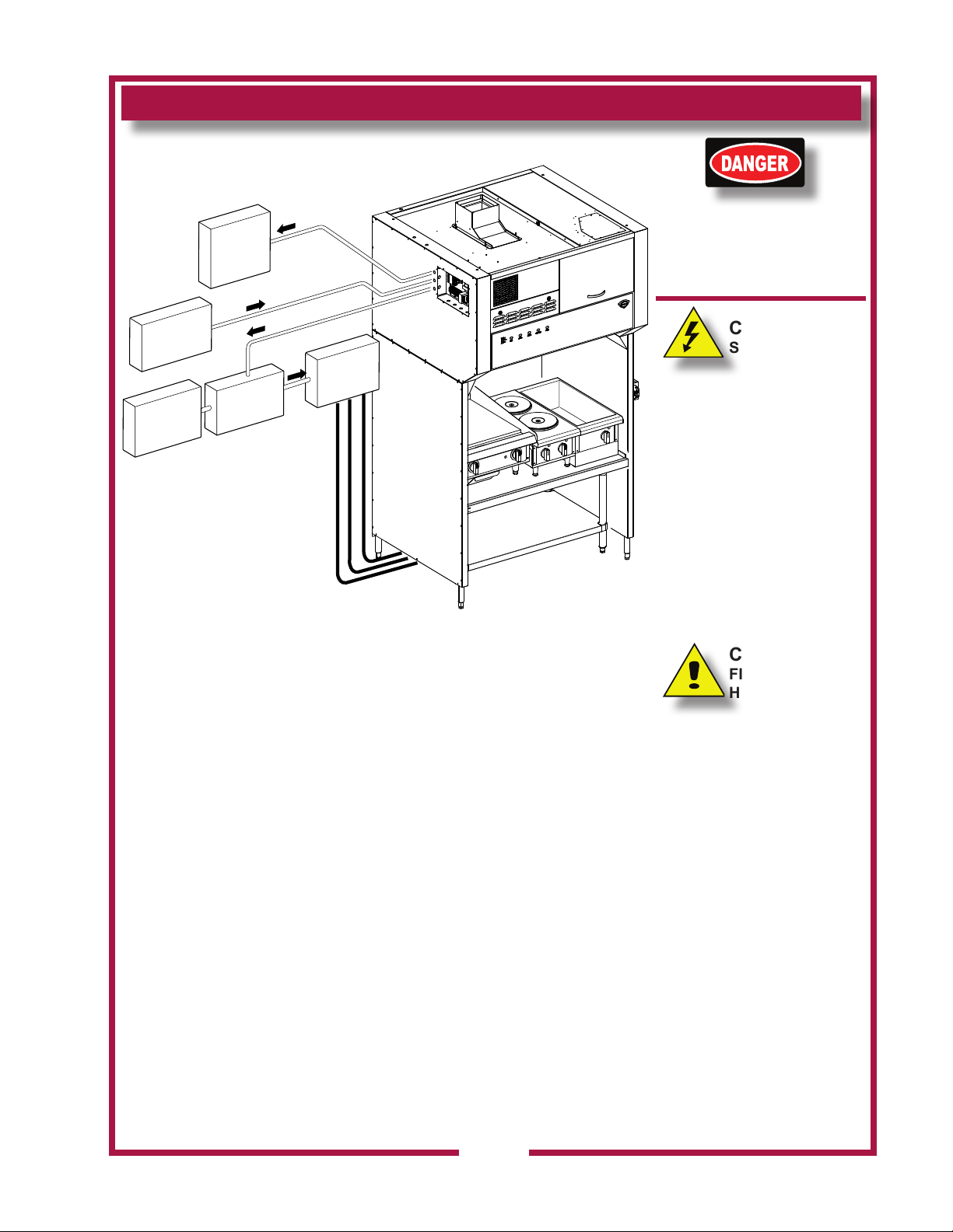
SUPPLY POWER INSTALLATION
FIRE
ALARM
SYSTEM
DANGER:
SHOCK HAZARD
Turn power off to the unit
before removing the side
electrical box cover.
SUPPLY
POWER
TO HOOD
APPLIANCE(S)
POWER
SUPPLY
HOOD
INTERFACE
CONTACTOR(S)
Shunt trip
breakers are
not authorized
POWER
TO
APPLIANCE(S)
CAUTION:
SHOCK HAZARD
The ground lug of this
appliance must be connected
to a suitable building ground.
IMPORTANT:
Contact a licensed electrician
to install and connect electrical
power to the appliance.
IMPORTANT:
Damage due to being
IL2392
connected to the wrong
voltage or phase is NOT
covered by warranty.
CAUTION:
FIRE HAZARD
HEALTH HAZARD
Failure to control cooking
appliances will provide no
protection in the event of a
re,norwillcookingvapors
and odors be contained in
the event of ventilator hood
malfunction.
Any steam or heat exhaust
must be diverted away from
the thermal detectors.
M522 p/n 2M-Z23068 OpM WVU- Universal Hood
29
Page 32

INSTALLATION continued
DANGER
FIRE HAZARD
Fire suppression system
mustbechargedandcertied
by an authorized Ansul®
distributor.
DO NOT attempt to modify or
bypasstheresuppression
system.
Anuncontrolledrecan
cause serious injury or death.
NOTE:
Ansul Deployments are not
covered under warranty.
Technical service needs to
be contacted immediately
and a deployment kit of parts
needs to be replaced before
unit is put back in service. If
theresuppressionsystem
is discharged, a buzzer will
sound continuously. The
unit will remain inoperable
untiltheresuppression
system is serviced, recharged
and reset by an authorized
Ansul® distributor.
Charging of the Ansul®
Fire Suppression system
must be in accordance with
Ansul® Design, Installation,
Recharge and Maintenance
Manual, #418087.
NOTE:
If a REMOTE MANUAL PULL
STATION is installed, moving
the ventilator for any reason
may cause the Ansul®
system to discharge.
IMPORTANT:
Shouldtheresuppression
system discharge: all
nozzles must be replaced,
and all lines thoroughly
cleaned, prior to recharging
thesystem.Residualre
suppression media may
compromisetheowand
dispersionofresuppression
media in any subsequent
activation.
ThealarmrelayisactivatedbytheAnsul®redetectionsystem.Ifthe
installation includes a building alarm system, connect to terminals T7 &
T8 of the terminal block in supply connection box. These terminals are
conguredfromthefactoryfornormallyopenoperation.
The ventilator will operate properly, and the appliance control relay will
be energized, only when:
1. The VENTILATOR POWER SWITCH is “ON”.
2. The Ansul® Fire Suppression System is charged and armed.
3. Allltersareinpositionandserviceable,andtheventilatorairow
systemissatised.
FIRE SUPPRESSION SYSTEM INSTALLATION
EACH 4’ FOOT SECTION OF THE FIRE SUPPRESSION SYSTEM
iscomprisedoftwocontainersofAnsulex®LowpHliquidre
suppression media and a system pressurization canister, plus
associated plumbing. Actuation controls are contained in the Automan
enclosure.
ThehoodissuppliedwithaeldinstalledMANUALPULLSTATION,
which must be set-up at the time of installation by an authorized Ansul®
distributor.
The MANUAL PULL STATION allows for for manual emergency
shutdownofcookingappliancepower,andactuationofthere
suppression system.
Six (WVU48)NOZZLESdispersetheresuppressionmedia.Twoinner
nozzles protect the fan and plenum.
The appliance nozzles are swivel mounted, and must be directed
toward the cooking surface of the installed cooking appliance.
If the ventilator is situated such that the supplied manual pull
station cannot be installed or is not readily accessible, a REMOTE
MANUAL PULL STATION may be required by local codes. Any
such remote manual pull station must be installed by an authorized
Ansul® distributor in accordance with the AUTHORITY HAVING
JURISDICTION.
Theredetectionsystemutilizessix(WVU48) electronic thermal
detectors with an actuation set point of 225°F (107°C) in the upper
hood locations and 275°F (135°C) detectors in the lower wall locations.
The signaling from any of these detection devices will automatically
dischargetheresuppressionmediathroughallnozzles,disablethe
cooking appliances and cause the alarm to sound.
Fire suppression media will form an emulsion designed to both smother
and cool the fuels in/on the cooking appliance.
Ansul® Deployments are not covered under warranty. Technical service
needs to be contacted immediately and a deployment kit of parts needs
to be replaced before unit is put back in service. Any Ansul® media
must be throughly cleaned from every area of the unit before it can be
put back into service.
Wells Manufacturing Technical Service Dept.
Phone: (800) 264-7827 Service Parts Department can supply you with the name
and telephone number of the WELLS authorized service agency nearest you.
30
M522 p/n 2M-Z23068 OpM WVU- Universal Hood
Page 33

INSTALLATION
FIRE SUPPRESSION SYSTEM INSTALLATION (continued)
The MANUAL PULL STATION and any similar REMOTE MANUAL
PULLSTATIONwillactivatetheresuppressionsystemwhenthe
ring on the pull station is pulled to its full extent.
DANGER
BURN HAZARD
Any additional remote pull
station must NOT be installed
on the front of the cooking
appliances,
Dischargeofthere
extinguishing system into hot
grease or oil may cause hot
foam to spill over from the
cooking surface or frypot.
Serious burns and other injuries
can result from contact with hot
oil and from slipping in spilled
oil.
The manual pull station is
installed on the right side (facing
the unit. It may, however, be
relocated to the left side of the
ventilator hood by an authorized
Ansul® agent.
M522 p/n 2M-Z23068 OpM WVU- Universal Hood
31
Page 34
INSTALLATION
NOTE:
The BAFFLE FILTERS,
PRE-FILTERS and FILTER
PACK actuate position
switches when they are
properly positioned. They
must be properly installed
for the under hood cooking
appliance contactor to be
energized.
WARNING
SLIP AND FALL
HAZARD
DO NOT operate any
grease-producing cooking
appliance
(e.g. fryer or griddle) unless
the grease cup is properly
installed.Oilwilldripontooor
creating a slipping hazard.
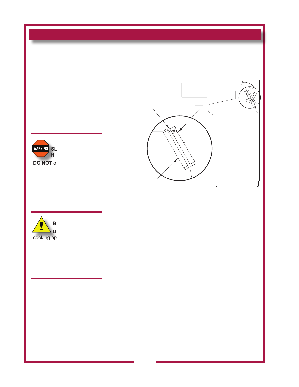
FILTER INSTALLATION
Noteairowdirectionarrowonlterpack.Removeoldlterpack
andslidenewlterpackfullyintotheappropriateslot.Verifythat
theairowarrowpointstowardthefan.
25.9 Min
PREFILTER HOUSING MUST
HOOK IN FLANGE AT TOP.
CHECK TO MAKE SURE YOU
CANNOT PUSH IT BACK
AFTER INSTALLATION
BAFFLE FILTER
PART NO. 2I-Z14670
Clearance
FILTER PACK
PART NO. WL0171
PREFILTER
PART NO. 2I-302579
AIRFLOW
SIDE VIEW
AIRFLOW
IL2377b
CAUTION
BURN HAZARD
DO NOT operate any
cooking appliance unless the
grease cup is installed.
Moisture dripping onto hot
surfaces, oil or grease can
cause splattering.
Bafeltersarereusableandshouldbecleanedatleastweekly.
Changepre-ltersandlterpackasindicatedonthefrontpanel.
Theseltersaredisposableandcannotbereused.Thelterpackis
accessed thru the front service door.
Pre-ltersarelocatedbehindthebafelters,wheninstallingpre-lters
engagetopretainingangepriortoseatingpre-lterhousinginlower
chamber.
BAFFLE FILTER and GREASE CUP INSTALLATION
1. Installbafelterfromfront.Engagethebafelterintheretainer
slot.Pushupuntilthebafelterbottomclearsthelowerlipofthe
retainer,thenlowerthebafelterintothebottomretainer
2. InstallGREASECUPintobracketsbelowthebafelter.
Note: Failure to install the GREASE CUP will allow grease and
moisture from the BAFFLE FILTER to drop into hot cooking surfaces,
creating both a SAFETY HAZARD (hot oil splatter) and a HEALTH
HAZARD (contamination of the cooking surface or cooking oil).
M522 p/n 2M-Z23068 OpM WVU- Universal Hood
32
Page 35
OPERATION
Control Panel
ON
POWER
OFF
NOTE: Cooking appliances must be operated in accordance with the
manufacturer’s instructions.
During normal operation, the illuminated power switch will be the only
light on the control panel that will be ON.
If the CHECK FILTERS light illuminates, check BAFFLE FILTERS,
PREFILTERS, and the FILTER PACK for proper installation.
IftheREPLACEPRE-FILTERSlightilluminates..ReplacethePre-lters.
If the REPLACE FILTER light illuminates, replace the FILTER PACK.
NOTE:theREPLACEFILTERSlightisawarningthatlterpackis
nearing the end of its service life. The ventilator will continue to operate
for a period of time after the REPLACE FILTER LIGHT turns ON to allow
continuedoperationthroughapeakperiod.However,lterpackmustbe
replaced within a short time period or it will clog, disabling the ventilator
and appliances.
IftheSERVICEREQUIREDlightilluminates,thelterpackisrestricted
tothepointofinsufcientairowforproperoperationandtheVentilator
willshutdownuntiltheunderlyingcloggedltersituationhasbeen
corrected.Replacecloggeditemwithafreshltertocorrectthe
condition. Reset the unit by turning VENTILATOR POWER SWITCH to
OFF, then back to ON.
Iftheaircurtainservicerequiredlightsilluminate,thereisinsufcient
airowforproperoperation.CallanauthorizedWellsServiceAgent.
A failure of incoming electric power will cause a shut down of the unit.
Reset the unit by turning VENTILATOR POWER SWITCH to OFF, then
back to ON.
CHECK
FILTERS
REPLACE
PREFILTERS
REPLACE
FILTER PACK
AIR CURTAIN
SERVICE REQUIRED
SERVICE
REQUIRED
CAUTION:
HOT SURFACE
Exposed surfaces can be hot
to the touch and may cause
burns.
CAUTION:
SHOCK HAZARD
DO NOT splash or pour water
or grease onto control panel
or wiring.
IMPORTANT:
The ventilator cannot operate
ifthelterpackisremovedor
clogged.
It is the responsibility of
the store management to
maintainsufcientspares
oflterpackstoavoid
prolonged shutdown of the
ventilatorwhenthislteris
expended.
Filter packs cannot be
cleaned.
Wells Manufacturing assumes
no liability for loss of business
duetolterrelatedshutdown.
Filters that are not genuine
Wells Replacement Parts
may cause your unit to
operate incorrectly and you
will risk the possibility of
voiding your warranty.
Operation Lights
There are three (WVU48) that provide illumination of the working area.
These lights are controlled by the main power switch.
M522 p/n 2M-Z23068 OpM WVU- Universal Hood
33
Page 36
CLEANING INSTRUCTIONS
CAUTION:
HOT SURFACE
Exposed surfaces can be hot
to the touch and may cause
burns. Allow unit to cool
before cleaning.
CAUTION:
SHOCK HAZARD
DO NOT splash or pour water
or grease onto control panel
or wiring.
DANGER
FIRE HAZARD
DO NOT clean heated
surfaces with water, or
Ansul® system may activate
due to sudden rise in
temperature change, causing
theresuppressionsystemto
deploy.
PRECAUTIONS: Disconnect unit from electric power and allow
appliances to cool
Cover frypot to prevent oil contamination
FREQUENCY: Daily
TOOLS: Mild detergent, clean non-abrasive towels, 3M Scotch
brite for griddles
NOTE: Ventilator section to be cleaned in conjunction with cooking
appliance. Refer to appliance user instructions for cleaning procedure.
DO NOT use water on any heated surface during cleaning.
1. TURN HOOD POWER SWITCH TO OFF.
Cover cooking appliance to prevent oil contamination.
2. Remove BAFFLE FILTERS and GREASE CUP(s).
3. Empty GREASE CUP(s) into an appropriate grease collection receptacle.
4. Clean BAFFLE FILTERS and GREASE CUP(s) in a sink or dishwasher
using mild detergent and warm water.
5. Dry components with a clean non-abrasive cloth. Reinstall BAFFLE
FILTERS and GREASE CUP(s) in ventilator.
6. Wipe exterior of ventilator with a clean cloth moistened with warm water
and mild detergent. Rinse by wiping with a clean cloth moistened with
warm water.
7. Uncover the cooking appliance and reconnect unit to electric power.
Procedure is complete
34
M522 p/n 2M-Z23068 OpM WVU- Universal Hood
Page 37
CLEANING INSTRUCTIONS
PRECAUTIONS: Disconnect unit from electric power and allow
appliances to cool
Cover cooking surfaces and frypots to prevent
contamination.
FREQUENCY: Monthly
TOOLS: Mild detergent, clean non-abrasive towels, 3M Scotch
brite for griddles
NOTE: Ventilator section to be cleaned in conjunction with cooking
appliance. Refer to appliance user instructions for cleaning procedure.
DO NOT use water on any heated surface during cleaning.
1. TURN HOOD POWER SWITCH TO OFF.
Cover cooking applaince to prevent oil contamination.
2. Remove BAFFLE FILTERS, GREASE CUP(s), and all FILTER PACK(s).
3. Wipe interior of ventilator with a clean cloth moistened with warm water and
mild detergent. Rinse by wiping with a clean cloth moistened with
warm water. DO NOT clean by spraying.
4. Dry ventilator thoroughly with a clean non-abrasive cloth.
Reinstall all FILTERS, BAFFLE FILTERS, GREASE CUP(s).
5. Uncover the cooking appliance and reconnect unit to electric power.
Procedure is complete
CAUTION:
HOT SURFACE
Exposed surfaces can be hot
to the touch and may cause
burns. Allow unit to cool
before cleaning.
CAUTION:
SHOCK HAZARD
DO NOT splash or pour water
or grease onto control panel
or wiring.
DANGER
FIRE HAZARD
DO NOT clean heated
surfaces with water, or
Ansul® system may activate
due to sudden rise in
temperature change, causing
theresuppressionsystemto
deploy.
IMPORTANT:
DO NOT wash FILTER
PACK.Washingtheselters
will clog them, and cause
installed cooking appliance
to be disabled.
M522 p/n 2M-Z23068 OpM WVU- Universal Hood
IMPORTANT:
DO NOT clean interior of
ventilator by spraying.
Spraying can contaminate the
cooking appliance, and may
cause internal damage to the
ventilator blower, operation
proongsystemand/orre
suppression system.
Clean by wiping only.
35
Page 38
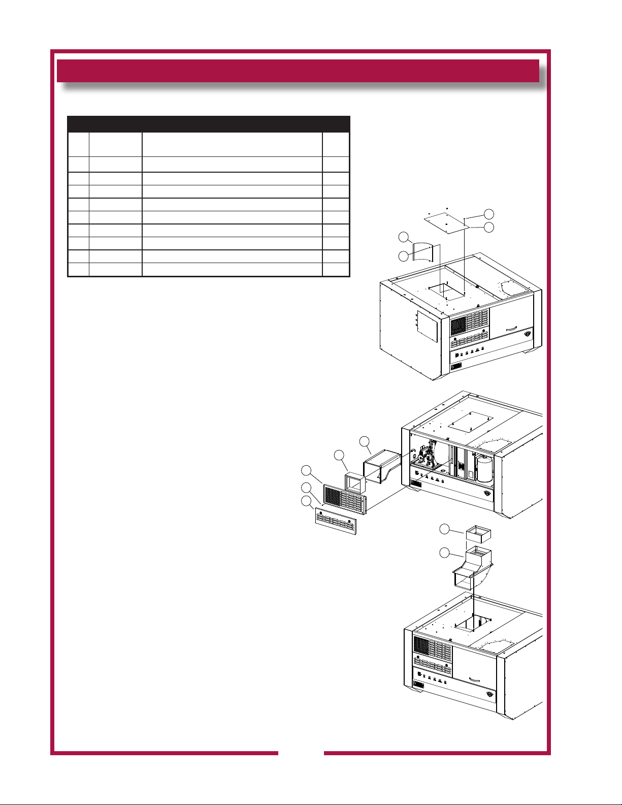
MAINTENANCE: DISCHARGE DIRECTION CHANGE
IL3025
Procedure for changing the discharge on a WVU-48 / GK-48
PARTS LIST
Fig
Part No Description Qty
No
1 2C-35487 SCREW 8-32 X 5/16 PH TR HD AR
2 2C-6517 1/4-20 FLANGED HEX SHAKEPROOF LOCK NUT AR
3 2V-307913 DAMPER FIRE 8X9 1
4 N1-WL0167 ACCESS DOOR ASSY. ELEC COMPARTMENT 1
5 N1-WL0172 FRONT DUCTWORK ASSEMBLY 1
6 N1-WL0244 TOP DISCHARGE SCOOP ASSEMBLY 1
7 N1-Z14097 FRONT DISCHARGE VENT PANEL 1
8 N1-Z14100 DISCHARGE CURVE 1
9 N1-Z14139 BLOCK-OFF PLATE, TOP DISCHARGE 1
Horizontal to Vertical: (min 120” ceiling height)
1. Remove the Front Access Door (Item 4) by turning
the slotted screws ¼ turn and lift out the panel.
2. Remove the Front Discharge Vent Panel (Item 7) by
removing the mounting screws.
3. Remove the damper (Item 3).
4. Re-install the Front Access Door and Front
Discharge Vent Panel.
5. Remove the Top Discharge Block-Off plate (item 9)
by removing the four mounting nuts.
6. Remove the Discharge Curve (Item 8) by removing
the two 8-32 screws (Item 1) securing the curve and
slide the curve out of the bracket.
7. Install the Vertical discharge assembly (Item 6) and
secure with four ¼-20 nuts.
8. Install the damper (Item 3) into the top of the Vertical
discharge assembly (Item 6).
Vertical to Horizontal: (min 108” ceiling height)
1. Remove the damper (Item 3) from the vertical
discharge housing (Item 6).
2. Remove the four nuts that secure the Vertical
discharge housing (Item 6) to the top panel of the
hood.
3. Remove the vertical discharge housing.
4. Insert the discharge curve (Item 8) into the duct as
shown. Slide one end of the curve into the bracket
located on the rear wall of the duct and secure the
front end of the curve with two 8-32 x 5/16 screws
(Item 1).
5. Install the block-off plate (Item 9) and secure with
four ½-20 nuts.
6. Remove the Front discharge vent panel (Item 7) and
access door (Item 4).
7. Install the damper (Item 3) into the front ductwork
assembly (Item 5).
a. Note the required orientation of the damper as noted
on the damper.
8. Re-install the front discharge vent panel and access
door.
7
1
4
36
3
2
9
8
1
5
3
6
M522 p/n 2M-Z23068 OpM WVU- Universal Hood
Page 39

REQUIRED MAINTENANCE
IMPORTANT:
Per NFPS 96, a signed and
dated VENTILATOR HOOD
MAINTENANCE LOG
must be maintained on the
premises, and be made
available for inspection by the
authority having jurisdiction
upon request.
IMPORTANT:
Shouldtheresuppression
system discharge, contact
the technical service team:
(800)-264-7827 All lines
and nozzles must be
thoroughly cleaned prior
to recharging the system.
Ansul Deployments are not
covered under warranty.
technical service needs to be
contacted immediately and a
deployment kit of parts needs
to be replaced before unit
is put back in service. WSWL0964 Deplymnt kit, WVU/
GK -48
Be sure to note such cleaning
on the hood maintenance log.
Residualresuppression
media may compromise the
owanddispersionofre
suppression media in any
subsequent activation.
USE AND MAINTENANCE SHALL BE IN ACCORDANCE WITH THE
STANDARD FOR VENTILATION CONTROL AND FIRE PROTECTION
OF COMMERIAL COOKING OPERATIONS, N.F.P.A. 96 (current
edition).
3-MONTH MAINTENANCE:
Thoroughly clean entire HOOD PLENUM and BLOWER section.
6-MONTH MAINTENANCE:
Inspection and testing of total operation including FIRE DAMPER and
allSAFETYINTERLOCKSshallbeperformedbyqualiedservice
personnel.
All FIRE SUPPRESION SYSTEM actuation components including
MANUAL PULL STATION and any REMOTE MANUAL PULL STATION
must be inspected for proper operation in accordance with the
maintenance schedule published in
INSTALLATION, RECHARGE AND MAINTENANCE MANUAL (418087).
ANNUAL (12-MONTH) MAINTENANCE:
NOZZLES and MANUAL PULL STATION must be cleaned in
accordance with
RECHARGE AND MAINTENANCE MANUAL (418087).
12-YEAR MAINTENANCE:
The FIRE SUPRESSION AGENT TANK must be HYDROSTATICALLY
TESTED, and the FIRE EXTINGUISHING AGENT must be REPLACED
in accordance with the maintenance schedule published in ANSUL®
R-102 SYSTEM (STANDARD UL 300 LISTED). This maintenance to be
performedbyqualiedAnsul®servicepersonnelonly.
ANSUL® R-102 SYSYTEM DESIGN, INSTALLATION,
ANSUL® R-102 SYSTEM DESIGN,
M522 p/n 2M-Z23068 OpM WVU- Universal Hood
37
Page 40
WELLS BLOOMFIELD, LLC
VENTILATOR HOOD OWNERS MONTHLY INSPECTION LOG
IL2144
OPERATION AGENT DATE
Extinguishing system components:
In proper place and (visually in
good order
Manual pull station actuators for fire
suppression system are obstructed
The maintenance log is in place
and up to date
No obvious physical damage or condition
Inspection shall be conducted on a monthly basis in accordance with
the manufacturer’s Operation Manual. At a minimum, this inspection
shall include verification of the following:
exists that might prevent operation of the
The nozzle blow-off caps are in place
fire suppression system
and in good condition
38
The hood, duct and protection cooking
appliance have not been replaced,
modified or relocated
Clean plenum GREASE BAFFLE and
BLOWER (max. interval: 3 months)
Change PRE-FILTER and FILTER PACK
(as required)
M522 p/n 2M-Z16247 OpM WVU- Universal Hood
Page 41

WELLS BLOOMFIELD, LLC
VENTILATOR HOOD MAINTENANCE LOG
IL2378a
OPERATION AGENT / DATE
M522 p/n 2M-Z16247 OpM WVU- Universal Hood
Clean and inspect discharge nozzle in plenum BEFORE filters
This MAINTENANCE LOG is to be performed and completed by a trained technician who has
completed the instruction necessary to perform the maintenance and recharge service.
MAX. interval: 6 months
Clean and inspect discharge nozzle in plenum AFTER filters
MAX. interval: 6 months
Log TEMP
Replace fire damper fusible link:
Inspect fire suppression detectors, all releasing devices for
actuation, fire suppressant tank liquid level
Max interval: 6 months
(discharge of fire suppressant not a part of this test)
Inspect fire suppression hoses, plumbing and tank for
obstructions and any condition such as, but not limited to,
corrosion and pitting.
Max interval: 6 months
Inspect and test all filter interlocks
Max. interval: 6 months
rated @ 212ºF
Log mfg DATE
Stamp
Max interval: 12 months
39
THIS MAINTENANCE LOG MUST BE KEPT IN A PROTECTIVE COVER PERMANENTLY ATTACHED TO THE APPLIANCE
Log all repairs and recommendations on reverse side. Any repairs, other than replacement of factory authorized parts, to the fire suppression plumbing system must be
subject to hydrostatic pressure testing.
Page 42
ANSUL
ANSUL INCORPORATED
MATERIAL SAFETY DATA SHEET
MARINETTE, WI 54143-2542
®
Manufacturer’s
Name:
Address:
Prepared By:
ANSUL INCORPORATED
One Stanton Street, Marinette, WI 54143-2542
Safety and Health Departm ent
SECTION 1 - IDENTITY
Comm on Name (Used on Label):
(Trade Name and Synonyms)
Chemical
Name:
Formula:
N/A T his is a M ixtu re
N/A
ANSULEX Low pH Liquid Fire S uppressant
SECTION 2 - INGREDIENTS
PART A - HAZARDOUS INGREDIENTS
Principal Hazardous Component(s) (chemical and common name(s)):
None
ANSULEX Low pH
QUICK IDENTIFIER (In Plant Common N ame)
Em ergency
Telephone No.:
Other Information
Ca lls:
Date Prepared:
CAS No.:
W t.%
Chemical
Fa mily :
CAS No.
CHEMTREC
(800) 424-9300 or (703) 527-3887
(715) 735-7411
February 1, 1999
N/A
M ixture
ACGIH TLV
Acute Toxicity D ata
N/A N/A N/A N/A
PART B - OTHER INGREDIENTS
Other Component(s) (chemical and common name(s)):
Proprietary Mixture of Organic and Inorganic Salts
Phosphoric Acid 0.2
ED TA
Yellow-Green Fluorescent Dye 0.011
Water
W t.%
48.0 - 50.0
0.6 5
Approx. 50.0
CAS No.
N/A
7664-38-2
64--0 2-8
518-47-8
7732-18-5
ACGIH TLV
N/E
N/E
N/E
N/E
N/E
SECTION 3 - PHYSICAL AND CHEMICAL CHARACTERISTICS (Fire and Explosion Data)
Bo iling
Point:
Percent Volatile
by Volume (%):
Solubility
in Water:
Appearance
and Odor:
Flash Point:
Special Fire
Fighting Procedures:
Unusual Fire and
Explosion Hazards:
113 ºC
Approx. 50.0
Vapor Density:
(Air = 1):
1.0 3
100%
Fluorescent Yellow Colored Liquid, Mild Odor
None to boiling
Flammable Limits
in Air % by Volume:
N/A
NONE - THIS IS AN EXTINGUISHING AGENT
None
Specific
Gravity (H O =1):
2
Evaporation Rate:
(Butyl Acetate=1):
Rea ctivity in
Wa ter:
Extinguisher
Media:
1.3 3
Approx. 0.005
Mild exothermic reaction
N/A N/A
Vapor Pressure
(mm Hg):
Auto-Ignition
Temperature:
SECTION 4 - PHYSICAL HAZARDS
Stability:
Incompatibility
(Materials to Avoid):
Hazardous
Decomposition Products:
Hazardous
Polymerization:
W ill Not Occ ur
Unstable
Stable
Reactive Metals, ClF , electrically energized equipment, any m aterial reactive with water.
Not established, acrid fumes.
May O ccur
Conditions
to Avoid:
Conditions
to Avoid:
N/A
3
N/A
Acute Toxicity D ata
NDA
NDA
NDA
Ora l LD (rat)
6800 mg/kg
NDA
Not Determined
50
40
M522 p/n 2M-Z16247 OpM WVU- Universal Hood
Page 43
SECTION 5 - HEALTH HAZARDS
ANSULEX Low pH (continued)
Threshold
503 p/n 2M-304989 Owners Manual WVF-886 Ventless Fryer
Limit Value:
Routes of Entry:
Eye Contact:
Skin Contact:
Inhalation:
Ingestion:
Signs and
Sym ptoms:
Medical Conditions Generally
Aggravated by Exposure:
Chemical Listed as
Carcinogen or Potential:
SECTION 6 - EMERGENCY AND FIRST AID PROCEDURES
Eye Contact:
Skin Contact:
Inhalation:
Ingestion:
SECTION 7 - SPECIAL PROTECTION INFORMATION
Respiratory Protection
(Specify Type):
Ventilation:
Pro tective
Othe r Protectiv e
Clothing or Equipment:
Gloves:
None Established
Irritant
Irritant
Not an expected route of entry. Can be irritating to mucous membranes.
Irritating to mucous membranes. Acute Oral LD (Sprague-Dawley rats) 825.5mg/kg.
Acute Exposure: Material irritates skin, eyes, and mucous membranes.
Chronic Exposure: None known.
50
None known.
National Toxicology
Program:
Flush and irrigate with water for 15 minutes while holding eyelids open.
If irritation persists, seek medical attention.
Yes
No
I.A.R .C
Monographs:
Yes
No
OSHA
Yes
No
Wash thoroughly with soap and water. If irritation persists, seek medical attention.
Fresh air if symptoms occur. If irritation persists, seek medical attention.
Dilute by drinking large quantities of water.
N/A
Local
Exhaust:
N/A N /A
Rubber gloves for spill/leak
Mechanical
(General):
Eye
Protection:
Chemical goggles recomm ended during
spill/leak procedures.
Eye wash and safety showers are good safety practice.
SECTION 8 - SPECIAL PRECAUTIONS AND SPILL/LEAK PROCEDURES
Precautions to be taken
in Handling and Storage:
Other
Precautions:
Steps to be taken in Case
Material is Released or Spilled:
Waste Disposal
Methods:
Store in original container. Keep tightly closed. Keep separate from acid.
See incom patibility information in Section 4.
Stop leaks. Contain spills. Remove as much as possible. Place in closed container for proper disposal
Wash spill area with large amounts of water to remove traces and neutralize.
Dispose of in compliance with local, state and federal regulations.
HAZARDOUS MATERIAL IDENTIFICATION SYSTEM
HAZARD I NDEX
4 SEVERE HAZARD 0 HEALTH
3 SERIOUS HAZARD
2 MODER ATE HAZARD 0 FLAMMABILITY
1 SLIGHT HAZ ARD
0 MINIMAL HAZARD 0 REACTIVITY
N/A = Not Applicable NDA = No Data Available N/E = Not Established
ANSUL and ANSULEX are registered trademarks.
Internet Address: http://www.ansul.com
ANSUL INCORP ORATED, ONE STANTON STRE ET, MARINETTE , WI 54143-2542 Form No. F-90160-6 ©1999 Ansul Incorporated
M522 p/n 2M-Z16247 OpM WVU- Universal Hood
41
Page 44
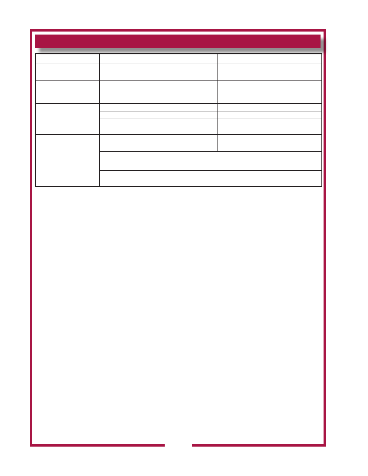
TROUBLESHOOTING SUGGESTIONS
Problem Possible Cause Suggested Remedy
Unit will not operate (no
indicators lights lit)
Unit will not operate
(buzzer sounds)
Disconnected from electric power
Fire suppression system not set
CHECK FILTER light lit Filter pack, Pre-lter or bafe lter not in position Properly install lters
Filter nearing end of service life Arrange to replace lters in a timely manner
REPLACE FILTER light lit
Filter pack plugged Replace lter pack
Fire damper in exhaust collar has closed
One or more vacuum sensing lines or ports
plugged, or sensing line dislodged.
SERVICE REQUIRED
light lit (cooking appliance
not operating)
NOTE: If, after 20 seconds, there is insufcient airow for proper operation, SERVICE REQUIRED
light will illuminate and under-hood appliance (s) will be de-energized.
Press VENTILATOR POWER SWITCH to OFF, then back to ON to reset system.
Reconnect to electric power
Reset circuit breaker for unit
Contact an authorized Ansul®
distributor for repairs
Contact an authorized Wells service
agent for repairs
Contact an authorized Wells service
agent for repairs
NOTE:
FILTERS are the only user serviceable components in this ventilator hood system. For all problems that cannot be remedied by
servicingthelters,contact:
Ventilator section - authorized Wells service agency
Fire suppression system - authorized Ansul® distributor
Ansul Deployments are not covered under warranty. Technical service needs to be contacted immediately and a deployment kit of
parts needs to be replaced before unit is put back in service. WS-WL0964 DEPLYMNT KIT, WVU-48
IMPORTANT:
ContactANSUL®forresuppressionsysteminstallation,set-upandservice:
Ansul Incorporated 1-800-TO-ANSUL (1-800-862-6785)
One Station Street
Marinette, WI 54143-2542 website http;//www.ansul.com
IMPORTANT:
PartsusedintheAnsul®resuppressionsystemarenotserviceablebytheowner/operator.
Proceduresforservicingresuppressionequipmentaredescribedin:
ANSUL® R-102 SYSTEM DESIGN, INSTALLATION, RECHARGE AND MAINTENANCE MANUAL
(418087, current edition)
NOTE:
ANSUL® Manual 418087 is intended for use by authorized Ansul® service personnel only.
42
M522 p/n 2M-Z23068 OpM WVU- Universal Hood
Page 45
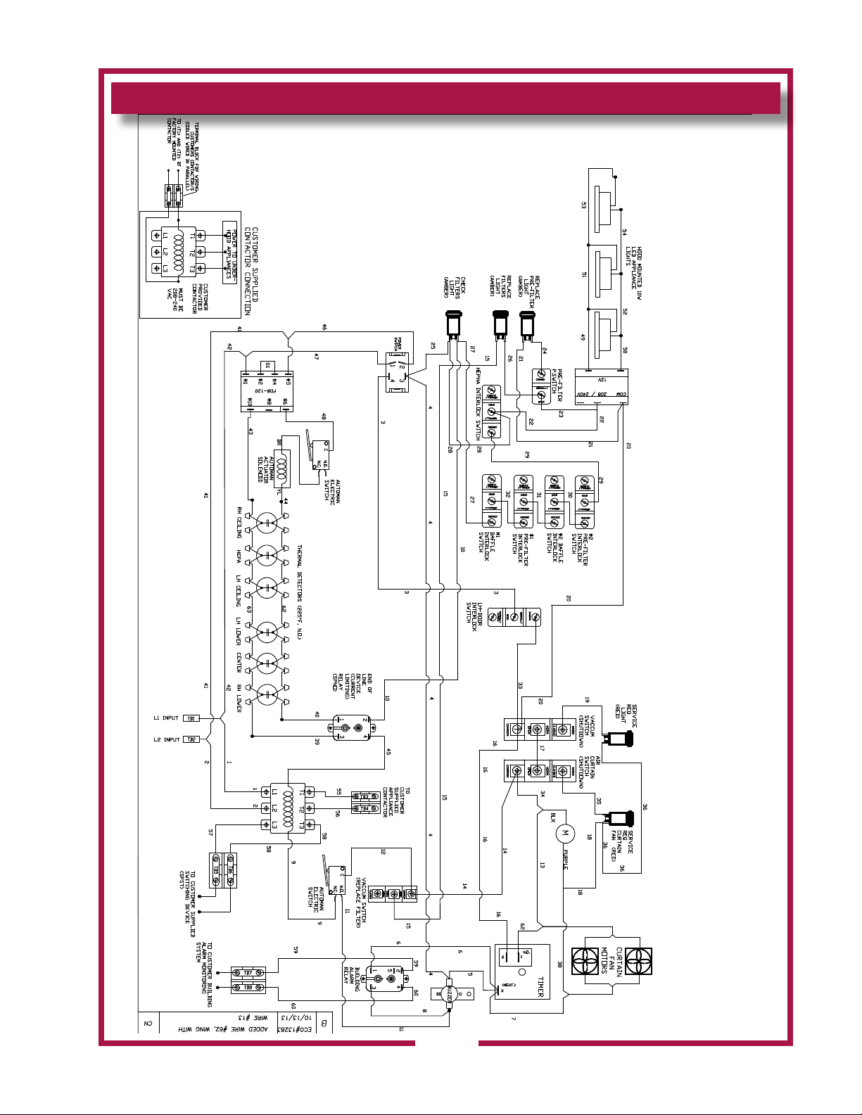
WIRING DIAGRAM
M522 p/n 2M-Z23068 OpM WVU- Universal Hood
43
Page 46
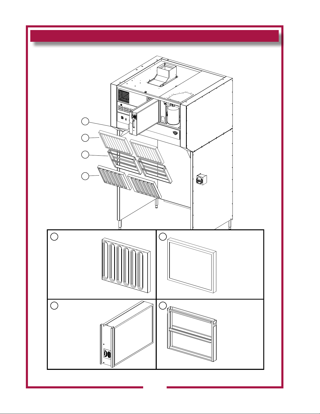
EXPLODED VIEW & PARTS LIST
Filter Maintenance
3
2
4
1
1
Baffle Filter: 16” x 20”
Part No: 2I-Z14670
3 4
Filter Pack
Part No: N1-WL0171
Model: WVU48 Filter Assy
2
Pre-Filter Hood
Part No: 2I-Z16258
Pre-Filter Cage
Part No: M3-WL0230
M522 p/n 2M-Z23068 OpM WVU- Universal Hood
SK2553 Rev. D , 10/20/2015
44
Page 47
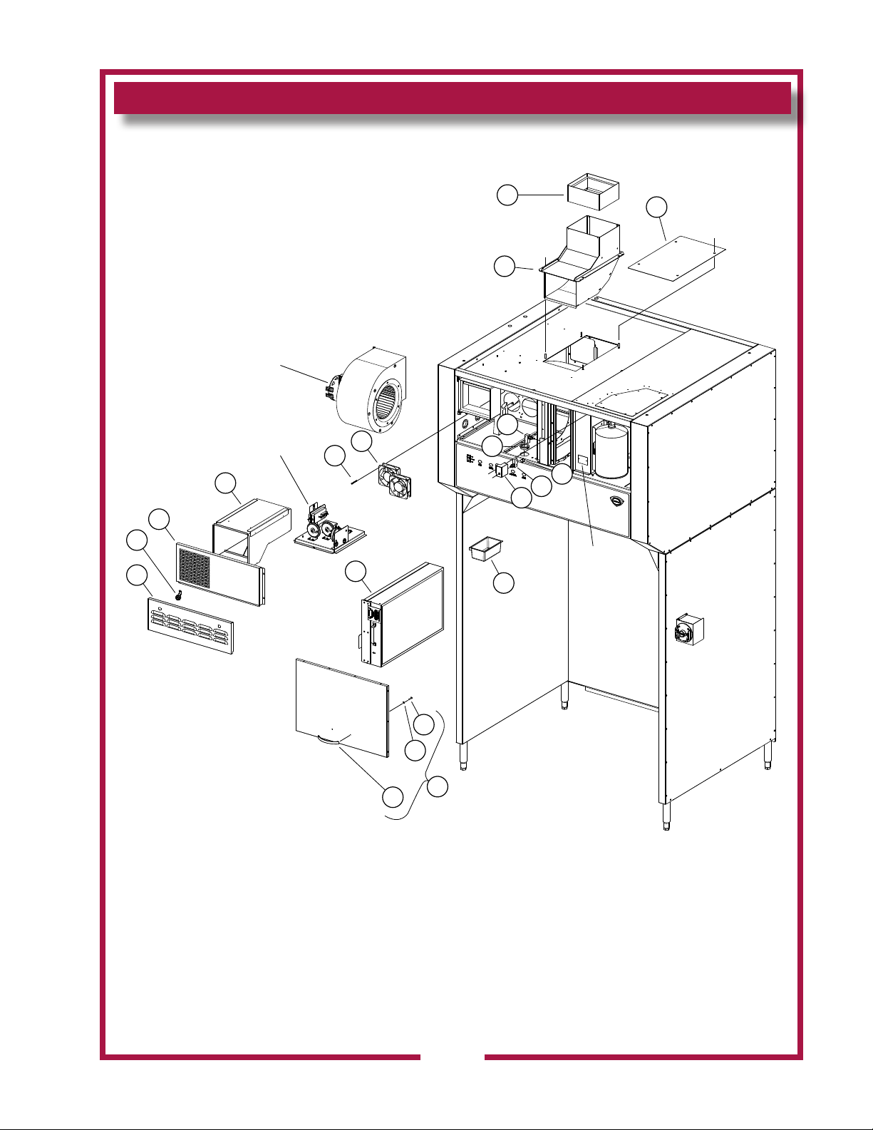
EXPLODED VIEW
Universal Hood Internal Control
12
13
11
See Detail A
See Detail
10
1
2
4
B
8
9
14
5
6
4
7
Nameplate
19
3
Model: WVU48 Universal Hood Internal Control
M522 p/n 2M-Z23068 OpM WVU- Universal Hood
16
18
17
15
SK2554 Rev. A 2/13/2015
45
Page 48
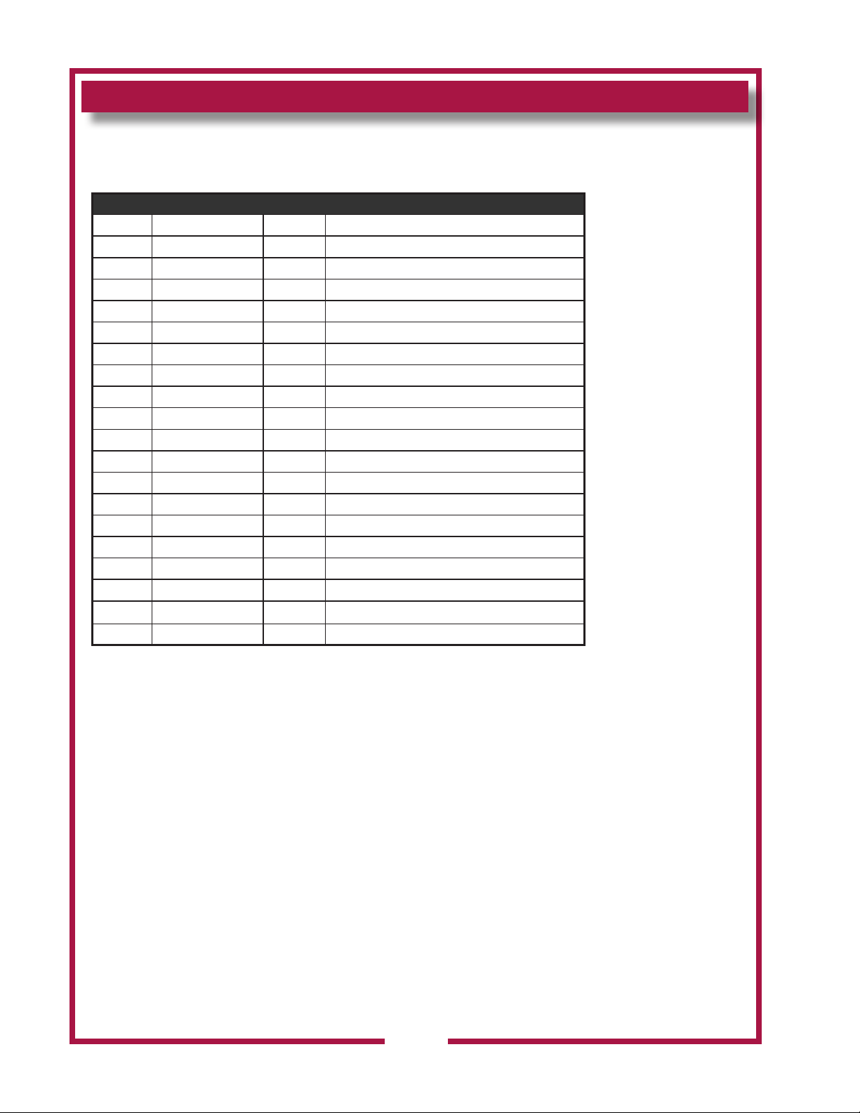
PARTS LIST
Universal Hood Internal Control
Internal Control Assy
Fig No. Part No WVU48 Description
1 2V-307913 1 DAMPER FIRE 8X9 WVU
2 N1-WL0244 1 TOP DISCHARGE SCOOP ASSY.
3 N1-Z14139 1 BLOCK-OFF PLATE, TOP DISCHARGE
4 2E-300407 6 SWITCH MANUAL ADVANCE ROT
5 2K-Y8571 3 BUSHING SNAP 2 1/8
6 2K-Y1139 1 BUSHING HEYCO SB500-6
7 N1-Z14484 1 MOUNTING BRACKET, DOOR
8 2U-200577 2 MOTOR, FAN 240V, HI-OUTPU
9 2C-45201 4 SCREW 8-32X2 PH PAN HD MS
10 N1-WL0172 1 DUCTWORK ASSEMBLY
11 N1-Z14097 1 FRONT DISCHARGE VENTPANEL
12 2R-Z14532 2 CAM LATCH, SLOTTED
13 N1-Z14087 1 ACCESS DOOR, ELECT
14 N1-WL0171 1 FILTER HEPA/CARBON PACK
15 N1-WL0170 1 DOOR ASSY,FRONT ANSUL
16 2R-Z14429 1 HANDLE, 5”
17 2C-1810 2 WASHER 3/16 BURR STL NP
18 Included with #15 2
19 2D-Z14672 1 GREASE CUP
46
M522 p/n 2M-Z23068 OpM WVU- Universal Hood
Page 49
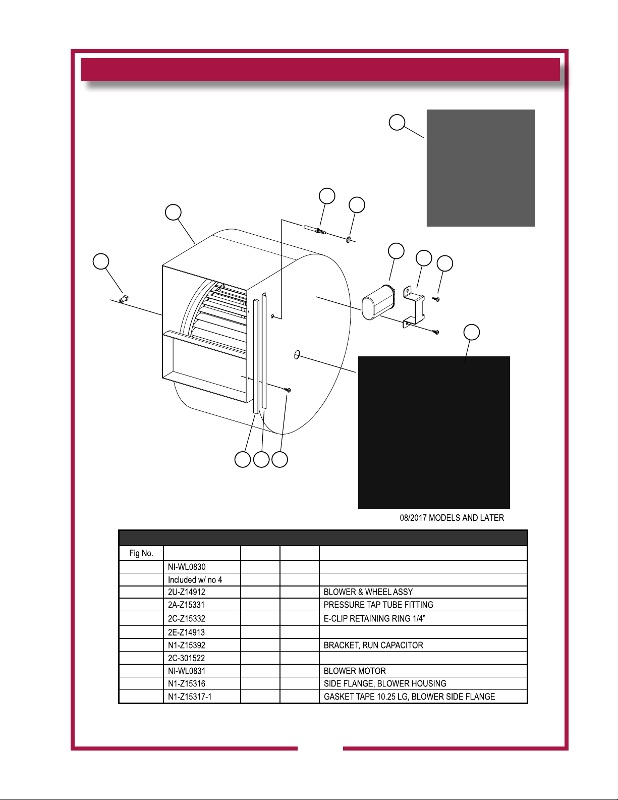
EXPLODED VIEW & PARTS LIST
Universal Hood Internal Control (Detail A)
1
4
3
2
5
6
7
8
9
11 10 8
Blower & Motor Assy
Part No WVU48
11 LOWER ASSEMBLY
21
31
41
51
61
71
84
91
M522 p/n 2M-Z23068 OpM WVU- Universal Hood
10 12
11 12
Detail A
*
DETAIL A, Blower & Motor Assy
Description
RUN CAPACITOR, 10MFD, 370V
SCREW 8X12 RPH PAN SELF DRILLING
ASSEMBLY
47
Page 50
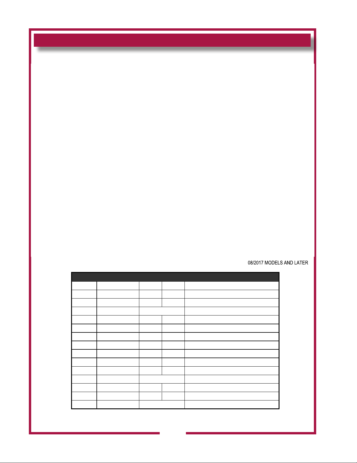
EXPLODED VIEW & PARTS LIST
Universal Hood Internal Control (Detail b)
DETAIL B, Internal Control Panel Assy
Fig NoP art Number WVU48
1N 1-Z15362 12
22 E-Z14673
32 P-Z17415 1
4
N1-Z14886 12
5N 1-Z15531
62 E-Z15352 12
2E-Z15365 12
7
82 E-302591 12
9
N1-Z22130 12
10
11 2C-08-07-0042 2
12 2C-Z7165
13
14
2K-Y5093 24 BUSHING-SNAP #SB-1000-12
2C-Z18059
2J-44834 1 BUZZER
12 PRESSURE SWITCH
12
15
12
*
escription
BRACKET, PRESSURE SWITCH
TIMER,CUBE/ RELAY
BRACKET,PRESSURE SWITCH
BRACKET,HEPA PRESS.SWITCH
VACUUM SWITCH,HEPA FILTER
PRESSURE SWITCH
SWITCH VACUUM #2
MOUNTING TRAY, INTERNAL CONTROLS
SCREW 8-32X5/8 RHP STL NP
NUT 8-32 HEX SS W/EXT WSH
CABLE CLAMP, 0.5 INCH NYLON
M522 p/n 2M-Z23068 OpM WVU- Universal Hood
48
Page 51
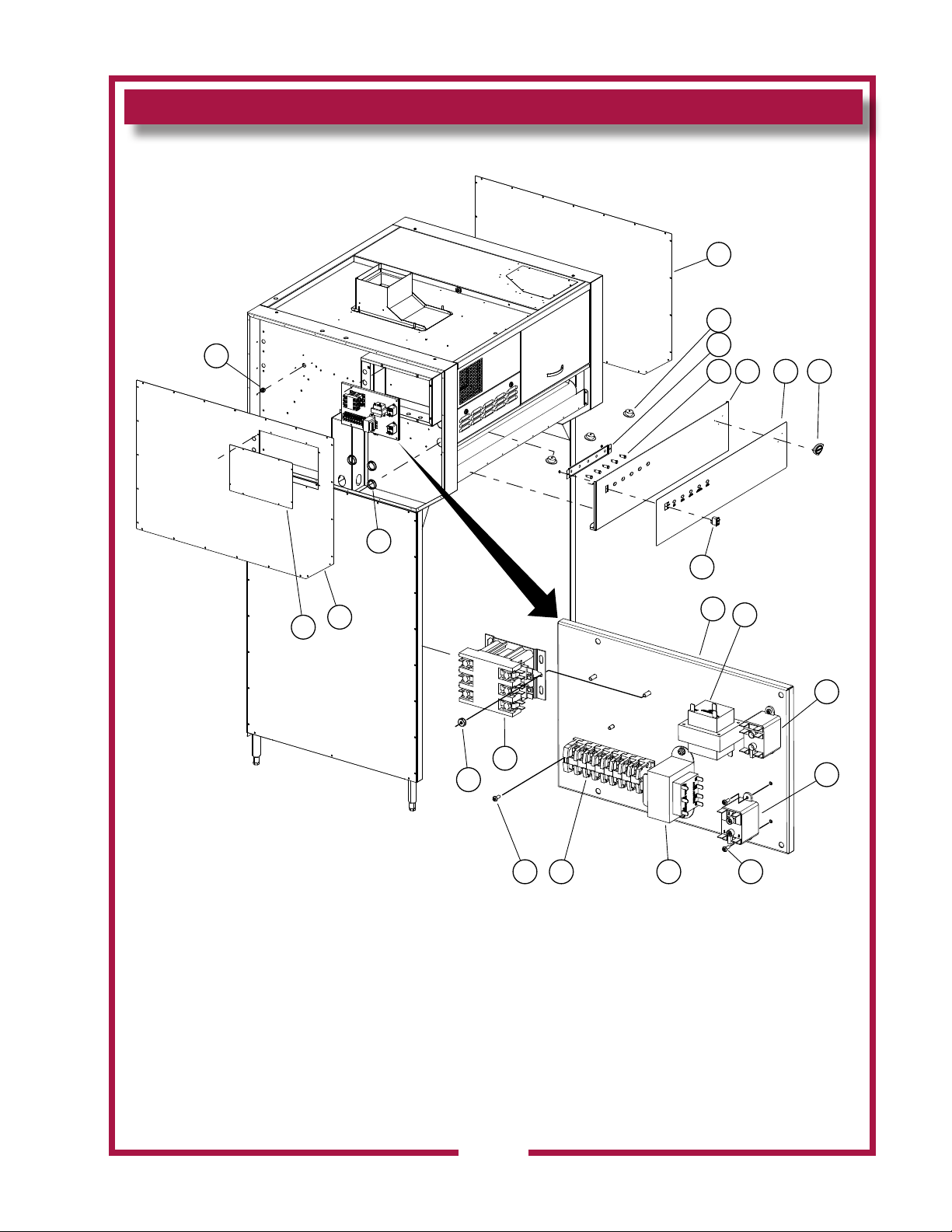
EXPLODED VIEW
Universal Hood Electrical Components
1
2
21
20
19
18
17
16
8
435
9
6 7
10
11
12
SK2557 Rev. - 1/16/2012
Electrical Components
M522 p/n 2M-Z23068 OpM WVU- Universal Hood
13141513
49
Page 52
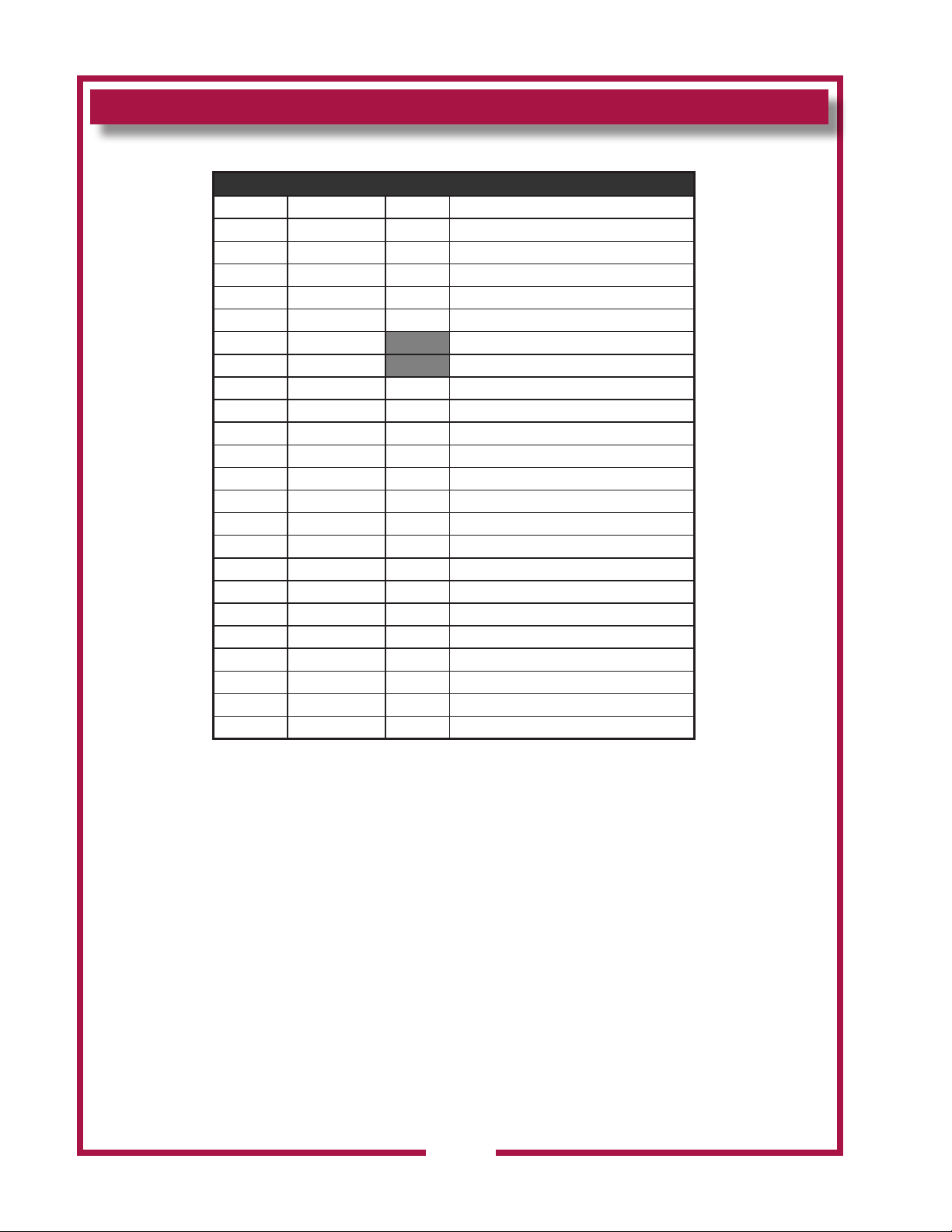
PARTS LIST
Universal Hood Electrical Components
Fig No. Part No WVU48 Description
1 N1-Z14142 1 COVER, HOOD SIDE RIGHT
2 N1-WL0245 3 LED FLOODLIGHT, 45W CW w/TERM
3 N1-Z15418 1 MOUNTING PLATE, CTRL LIGHT
4 N1-WL0281 5 LIGHT SIGNAL, CLEAR LED w/TERM
5 N1-WL0250 1 CONTROL PANEL, FRONT ASSY
5 N1-WL0278 CONTROL PANEL, FRONT ASSY
6 2M-Z14069 GRAPHIC PANEL, NO SWITCH
6 2M-Z14510 1 GRAPHIC PANEL W/ SWITCH
7 2M-306719 1 LOGO WELLS DIECAST SHIELD
8 2E-305295 1 SWITCH ROCKER 250V 10A GR
9 N1-Z15435 1 ELEC. AUTOMAN BKT. MODIFY
10 2E-Z15018 1 TRANSFORMER, 208/240 12V
11 2E-44514 1 RELAY 208-240V COIL
12 2E-Z15353 1 RELAY, 120V COIL, SPNO
13 2C-1488 6 SCREW 6-32X3/8 RHP STL NP
14 2E-Z15335 1 TRANSFORMER, 208/240
15 WS-WL0282 1 TERMINAL BLOCK ASSY
16 2E-Z14960 1 CONTACTOR, 40A
17 2C-40680 2 NUT 10-32 HEX KEPS MS SS
18 2K-Y8571 3 BUSHING SNAP 2 1/8
19 N1-Z14141 1 COVER, HOOD SIDE LEFT
20 N1-Z15344 1 COVER,SIDE ELECTRIC BOX
21 2K-8043 2 BUSHING HEYCO SB-875-10
Control Panel
50
M522 p/n 2M-Z23068 OpM WVU- Universal Hood
Page 53
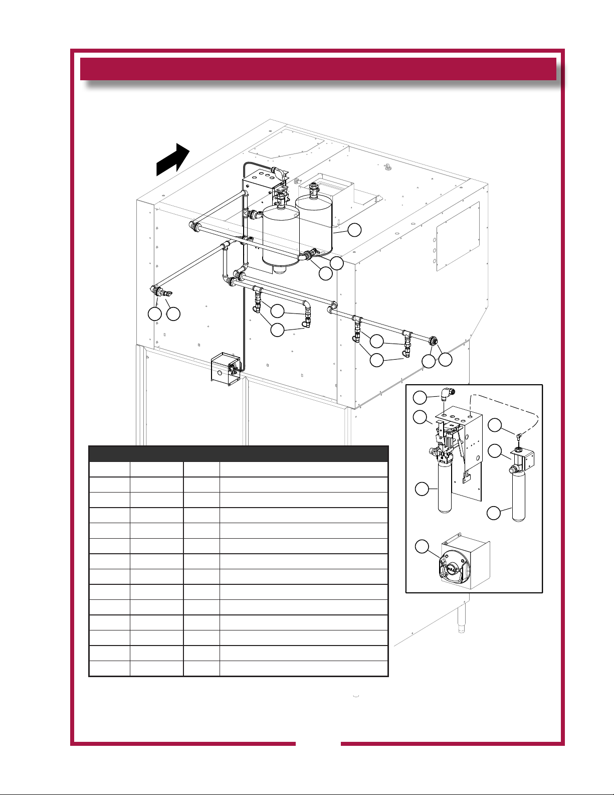
EXPLODED VIEW & PARTS LIST
Universal Hood Suppression System
Front
7
6
1
21
3
4
Suppression System
Fig. No Part No WVU48 Description
1 2K-47269 8 ADAPTER 3/8IN QUICK CON A
2 2O-47267 1 NOZZLE ANSUL 1N
3 2O-307481 5 ADAPTER SWIVEL ANSUL
4 2O-Z14574 4 NOZZLE, #245
5 2C-Z15115 1 HEX HEAD PIPE PLUG 3/8NPT
6 2O-302931 1 NOZZLE 1 W
7 2O-304433 2 TANK SS ANSULEX 1.5 GALLO
8 2O-47272 1 PULLEY ELBOW
9 N1-Z15435 1 ELEC. AUTOMAN BKT MODIFY
10 2O-Z14918 1 ANSUL CARTRIDGE LT-30-R
11 2O-308131 1 REMOTE PULL STATION RED
12 2O-307966 - ANSUL REG. ACTUATOR ASSY
13 2K-Z15635 - ELBOW, MALE 7/16-20X1/4NPT
3
4
5
1
Suppression System
8
9
10
11
13
12
10
M522 p/n 2M-Z23068 OpM WVU- Universal Hood
SK2558 Rev. A 1/16/2015
51
Page 54
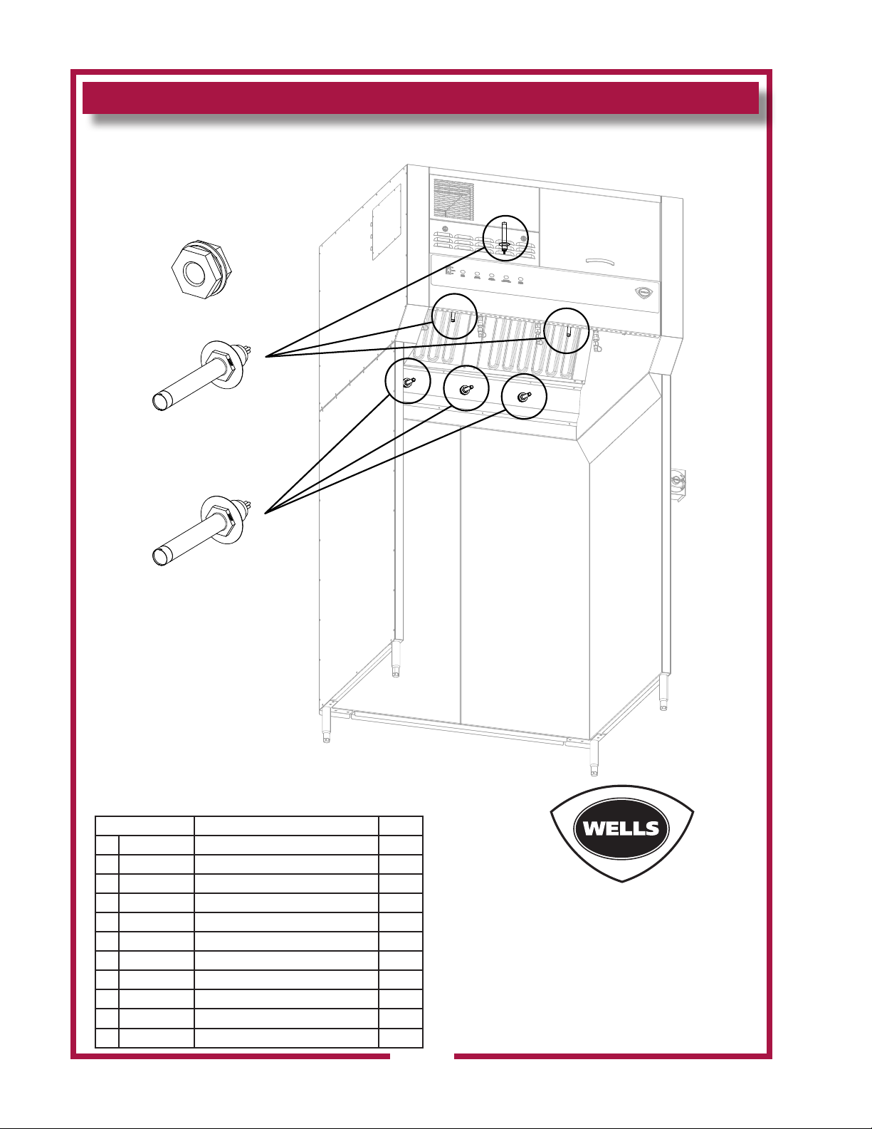
SK2559 Rev. A 7/25/2012
EXPLODED VIEW & PARTS LIST
Universal Hood Detection System
Adapter 1/2” Quick Seal
Part No: 2T-Z15320
Thermal Detector-225°F
Part No: 2T-Z15320
Thermal Detector-275°F
Part No: 2T-Z16137
Ansul Deployments are not covered under warranty. Technical
service (800)-264-7827 needs to be contacted immediately and
a deployment kit of parts needs to be replaced before unit is
put back in service.
WS-WL0964 DEPLYMNT KIT, WVU-48 QTY
Detection System
1 2J-44834 BUZZER 220V ROHS 1
2 2E-Z15352 VACUUM SWITCH,HEPA FILTER 1
3 2E-305295 SWITCH ROCKER 250V 10A 1
4 N1-Z22134 BLOWER MOTOR, MODIFIED 1
5 2U-200577 MOTOR, FAN 240V, HI-OUT PUT 2
6 WS-Z17920 PKG,TIMER & BRACKET ASM 1
7 2E-Z15365 PRESSURE SWITCH 1
8 2E-200387 CORD FAN PLUG 2
9 N1-WL0171 FILTER HEPA/CARBON PACK 1
10 2I-302579 FILTER PRE HOOD UNIVERSAL 2
11 2I-Z22132 MOUNT, SILICONE, 4
M522 p/n 2M-Z23068 OpM WVU- Universal Hood
52
Page 55

EXPLODED VIEW & PARTS LIST
Universal Hood Base Assy
3
2
1
13
17
4
15
16
5
5
6
7
8
9
10
11
12
2
Model: WVU48 Base Assy
Base Assembly
Fig No. Part No WVU48 Description
1 N1-Z15193 2 BASE DEFLECTOR
2 2C-35487 66 SCREW 8-32X5/16 PH TR HD
3 2C-1825 16 WASHER #8 EXT STL NP
4 N1-WL0176 1 BASE,SUPPORT ASSY LFT
N1-Z14147 2 BASE,BACK SUPPORT
5
N1-Z14149 BASE,BACK SUPPORT 8FT
6 2C-6517 70 NUT 1/4-20 HEX STL NP
7 2C-A27469 70 WASHER,FLAT 1/4IN 7/8OD 1
8 2C-Z5555 70 BOLT 1/4-20 X .75 HEX SS
9 2C-31053 4 NUT 8-32 KEPS MS NICKEL
10 2P-70903-05 1 PLG BTN PLTD MTL 7/8
11 N1-WL0126 1 BOX, MANUAL PULL ASSEMBLY
N1-WL0180 1 COVER,BASE SIDE RT ASSY
12
N1-Z14152 1 COVER, BASE SIDE LEFT
2A-307628
13
M522 p/n 2M-Z23068 OpM WVU- Universal Hood
2A-Z16259 LEG, 10” ADJ. 1/2-13 SS (Optional)
14 N1-WL0177 1 BASE,SUPPORT ASSY RT
4
15 2O-308131 1 REMOTE PULL STATION RED
16 2C-31730 2 SCREW 8-32X1/2 PH TR HD M
14
LEG 6 ADJ 1/2-13 SS
53
SK2561 Rev. A 11/18/2013
Page 56

PARTS & SERVICE
DESCRIPTION PART NO.
IMPORTANT: Use only
factory authorized service parts
andreplacementlters.
For factory authorized service,
or to order factory authorized
replacement parts, contact
your Wells authorized service
agency, or call:
Wells Manufacturing
265 Hobson St.
Smithville, TN 37166 USA
Service Dept.
phone: (800) 264-7827
fax: (314) 781-2714
Service Parts Department
can supply you with the name
and telephone number of the
WELLS authorized service
agency nearest you.
CUSTOMER SERVICE DATA
please have this information available if calling for service
RESTAURANT _____________________________ LOCATION _____________
INSTALLATION DATE ________________________ TECHNICIAN ___________
SERVICE COMPANY ________________________________________________
ADDRESS ___________________________ STATE ______ ZIP__________
TELEPHONE NUMBER (_____)_____-_________
EQUIPMENT MODEL NO. _____________EQUIPMENT SERIAL NO. _______________
VOLTAGE: (check one) 208 240
54
M522 p/n 2M-Z23068 OpM WVU- Universal Hood
Page 57
265 Hobson Street Smithville, TN 37166
Application for Ventless Approvals
Please print or type. The application
Customer Information
Business Name
Address
City
State
Zip
Phone Number
Mobile Number
Email Address
Project Contact Information
Name
Email Address
Phone Number
Company
Dealer Information
Name
Email Address
Phone Number
Company
Wells Ventless
Model Number
How many pieces of equipment under hood
Project contact
initial
[
(800) 264-7827 [email protected]
All Wells ventless models’ dimensions, electrical requirements,
and venting requirements are in the specification sheet and
manuals. All documentation can be found at wells-mfg.com.com.
Any questions please call Wells at (800) 264-7827
Please supply documentation with application:
• Spec Sheets (equipment under the hoods) for non-Middleby brands
• Manuals (equipment under the hood)) for non-Middleby brands
NYC and Chicago
• Please contact a Wells representative to inquire about additional documentation
must be fully completed to be
Approved. Please complete each
section if applicable. Submit this
application and all supporting
documents with your PO.
1.
2.
3.
2M-303912 REV E (07-2019)
Page 58
265 Hobson Street Smithville, TN 37166
Equipment List
(Please Attach All Spec Sheets)
Wells Hood
Model # list)
Initial
Signature Disclaimer
Name (Please Print)
Signature
Date
Wells Approval Signature (Wells Authorized Representative)
Name (Please Print)
Signature
Date
(800) 264-7827 [email protected]
Manufacturer and Model Number
(1-3 from Wells
Project Contact
➢ I understand that the Wells Ventless system is designed based on the information supplied above, changes
made can affect its performance and may affect the Ventless system warranty.
➢ I understand that incomplete or missing information on the equipment to be used under the Ventless system will
affect the equipment approval process and will delay this order. No production date will be scheduled until
complete information is received.
➢ I understand that any equipment changes made after this process may affect the Wells Ventless equipment
including its performance or overall warranty of the of the Ventless system
➢ I understand that a Wells Representative must perform a start-up/training course before warranty will begin.
2M-303912 REV E (07-2019)
Page 59

Page 60

 Loading...