

Page 1
WELLS BLOOMFIELD, LLC
10 Sunnen Dr., St. Louis, MO 63143
telephone: 314-678-6314
fax: 314-781-2714
www.wellsbloomfield.com
304
OWNERS MANUAL
BUILT-IN
ELECTRIC
AUTOLIFT
FRYERS
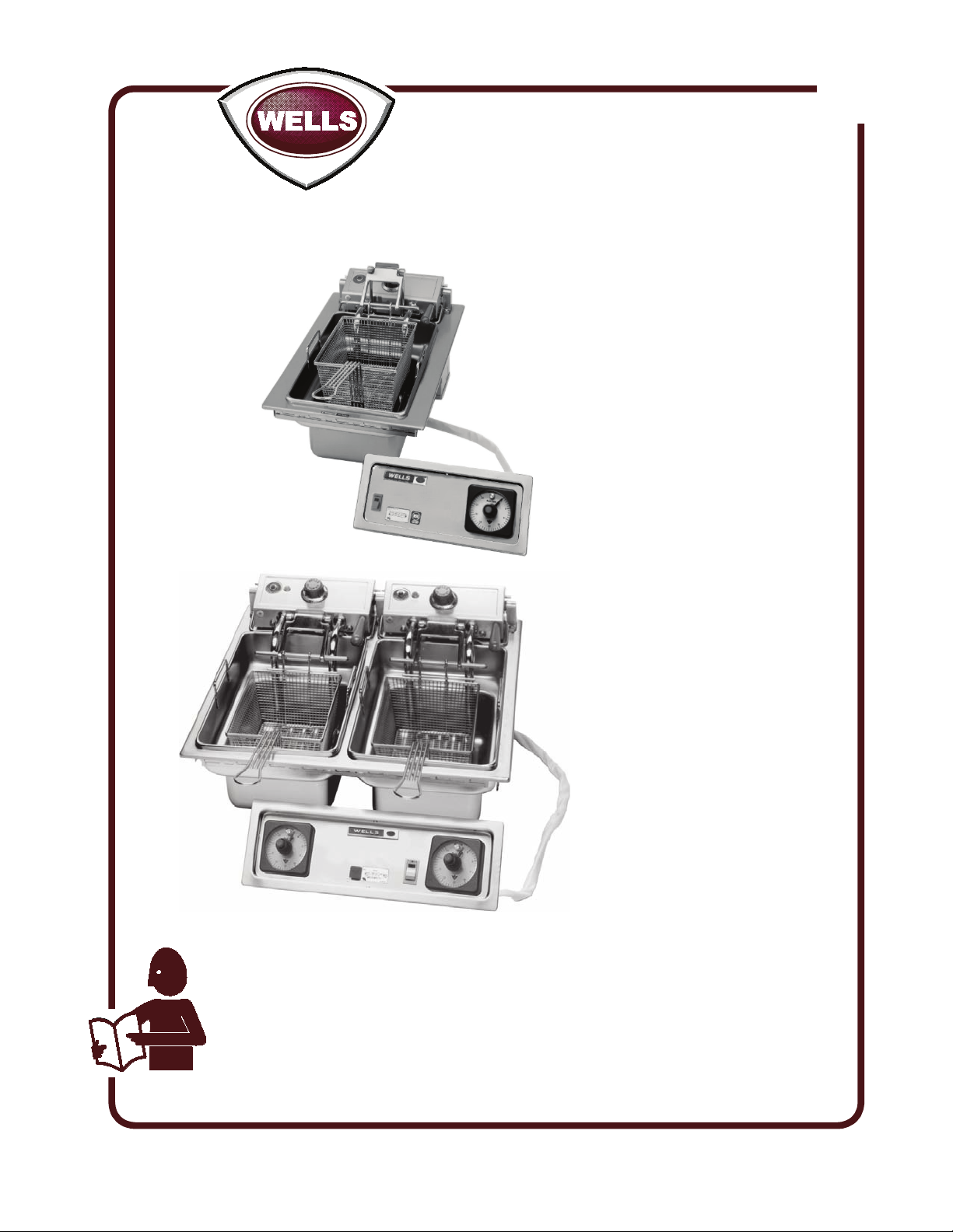
Model F886
Model F586
MODELS
F586
F686
F886
Includes
INSTALLATION
USE & CARE
EXPLODED VIEW
PARTS LIST
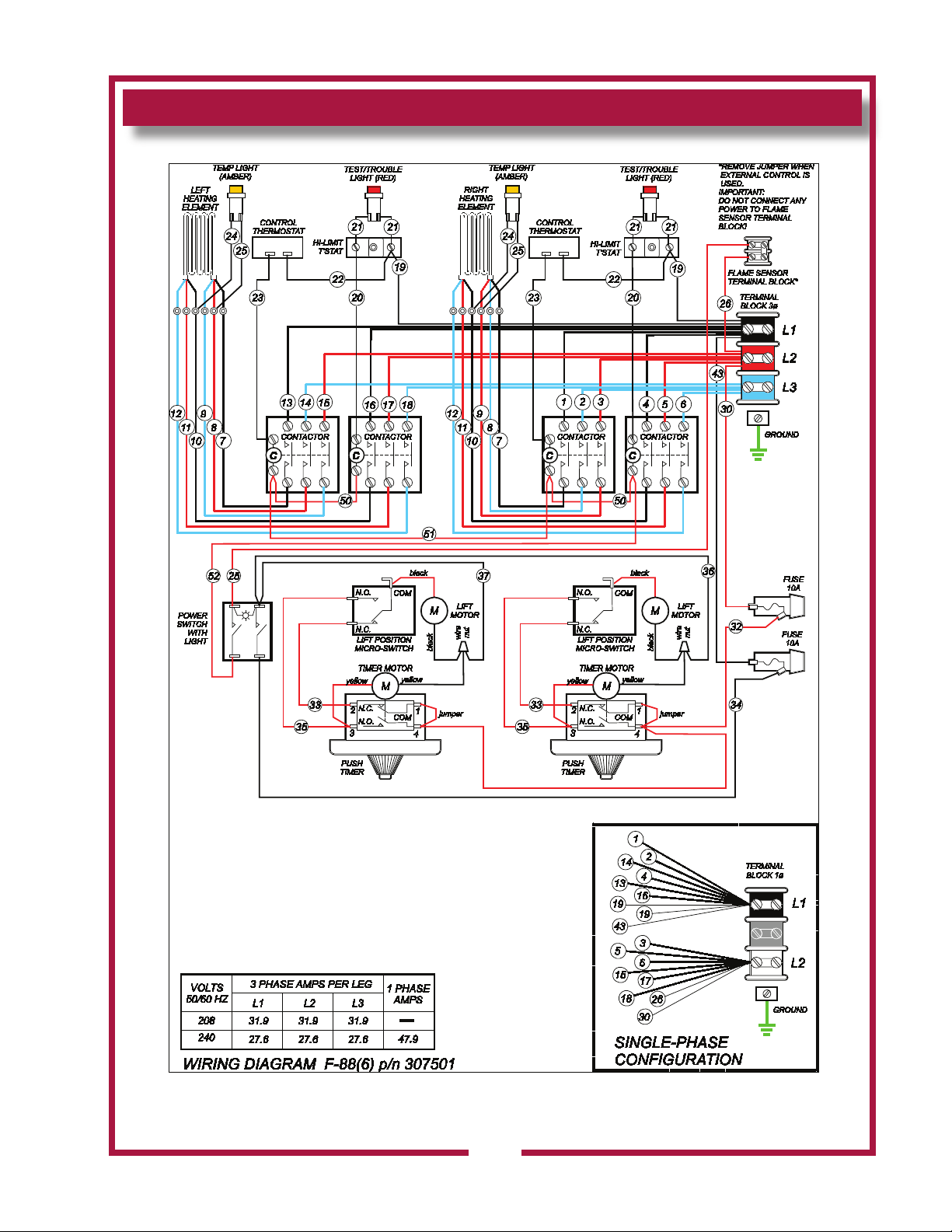
WIRING DIAGRAM
IMPORTANT: DO NOT DISCARD THIS MANUAL
This manual is considered to be part of the appliance and is to be given to the OWNER or
MANAGER of the restaurant, or to the person responsible for TRAINING OPERATORS of
this appliance. Additional manuals are available from your WELLS DEALER.
THIS MANUAL MUST BE READ AND UNDERSTOOD BY ALL PERSONS USING OR
INSTALLING THIS APPLIANCE. Contact your WELLS DEALER if you have any
questions concerning installation, operation or maintenance of this equipment.
p/n 2M-307591 Rev. C M313 110113
Page 2

LIMITED WARRANTY STATEMENT
Unless otherwise specied, all commercial cooking
equipment manufactured by WELLS BLOOMFIELD, LLC is
warranted against defects in materials and workmanship
for a period of one year from the date of original installation
or 18 months from the date of shipment from our factory,
whichever comes rst, and is for the benet of the original
purchaser only.
THIS WARRANTY IS THE COMPLETE AND ONLY
WARRANTY, EXPRESSED OR IMPLIED IN LAW
OR IN FACT, INCLUDING BUT NOT LIMITED TO,
WARRANTIES OF MERCHANTABILITY OR FITNESS
FOR ANY PARTICULAR PURPOSE, AND/OR FOR
DIRECT,INDIRECT OR CONSEQUENTIAL DAMAGES IN
CONNECTION WITH WELLS BLOOMFIELD PRODUCTS.
This warranty is void if it is determined that, upon inspection
by an authorized service agency, the equipment has been
modied, misused, misapplied, improperly installed, or
damaged in transit or by re, ood or act of God. It also
does not apply if the serial nameplate has been removed,
or if service is performed by unauthorized personnel.
The prices charged by Wells Bloomeld for its products
are based upon the limitations in this warranty. Seller’s
obligation under this warranty is limited to the repair of
defects without charge by a Wells Bloomeld factory
authorized service agency or one of its sub-service
agencies. This service will be provided on customer’s
premises for non-portable models. Portable models (a
device with a cord and plug) must be taken or shipped
to the closest authorized service agency, transportation
charges prepaid, for service. In addition to restrictions
contained in this warranty, specic limitations are shown in
the Service Policy and Procedure Guide. Wells Bloomeld
authorized service agencies are located in principal cities.
This warranty is valid in the United States and Canada and
void elsewhere. Please consult your classied telephone
directory, your foodservice equipment dealer or contact:
Wells Bloomeld, LLC
10 Sunnen Dr., St. Louis MO 63143 USA
phone (314) 678-6314 or fax (314) 781-2714
for information and other details concerning warranty.
SERVICE POLICY AND PROCEDURE GUIDE and ADDITIONAL WARRANTY EXCLUSIONS
1. Resetting of safety thermostats, circuit breakers, over
load protectors, and/or fuse replacements are not
covered by this warranty unless warranted conditions
are the cause.
2. All problems due to operation at voltages or phase
other than specied on equipment nameplates are
not covered by this warranty.
Conversion to correct voltage and/or phase must be
the customer’s responsibility.
3. All problems due to electrical connections not made
in accordance with electrical code requirements
and wiring diagrams supplied with the equipment are
not covered by this warranty.
4. Replacement of items subject to normal wear, to
include such items as knobs, light bulbs; and, normal
maintenance functions including adjustments of
thermostats, adjustment of micro switches and
replacement of fuses and indicating lights are not
covered by warranty.
5. Damage to electrical cords and/or plug due to exposure
to excessive heat are not covered by this warranty.
6. Full use, care, and maintenance instructions supplied
with each machine. Noted maintenance and
preventative maintenance items, such as servicing and
cleaning schedules, are customer responsibility. Those
miscellaneous adjustments noted are customer
responsibility. Proper attention to preventative
maintenance and scheduled maintenance procedures
will prolong the life of the appliance.
7. Travel mileage is limited to sixty (60) miles from an
Authorized Service Agency or one of its sub-service
agencies.
8. All labor shall be performed during regular working
hours. Overtime premium will be charged to the buyer.
9. All genuine Wells replacement parts are warranted
for ninety (90) days from date of purchase on non-
warranty equipment. This parts warranty is limited only
to replacement of the defective part(s). Any use of
non-genuine Wells parts completely voids any
warranty.
10. Installation, labor, and job check-outs are not
considered warranty and are thus not covered by this
warranty.
11. Charges incurred by delays, waiting time or operating
restrictions that hinder the service technician’s ability to
perform service are not covered by warranty. This
includes institutional and correctional facilities.
SHIPPING DAMAGE CLAIM PROCEDURE
NOTE: For your protection, please note that equipment
in this shipment was carefully inspected and packaged
by skilled personnel before leaving the factory. Upon
acceptance of this shipment, the transportation company
assumes full responsibility for its safe delivery.
IF SHIPMENT ARRIVES DAMAGED:
VISIBLE LOSS OR DAMAGE: Be certain that any
1.
visible loss or damage is noted on the freight bill or
express receipt, and that the note of loss or damage is
signed by the delivery person.
2. FILE CLAIM FOR DAMAGE IMMEDIATELY:
Regardless of the extent of the damage.
3. CONCEALED LOSS OR DAMAGE: if damage is
unnoticed until the merchandise is unpacked, notify the
transportation company or carrier immediately, and le
“CONCEALED DAMAGE” claim with them. This
should be done within fteen (15) days from the date
the delivery was made to you. Be sure to retain the
container for inspection.
Wells Bloomeld cannot assume liability for damage or loss
incurred in transit. We will, however, at your request, supply
you with the necessary documents to support your claim.
xi
304 p/n 2M-307591 Owners Manual Built-In Electric Autolift Fryers
Page 3
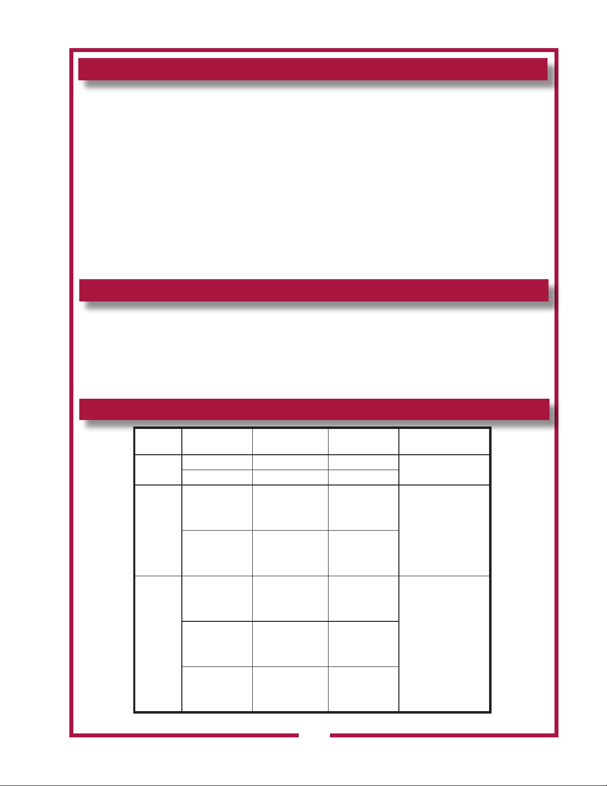
TABLE OF CONTENTS
WARRANTY xi
SPECIFICATIONS 1
FEATURES & OPERATING CONTROLS 2
PRECAUTIONS & GENERAL INFORMATION 3
AGENCY LISTING INFORMATION 4
INSTALLATION 4
OPERATION 6
CLEANING INSTRUCTIONS 7
TROUBLESHOOTING SUGGESTIONS 9
MAINTENANCE 10
EXPLODED VIEW & PARTS LIST 11
WIRING DIAGRAM 18
PARTS & SERVICE 21
CUSTOMER SERVICE DATA 21
INTRODUCTION
Thank You for purchasing this Wells Bloomeld appliance.
Proper installation, professional operation and consistent maintenance of this appliance will ensure that
it gives you the very best performance and a long, economical service life.
This manual contains the information needed to properly install this appliance, and to use and care for
the appliance in a manner which will ensure its optimum performance.
SPECIFICATIONS
304 p/n 2M-307591 Owners Manual Built-In Electric Autolift Fryers
MODEL VOLTS AMPS WATTS
F586
F686
F886
208 VAC 1 ø 27.6A 5.75KW
240 VAC 1ø 24.0A 5.75KW
L1=38.3A
208 VAC 3ø
208/240V 3ø
208 VAC 3ø
240 VAC 3ø
480 VAC 3ø
L2=22.1A
L3=22.1A
L1=28.8/33.2A
L3=16.6/19.2A
L1=31.9A
L2=31.9A
L3=31.9A
L1=27.6A
L3=27.6A
L1=13.8A
L3=13.8A
9.2KW
6.9/9.2KWL2=16.6/19.2A
11.5KW
11.5KWL2=27.6A
11.5KWL2=13.8A
POWER SUPPLY
CORD
NOT SUPPLIED
NOT SUPPLIED
NOT SUPPLIED
1
Page 4
FEATURES & OPERATING CONTROLS
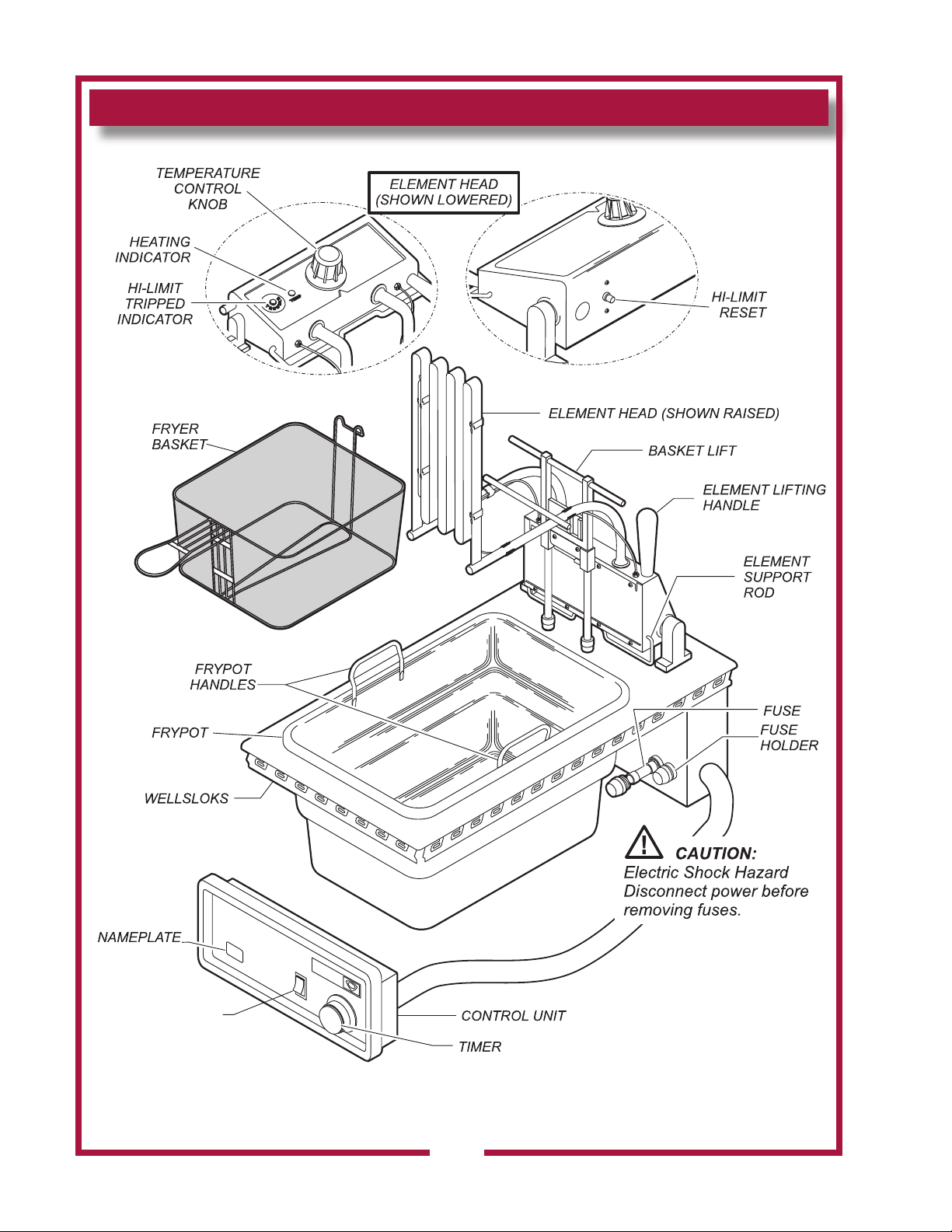
POWER SWITCH
IL2055
Fig. 1 Built-In Fryer Features & Operating Controls
F586 Shown - F686 and F-886 Similar
304 p/n 2M-307591 Owners Manual Built-In Electric Autolift Fryers
2
Page 5
PRECAUTIONS AND GENERAL INFORMATION
DANGER:
Contact with hot oil will cause severe burns. Always wear protective clothing and heat
resistant gloves when operating the fryer or ltering the oil.
SEVERE BURN HAZARD
WARNING: ELECTRIC SHOCk HAZARD
All servicing requiring access to non-insulated components must be performed by
qualied service personnel. DO NOT open any access panel that requires the use of
tools. Failure to heed this warning may result in severe electric shock.
WARNING: BURN HAZARD
DO NOT allow water or ice to contact hot oil. DO NOT attempt to cool the oil with
water or ice. The water will boil violently, causing hot oil to foam and splatter.
Contact with splattering or foaming hot oil will cause severe burns.
This appliance is intended for use in commercial establishments only.
This appliance is intended to prepare food for human consumption.
No other use is recommended or authorized by the manufacturer or its
agents.
Operators of this appliance must be familiar with the appliance use,
limitations and associated restrictions. Operating instructions must be
read and understood by all persons using or installing this appliance.
Cleanliness of this appliance is essential to good sanitation. Read and
follow all included cleaning instructions and schedules to ensure the
safety of the food product.
Disconnect this appliance from electrical power before performing any
maintenance or servicing.
DO NOT submerge this appliance in water. This appliance is not jet
stream approved. Do not direct water jet or steam jet at this appliance,
or at any control panel or wiring. Do not splash or pour water on, in or
over any controls, control panel or wiring.
Exposed surfaces of this appliance can be hot to the touch and may
cause burns.
The technical content of this manual, including any wiring diagrams,
schematics, parts breakdown illustrations and/or adjustment
procedures, is intended for use by qualied technical personnel.
Any procedure which requires the use of tools must be performed by a
qualied technician.
This manual is considered to be a permanent part of the appliance.
This manual and all supplied instructions, diagrams, schematics,
parts breakdown illustrations, notices and labels must remain with the
appliance if it is sold or moved to another location.
This appliance is made in the USA. Unless otherwise noted, this
appliance has American sizes on all hardware.
304 p/n 2M-307591 Owners Manual Built-In Electric Autolift Fryers
CAUTION:
BURN HAZARD
Contact with hot oil may
cause burns.
fryer beyond
DO NOT
MAX OIL
ll
line
on frypot.
For disposal of oil use only
a container specically
designed for the disposal
of hot oil. DO NOT ll
hot oil disposal container
beyond MAX OIL line.
CAUTION:
RISk OF
DAMAGE
DO NOT connect or
energize this appliance
until all installation
instructions are read and
followed. Damage to the
appliance will result if
these instructions are not
followed.
CAUTION:
HOT SURFACE
Exposed surfaces can be hot
to the touch and may cause
burns.
3
Page 6
AGENCY LISTING INFORMATION
This appliance conforms to NSF Standard 4 for sanitation only if
installed in accordance with the supplied Installation Instructions.
This appliance is Underwriters Laboratory recognized ( ). Since this
appliance is only a single component of a complete installation, the
nished installation of this unit requires additional evaluations to
Underwriters Laboratory standards.
Refer to Installation Instructions included with the appliance for
Underwriters Laboratories conditions of acceptability, electrical
requirements and other installation concerns.
INSTALLATION
STD 4
UNPACkING & INSPECTION
Carefully remove the appliance from the carton. Remove all protective
plastic lm, packing materials and accessories from the appliance
before connecting electrical power or otherwise performing any
installation procedure.
Carefully read all instructions in this manual and the Installation
Instruction Sheet packed with the appliance before starting any
installation.
Read and understand all attached labels and diagrams.
Carefully account for all components and accessories before discarding
packing materials. Store all accessories in a convenient place for later
use.
CUT-OUT AND INSTALLATION
Cutouts
Fryers may be installed in METAL COUNTERS ONLY.
a.
Cutout dimensions for fryers and control panels are listed on
b.
the Installation Instructions provided with the fryer.
Refer to the Installation Instructions for Underwriters
c.
Laboratories Conditions of Acceptability.
Mounting the fryer:
Verify that provided sealants are applied to the under side of
a.
the fryer top ange prior to setting the unit into the cutout.
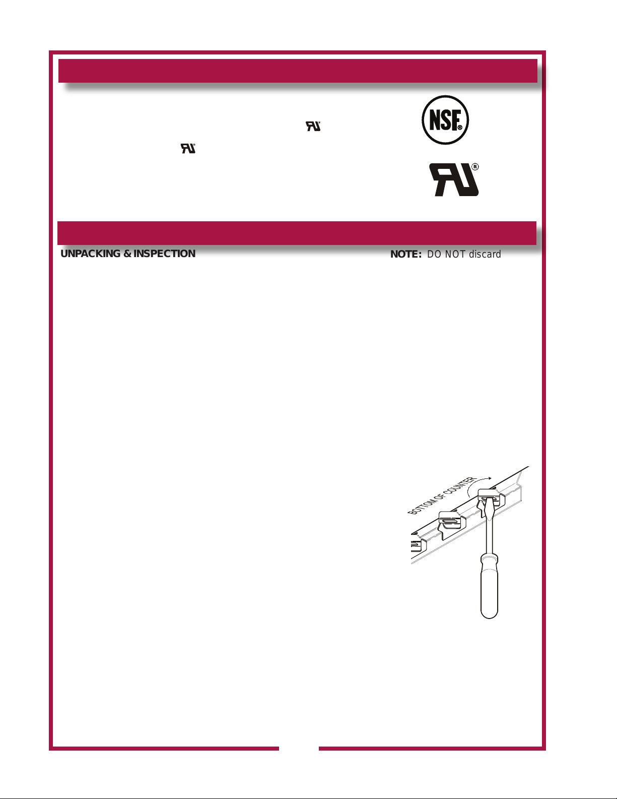
After installation, verify that the tabs on the Wellsloks are
b.
turned out to lock the appliance into the counter (see Fig. 2).
Apply a thin bead of food-grade silicone sealant around the
c.
ange to seal it to the counter.
Refer to the Installation Instructions for required clearances. Maintain
required clearances between the appliance and adjacent combustible
and non-combustible surfaces.
Sufcient overhead clearance must be provided to allow the element
assembly to be raised. Refer to the Installation Instruction Sheet for
required clearances.
Avoid storing ammable or combustible materials near the appliance.
This includes gasoline and other fuels, mops, rags and wrapping paper.
NOTE: DO NOT discard
the carton or other packing
materials until you have
inspected the appliance for
hidden damage and tested it
for proper operation.
Refer to SHIPPING DAMAGE
CLAIM PROCEDURE on the
inside front cover of this
manual.
IMPORTANT: This is a GEN-
ERAL GUIDE. For specic
equipment and cutout dimensions, and other installation
details, refer to the Installation
Instructions supplied with the
Fig. 2 Set the Wellslloks
appliance.
IMPORTANT: Water damage caused by failure to
set Wellsloks, failure to
install gasket, or failure to
seal ange to counter is NOT
covered by warranty.
304 p/n 2M-307591 Owners Manual Built-In Electric Autolift Fryers
4
Page 7
INSTALLATION (continued)
WARNING:
ELECTRIC SHOCk HAZARD
All servicing requiring access to non-insulated electrical components must be
performed by a factory authorized technician.
DO NOT open any access panel which requires the use of tools. Failure to follow this
warning can result in severe electrical shock.
FRYER ELECTRICAL INSTALLATION
Fryers must be connected directly to an appropriately sized electric
circuit. Conduit and strain relief must be provided by the electrician.
Refer to equipment nameplate for voltage and amperage requirements.
Raise the element head, remove the frypot and the cover at the rear
of the fryer to gain access to the terminal block. The electrical inlet is
provided by a knock-out in the rear panel.
If an equipment shutdown interface is required by local re code,
the ame sensor terminal block may be accessed by removing the
back panel. Replace the jumper of the terminal block with wiring to a
normally closed contact of the building re management system.
DO NOT connect power to the ame sensor terminal block. Wiring and
contacts must be capable of handling 30 amps.
F-686 and F-886 fryers are shipped from the factory wired for three
phase. Conversion to single phase must be performed in the eld by
the electrician.
CAUTION:
RISk OF
DAMAGE
DO NOT connect or energize
this appliance until all
installation instructions are
read and followed. Damage
to the appliance will result
if these instructions are not
followed.
CAUTION:
SHOCk HAZARD
The ground lug of F586
and F-686 fryers must be
connected to a suitable
building electric ground.
304 p/n 2M-307591 Owners Manual Built-In Electric Autolift Fryers
IMPORTANT:
Damage due to being
connected to the wrong
voltage or phase is NOT
covered by warranty.
NOTE:
F-58 and F-68 fryers are
shipped from the factory
with the basket lift in the UP
position.
5
Page 8
OPERATION
DANGER: BURN HAZARD
Contact with hot oil will cause severe burns.
Always wear protective clothing and heat resistant gloves when operating the fryer.
CAUTION:
HOT SURFACE
Exposed surfaces can be hot
to the touch and may cause
burns.
Fig.
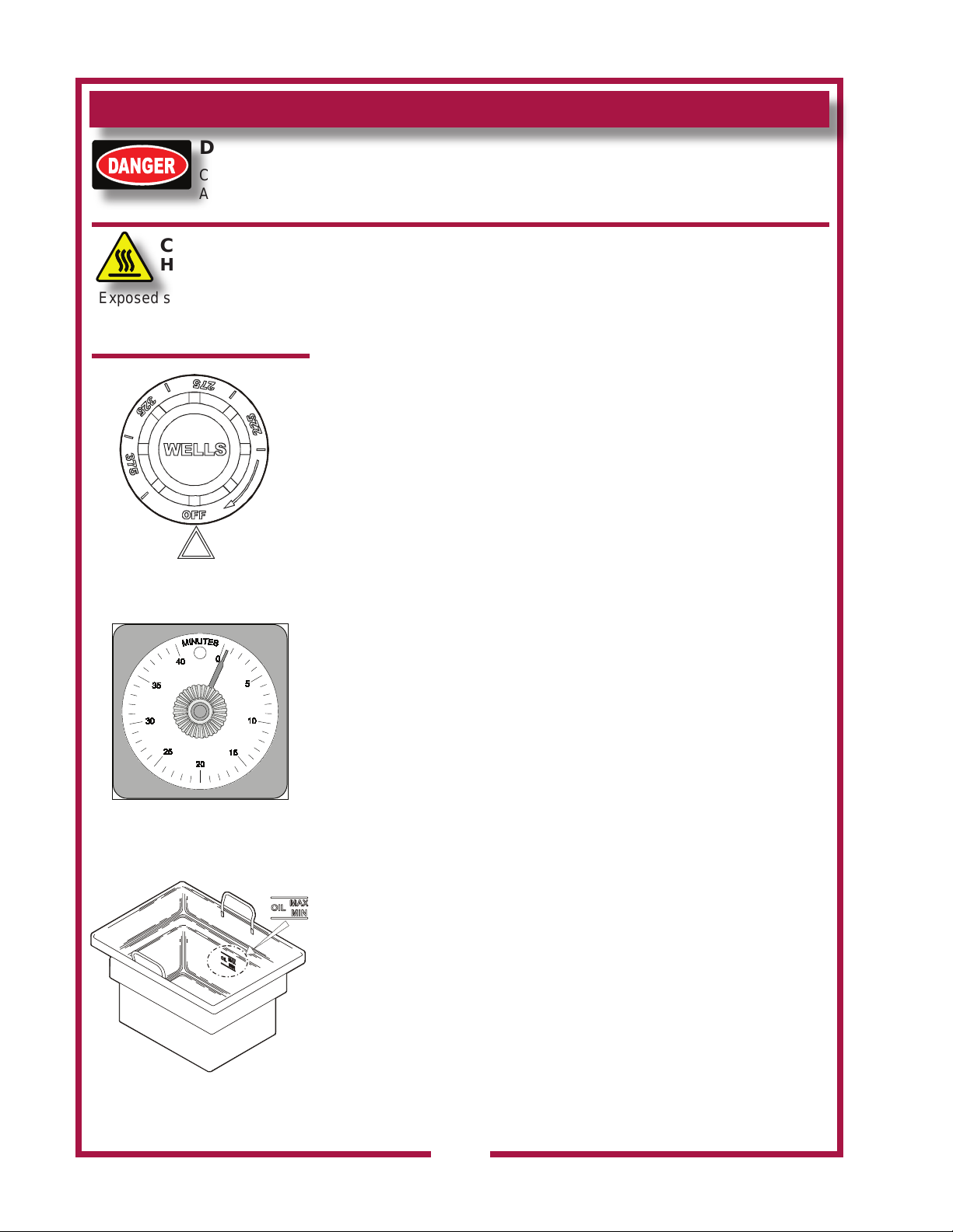
3 Temperature Control
Knob
Fig. 4 Timer
NORMAL OPERATION
1. a. Be sure TEMPERATURE CONTROL KNOB is turned to OFF.
b. Lower element head into frypot by pulling back on
ELEMENT LIFTING HANDLE, raising ELEMENT HEAD
SUPPORT ROD, then carefully lowering elements into frypot.
2.
Fill FRYPOT with commercial-grade liquid shortening to MIN OIL
line. Capacity is 15 pounds (F-58), or 30 pounds (F-68 and F-88).
IMPORTANT: DO NOT
Adding too much oil will allow frypot to overow during operation. For
best results, always use top grade commercial shortening made
specially for frying. Maintain proper oil level in frypot during operation.
3. Turn TEMPERATURE CONTROL KNOB to desired temperature.
Press HEATER switch to ON position. HEAT INDICATOR will glow.
When oil reaches the desired temperature, heat indicator will go
out. Heat indicator will go off and on during operation as thermostat
cycles to maintain temperature.
For best results: DO NOT
setting higher than is required for the food product.
4.
Load either or both baskets no more than 1/2 full with food product.
DO NOT overload fry baskets. For best results, load baskets
uniformly to half full. Hang the basket on the basket LIFT.
Set TIMER DIAL to the desired cooking time. Press the red button
5.
on the timer to lower the basket into the hot oil.
When food is cooked, basket will be lifted out of the oil.
Handle the hot basket only by the basket handle.
5. When heat indicator light cycles off, fryer is ready to cook next load.
6. Reduce temperature control to 225ºF during idle periods to save
power and extend life of the oil. Fryer will return to operating
temperature in just a few minutes when needed.
IMPORTANT: Press POWER switch to OFF when raising element
head to avoid injury or damage.
7.
Keep fryer clean at all times. Rinse baskets frequently, and dry
thoroughly, in order to prevent oil contamination.
overll frypot. Cold oil will expand as it heats.
set temperature control to a temperature
8. Drain the frypot completely after use. Filter the oil daily, or more
often during heavy use.
Fig. 5 Oil Level Marking
NOTE: If the oil temperature exceeds 440ºF, the hi-limit safety will shut
down the unit, and light the red TROUBLE light. To reset: Allow the
oil to cool, then press the red button on the back of the element head
until it “clicks” and stays in. If tripping persists, see Troubleshooting
Suggestions, page 9.
6
304 p/n 2M-307591 Owners Manual Built-In Electric Autolift Fryers
Page 9
CLEANING INSTRUCTIONS
DANGER: BURN HAZARD
Contact with hot oil will cause severe burns. Allow the fryer to cool before cleaning.
Always wear protective clothing and heat resistant gloves when cleaning the fryer.
PREPARATION
Turn temperature control and heat switch OFF
Allow fryer to cool completely before cleaning
Unplug fryer from receptacle before cleaning
FREQUENCY Daily, or as needed
TOOLS Mild Detergent, Non-abrasive cleanser
Soft Cloth or Sponge, Plastic Scouring Pad
Container for disposal of used oil.
CLEANING
1. Be sure basket lift is UP. Turn temperature control and power switch
OFF. Disconnect fryer from electric power.
2. Remove fry baskets, then swing element head up and out of frypot.
NOTE: Element support rod is spring-loaded. When element head
is raised, support rod will automatically swing into position to keep
element head raised.
Allow oil to cool to a safe temperature (120ºF or less). Carefully
3.
remove frypot: wearing heat-resistant gloves, lift frypot by the
handles. Drain frypot oil into a suitable container.
4.
Frypot and baskets may be washed in a dishwasher, or with warm
water and mild detergent. Rinse thoroughly and dry completely.
5.
Wipe/brush all crumbs, breading and cooking debris from
elements. Pay particular attention to the area between the element
and the thermobulbs. Be careful that the capillary tubes of the
thermobulbs are not moved or damaged during cleaning.
6.
Keep all exterior surfaces free from splashed grease by wiping with
a clean cloth dampened with warm water and mild detergent. A
non-abrasive detergent and plastic scouring pad may be used for
stubborn deposits.
IMPOR
these will damage the surface nish.
IMPOR
pour water into controls, control panel or wiring. Damage to
internal components will occur.
7.
Be certain frypot is completely dry, then reinstall in fryer.
a. Be sure the TEMPERATURE CONTROL KNOB and HEAT
b.
304 p/n 2M-307591 Owners Manual Built-In Electric Autolift Fryers
c.
Procedure is complete.
TANT: DO NOT use steel wool or abrasive cleansers as
TANT: DO NOT submerge fryer in water. DO NOT spill or
switch are turned OFF, then reconnect unit to electric power.
Lower the element head into the frypot by pushing back on the
ELEMENT LIFTING HANDLE, raising the SUPPORT ROD, then
carefully lowering the elements.
Add new or ltered oil to the MIN OIL line in frypot
CAUTION:
SHOCk HAZARD
Disconnect fryer from electric
power before cleaning.
CAUTION:
BURN HAZARD
Allow fryer to cool completely
before cleaning.
CAUTION:
SHOCk HAZARD
Do not submerge fryer in
water.
IMPORTANT: DO NOT spill
or pour water into controls,
control panel or wiring.
DO NOT submerge fryer in
water. Damage to internal
components will occur.
Damage to internal
components from water
damage is not covered by
warranty.
IMPORTANT: DO NOT
use steel wool or abrasive
cleansers for cleaning the
fryer cabinet or frypot.
To remove carbonization
from frypot and element, see
PERIODIC CLEANING on
page 10.
IMPORTANT: Nickel
plated frypot must be dried
completely in order to prevent
rusting, and to eliminate water
contamination of the cooking
oil.
7
Page 10
DISPOSAL OF USED OIL
DANGER: BURN HAZARD
Contact with hot oil will cause severe burns. Allow the fryer to cool before cleaning.
Always wear protective clothing and heat resistant gloves when handling hot oil.
PREPARATION Turn temperature control and heat switch OFF
Allow fryer to cool completely before draining
FREQUENCY Daily, or as needed
TOOLS Container for disposal of used oil.
OIL DISPOSAL
1. Turn temperature control and heat switch OFF.
2. Allow oil to cool to a safe temperature (120ºF or 50ºC).
3. Raise element head and lift frypot out of fryer by the frypot
handles.
Dispose of the used oil in an approved oil disposal receptacle, or
4.
lter for reuse.
5.
Wipe frypot clean and reinstall in the fryer.
Procedure is complete.
CAUTION:
BURN HAZARD
Allow fryer to cool completely
before draining.
CAUTION:
SLIP AND FALL
HAZARD
Clean up oil spills
immediately. Slipping in oil
can cause injury.
CAUTION:
HEALTH HAZARD
Clean up oil spills
immediately. Oil provides an
environment for the growth
of bacteria, which presents a
health hazard.
304 p/n 2M-307591 Owners Manual Built-In Electric Autolift Fryers
8
Page 11
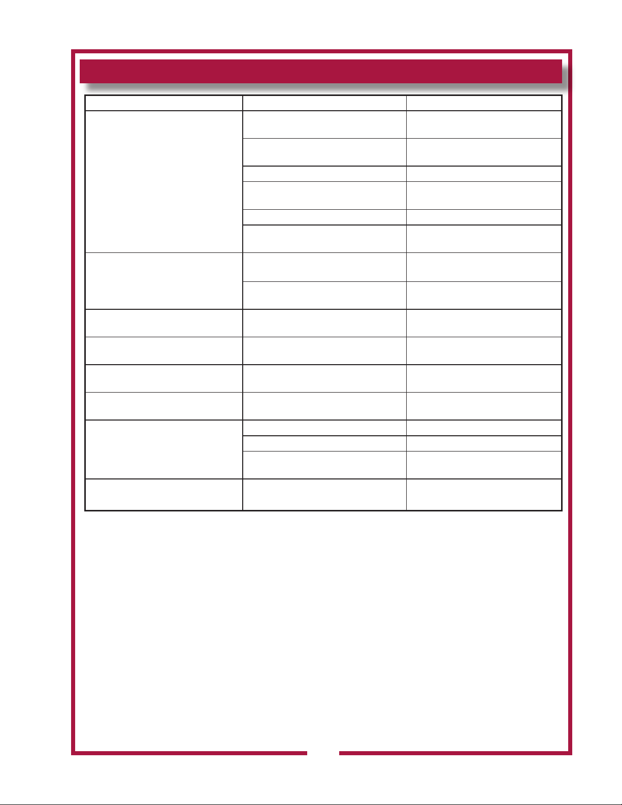
TROUBLESHOOTING SUGGESTIONS
DESCRIPTION POSSIBLE PROBLEM SUGGESTED REMEDY
Not plugged in or circuit breaker tripped
Fuse blown
Fryer will not heat
Fryer will not maintain temperature
Fryer leaks oil Damaged frypot
Element head will not raise
Element head will not stay in the up
position
Element head will not lower Damaged hinge bracket or support rod
Basket lift will not lower
Power switch not ON Press heat switch ON
Temperature control knob not set to
desired temperature
Hi-limit safety tripped Clean element
Damaged internal component
Temperature control thermostat
thermobulb contaminated with cooking
Damaged internal component
Frypot out of position, or has excess
cooking debris in bottom
Damaged hinge bracket or support rod
Timer not set Set to desired cook time
Timer “PUSH” button not pushed Push to start
Damaged internal component
Plug into proper receptacle. Reset
circuit breaker
Contact Wells Authorized Service
Agency for repairs
Set to desired temperature
1
, reset hi-limit
Contact Wells Authorized Service
Agency for repairs
Clean element
2
Contact Wells Authorized Service
Agency for repairs
Contact Wells Authorized Service
Agency for repairs
Check frypot for position, Clean frypot
Contact Wells Authorized Service
Agency for repairs
Contact Wells Authorized Service
Agency for repairs
Contact Wells Authorized Service
Agency for repairs
Basket lift will not raise Damaged internal component
1 The hi-limit safety is designed to shut down the fryer if the oil temperature exceeds 440ºF. A build-up of
cooking debris between the heating element and the thermobulb of the hi-limit safety will cause the hi-
limit to trip prematurely. Clean the element so that oil may circulate freely between the element and the
thermobulb. Reset the safety by pressing the red button on the bask of the element head.
2 A build-up of cooking debris between the heating element and the thermobulb temperature control
thermostat will cause inconsistent temperatures. Clean the element so that oil may circulate freely
between the element and the thermobulb.
304 p/n 2M-307591 Owners Manual Built-In Electric Autolift Fryers
Contact Wells Authorized Service
Agency for repairs
9
Page 12

MAINTENANCE
Periodic cleaning is
necessary to remove
carbonization from the
elements and frypot.
Frypot may be cleaned by
the method described at
right, or with a commercial
frypot cleaner. Be sure to
follow the manufacturer’s
directions.
Before cleaning, ALWAYS:
Disconnect the fryer
•
from electrical power
and allow to cool.
Drain the oil and wipe
•
out the frypot.
PERIODIC CLEANING
Add 1/2 cup of granulated dishwasher detergent to frypot. Fill with water
to the MAX OIL line.
Lower the element into the frypot and set the control knob to 225ºF
Boil the mixture for ve minutes. Turn the control knob to OFF. Allow the
mixture to set in the frypot overnight.
After the soak period, raise the elements and remove any remaining
carbonization with a stiff bristle brush. Be careful that the capillary tubes
of the thermobulbs are not moved or damaged during cleaning.
Drain the frypot and wash with warm water and mild detergent.
Reinstall the frypot in the fryer. Add 1 quart of vinegar, then ll to the MAX
OIL line with cold water.
Lower the elements into the vinegar solution. Allow to set for 15 minutes.
Drain the frypot and rinse with clean water. Dry the frypot and elements
thoroughly before returning the fryer to operation.
IMPORTANT: Nickel plated frypot must be dried completely in order to
prevent rusting, and to eliminate water contamination of the cooking oil.
10
304 p/n 2M-307591 Owners Manual Built-In Electric Autolift Fryers
Page 13
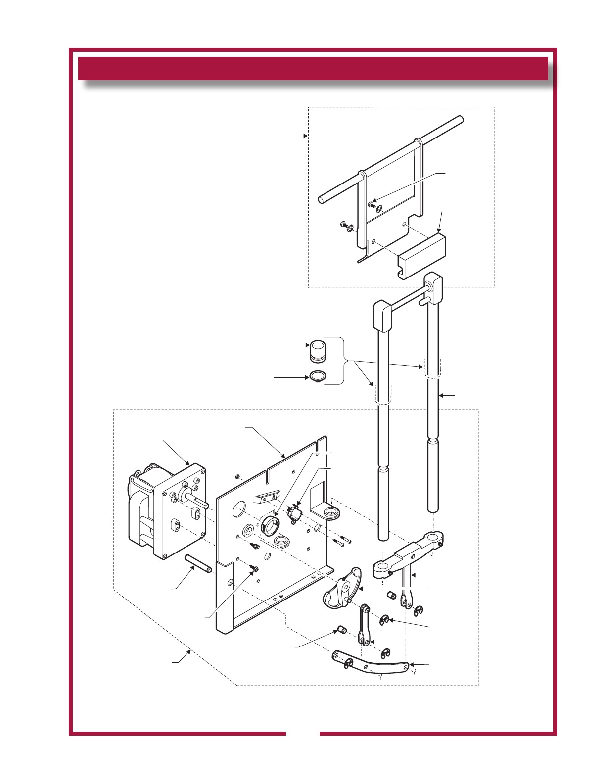
EXPLODED VIEW & PARTS LIST
E7-WL0035
E7-30543
2C-30222
E7-30878
2A-30876
2A-30207
2D-30215
2U-30233
2A-30205
2C-35530
4 places
2 places
2K-31040
E7-31259
2E-30198
WS-50231
2I-31145
2A-31146
2 places
2 places
WS-50850
2V-305658
2C-35487
Wells: Fryer Autolift Exploded View
IL1728 7/12/10
AUTOLIFT COMMON COMPONENTS
304 p/n 2M-307591 Owners Manual Built-In Electric Autolift Fryers
11
Page 14
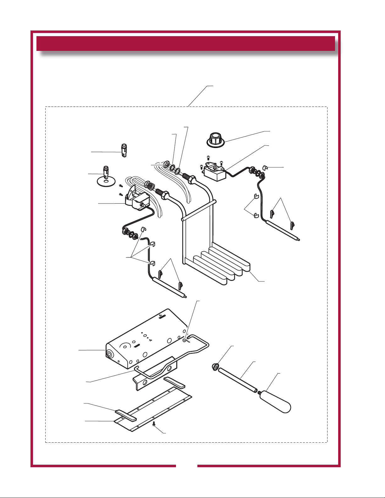
EXPLODED VIEW & PARTS LIST
WS-58656
2J-31157
2J-30516
2R-37882
2C-49689
2C-49689
2C-30157
2C-30157
2C-30157
WS-55510
2N-42842UL (208V)
2N-42866UL (240V)
red
amber
2C-30176
2I-Z12311
50172
fiber washer
RESET
WS-52427
2P-32428
E7-30464
DD-31202
hi-limit
temp control
2R-30211
2K-33358
2P-34452
lock washer
2C-35566
HEAD ASSY, COMPLETE, F586
WS-506902 (208V)
WS-506903 (249V)
2I-35747
IL2104, PL304
F586 BUILT-IN SINGLE-HEAD AUTOLIFT FRYER - FRY HEAD COMPONENTS
304 p/n 2M-307591 Owners Manual Built-In Electric Autolift Fryers
12
Page 15
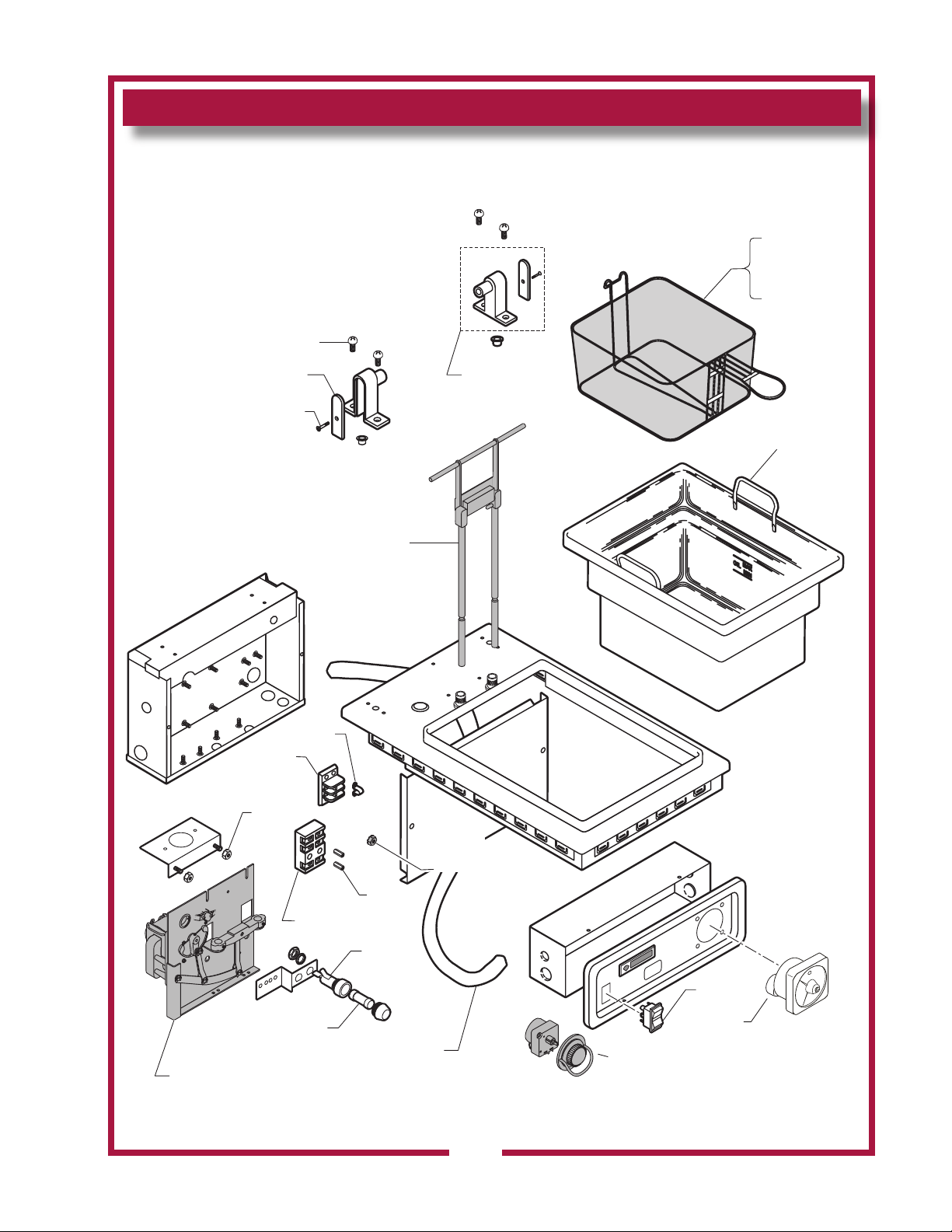
EXPLODED VIEW & PARTS LIST
2C-41974
2C-35736
green KEPS
2E-33068
2E-34005
WS-50131
1O-31881
sleeve
requires 3'
2D-301344
LIFT ASSEMBLY
see page 11
2E-34768
54769
WS-50183
2A-32806
2C-31717
2C-33890
2B-43688
2B-43689
1/2 size
full size
2C-31053
BASKET HOOKS
see page 11
2P-Z13854
PS-WL0159, F586
PS-WL0158, 586STS
2E-74098
WELLS
IL2105a, PL304
F586 BUILT-IN SINGLE-HEAD AUTOLIFT FRYER - CABINET COMPONENTS
304 p/n 2M-307591 Owners Manual Built-In Electric Autolift Fryers
13
Page 16
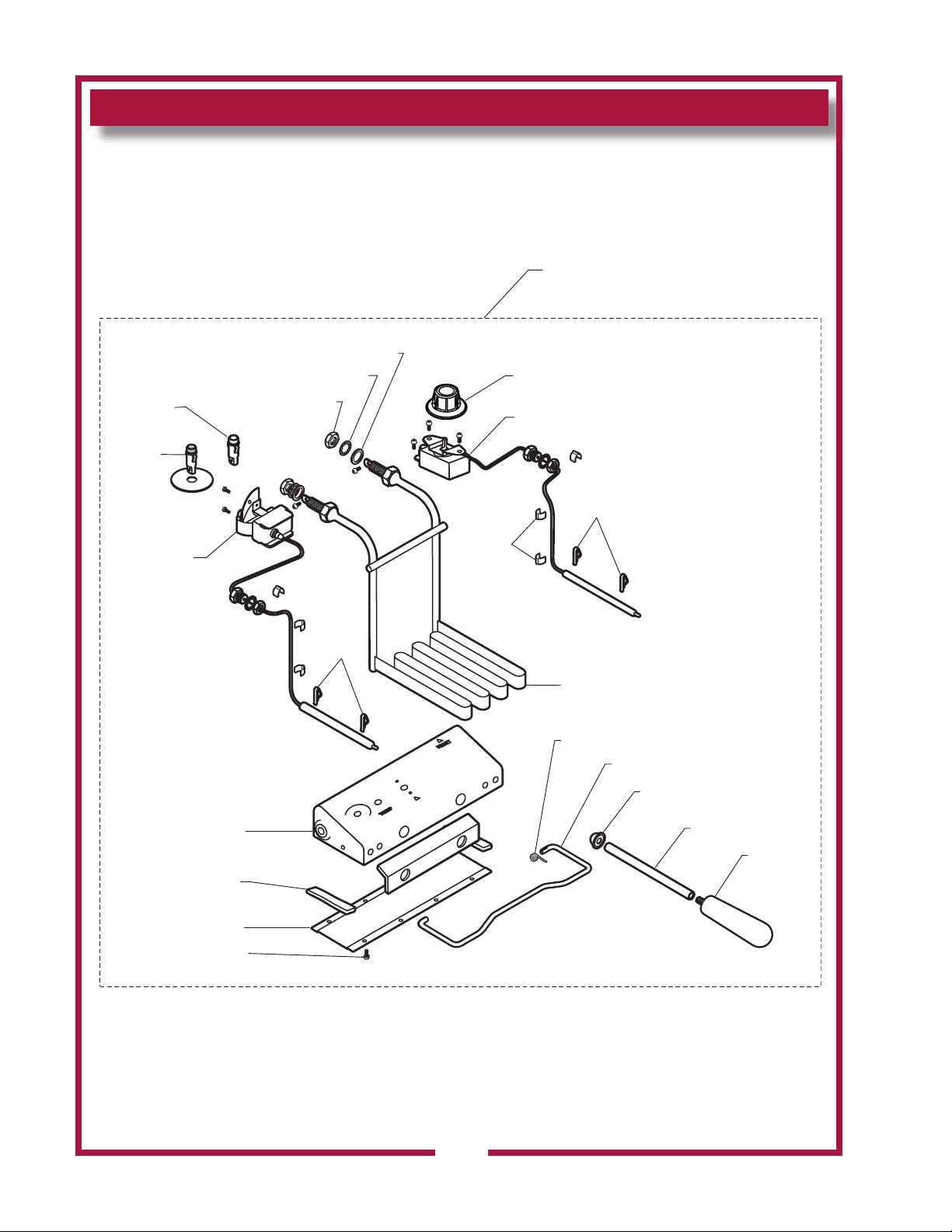
EXPLODED VIEW & PARTS LIST
RESET
2I-Z12311
WS-58656
2J-31157
2J-30516
2R-34066
2C-43665
2C-49689
2C-30157
2T-30133
2N-42892UL (240V)
2N-42891UL (208V)
amber
red
2C-30176
2C-30172
E7-34323
WS-52427
2P-32428
E7-30464
2R-30211
2K-33358
2P-34452
NOTE: Unit has two identical
fryer heads. Only one is shown.
lock washer
fiber washer
temp control
2C-35566
HEAD ASSY, COMPLETE, F-686
WS-62920 (208/240V)
2I-35747
IL2106
F686 BUILT-IN DUAL-HEAD AUTOLIFT FRYER - FRY HEAD COMPONENTS
14
304 p/n 2M-307591 Owners Manual Built-In Electric Autolift Fryers
Page 17
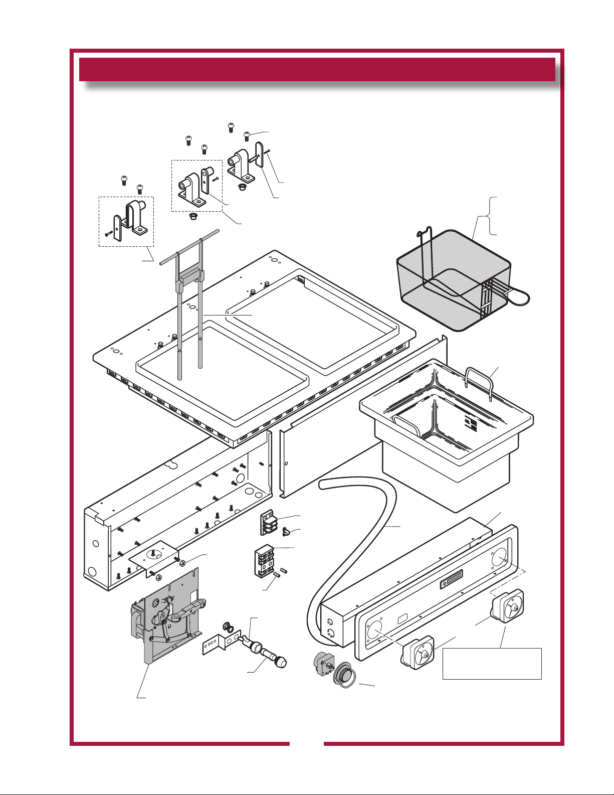
2D-301344
WS-50183
2A-32806
H6-33245
2C-31717
2C-33890
2C-31053
WS-50131
2C-41974
2E-33068
2E-34005
WS-53895
2B-43688
2B-43689
1/2 size
full size
BASKET HOOKS
see page 11
LIFT ASSEMBLY
see page 11
2E-34768
2E-34769
1O-31881
sleeve
requires 3'
2P-Z13854
Mfg Before 10/2010
PS-WL0152, 1 TIMER
PS-WL0151, 2 TIMERS
PS-WL0153, 1 Timer
PS-WL0146, 2 Timers
E7-Z13865
WELLS
IL2107a
EXPLODED VIEW & PARTS LIST
F686 BUILT-IN DUAL-HEAD AUTOLIFT FRYER - CABINET COMPONENTS
304 p/n 2M-307591 Owners Manual Built-In Electric Autolift Fryers
15
Page 18
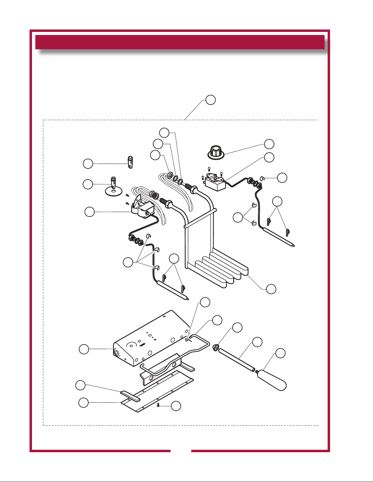
EXPLODED VIEW: F886
NOTE: Fryer has two identical
fryer heads. Only one is shown.
1
2
3
4
5
4
6
5
7
8
9
10
11
12
13
14
15
4
16
17
18
19
20
21
F886 BULT-IN DUAL-HEAD AUTOLIFT FRYER - FRY HEAD COMPONENTS
IL2053
304 p/n 2M-307591 Owners Manual Built-In Electric Autolift Fryers
16
Page 19
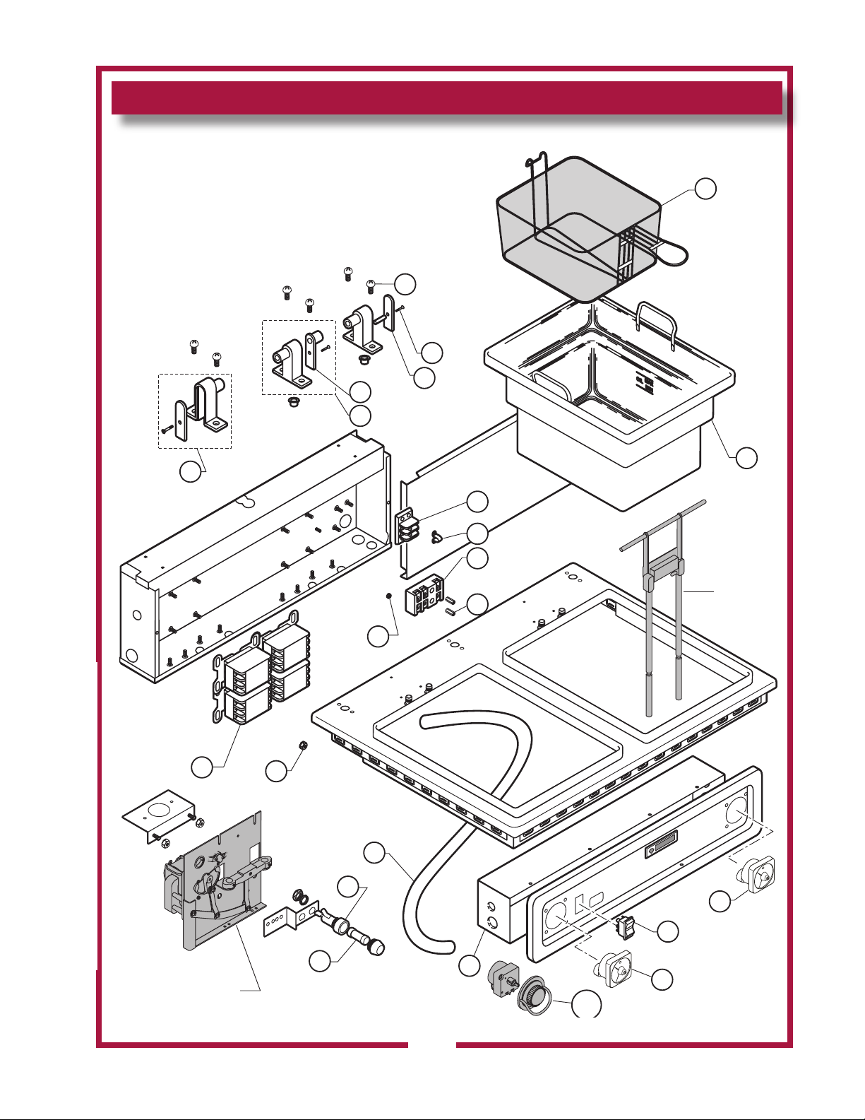
EXPLODED VIEW: F886
BASKET
HOOKS
2 places
see page 11
LIFT ASSEMBLY
2 places
see page 11
22
23
24
25
26
27
36
34
31
32
33
35
37
38
39
40
41
42
F886 BULT-IN DUAL-HEAD AUTOLIFT FRYER - CABINET COMPONENTS
IL2054a
29
28
28.1
30
28
304 p/n 2M-307591 Owners Manual Built-In Electric Autolift Fryers
17
Page 20
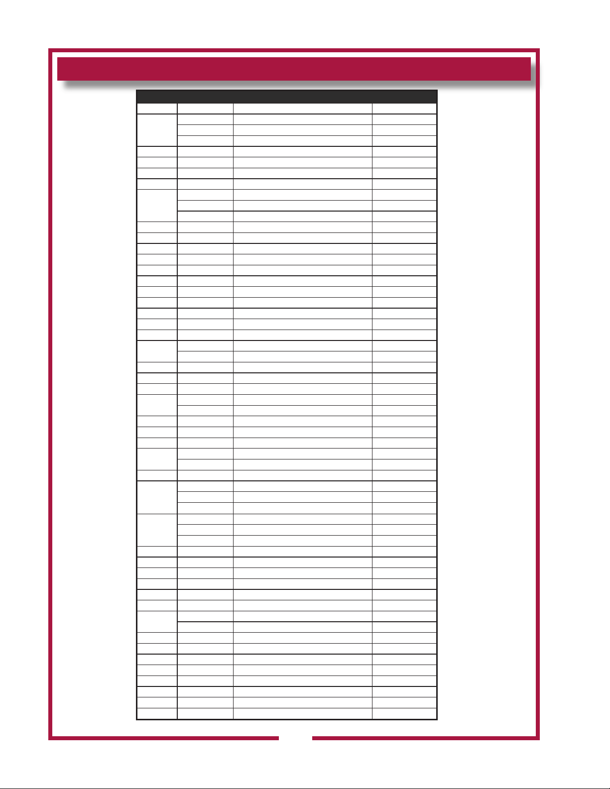
PARTS LIST: F886
Fig No Part No Description Application
1
2 2R-37882 KNOB CONTROL ASSY AUTOFRY
3 WS-55510 THERMO CTRL FRYER KP-715
4 2C-30157 CLIP CAPILLARY
5 2C-49689 CLMP BULB SS F49/F58RT
6
7 2P-32428 SPRING SUPPORT ROD FRYER
8 WS-52427 ROD SUPPORT SHORT HEAD
9 2P-34452 CAP PUSH ON TYPE BASKET
10 2K-33358 ADAPTER HANDEL
11 2R-30211 HANDLE LIFT GRAY
12 2C-35566 SCREW 6-32X1/4 PH TR HD
13 E7-35028 COVER CONTROL BOX WO/SAF14 2I-35747 GASKET DRWR RWS CLOSED
15 E7-30464 BOX CONTROL ASSY
16 WS-58656 HI-LIMIT MAN RESET 440F
17 2J-31157 LIGHT SIGNAL RED
18
19 2C-30172 NUT 7/8-14 HEX
20 2C-30176 WASHER LOCK FTG TUBE FRAM
21 2C-31777 WASHER LOCK 1/2 ID SEMS
22
23 2D-301344 POT, 15LB CAP
24 2E-33068 TERM BLOCK FLAME SENSOR
25 2E-34005 JUMPER FLAME SENSOR TERM
26
27 2C-41974 NUT 8-32 HEX 7/8 LONG ALU
28
28.1
29 2E-35127 SWITCH RKR PLSTC AMBER LT
30 E7-Z13865 CONTROL BOX
31 1O-31881 SLEEVING VARGLAS C-2 5/8
32 2E-34769 FUSEHLDR HPG-EE 10A 240V
33 2E-34768 FUSE SC-10 10A 300V
34 2C-31053 NUT 8-32 KEPS MS NICKEL
35
36 2C-35736 NUT 8-32 HEX KEPS MS GRN
37 WS-50183 HINGE BRACKET END
38 WS-53895 CTR PVT BRKT
39 H6-33245 COVER PIVOT DBL TUMBLE DE
40 2A-32806 COVER PIVOT BRKT TUMBLED
41 2C-31717 SCREW 8-32X7/8 PH FL
42 2C-33890 SCREW 12-24X3/4PH PAN
NI 2E-40873 TRANSFORMER 480V TO 240V 480V
F886 BUILT-IN DUAL-HEAD FRYER PARTS LIST
WS-62926 HEAD ASSY F88-6 208V STS 208V
WS-62927 HEAD ASSY F88-6 240V STS 240V
WS-62499 HEAD ASSY 480V F-856 480V
2N-42842UL ELEM 208V 5750W 208V
2N-42866UL ELEM 240V 5750W 240V
2N-42317UL ELEM 480V 5.75KW 480V
2J-30516 LIGHT SIGNAL AMBER
M3-WL0113 ASSY PILOT LIGHT AMBER 480V
2B-43688 BASKET WIRE TWIN
2B-43689 BASKET WIRE SINGLE
WS-50131 TERM BLK KIT -3 POLE, 85AMP 208/240V
2E-30252 TERM BLOCK 480V
PS-WL0152 1 TIMER REPLACEMENT KIT 48469
PS-WL0151 2 TIMER REPLACEMENT KIT 48469
2P-Z13854 TIMER 40MIN 240V 60HZ WFA Mfg After 10/2010
PS-WL0153 1 TIMER RETROFIT KIT 30227
PS-WL0147 2 TIMER RETROFIT KIT 30227
PS-WL0148 2 TIMER RETROFIT KIT 30227 WVF886
2E-Z14960 CONTACTOR, 40A 208/240COIL 208/240V
2E-303474 CONTACTOR 40A 4P 208-240V WVF886-400
304 p/n 2M-307591 Owners Manual Built-In Electric Autolift Fryers
18
Page 21
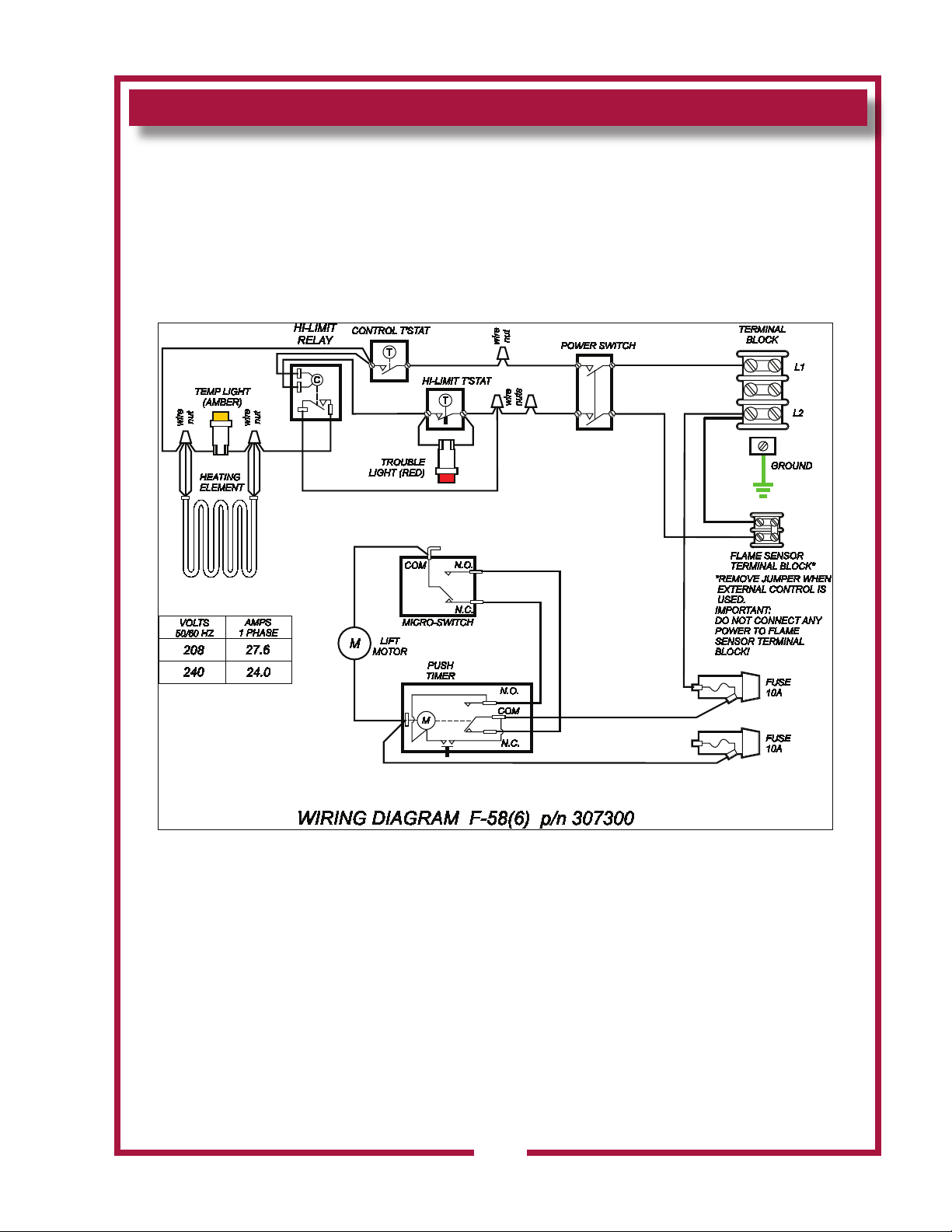
WIRING DIAGRAM
304 p/n 2M-307591 Owners Manual Built-In Electric Autolift Fryers
19
Page 22
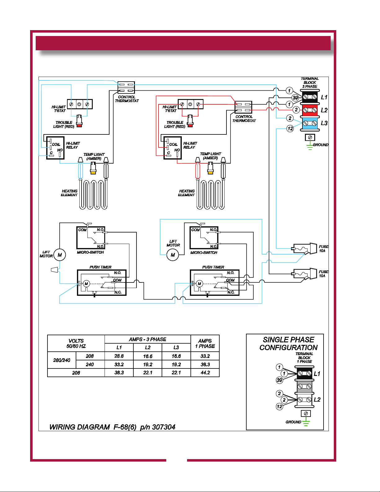
WIRING DIAGRAM
20
304 p/n 2M-307591 Owners Manual Built-In Electric Autolift Fryers
Page 23
WIRING DIAGRAM
304 p/n 2M-307591 Owners Manual Built-In Electric Autolift Fryers
21
Page 24

NOTES
22
304 p/n 2M-307591 Owners Manual Built-In Electric Autolift Fryers
Page 25

NOTES
304 p/n 2M-307591 Owners Manual Built-In Electric Autolift Fryers
23
Page 26

NOTES
24
304 p/n 2M-307591 Owners Manual Built-In Electric Autolift Fryers
Page 27
PARTS & SERVICE
DESCRIPTION PART NO.
FRY BASKET, HALF-SIZE 2B-43688
FRY BASKET, FULL SIZE 2B-43689
FRYPOT 2D-301344
CRUMB CRADLE WS-20690
COVER, FRYPOT E7-34421
IMPORTANT: Use only
factory authorized service parts
and replacement lters.
For factory authorized
service, or to order factory
authorized replacement parts,
contact your Wells authorized
service agency, or call:
Wells Bloomeld, LLC
10 Sunnen Dr.,
St. Louis MO 63143 USA
Service Dept.
phone: (314) 678-6314
fax: (314) 781-2714
Service Parts Department
can supply you with the name
and telephone number of
the WELLS AUTHORIZED
SERVICE AGENCY nearest
you.
CUSTOMER SERVICE DATA
please have this information available if calling for service
RESTAURANT _____________________________ LOCATION _____________
INSTALLATION DATE ________________________ TECHNICIAN ___________
SERVICE COMPANY ________________________________________________
ADDRESS ___________________________ STATE ______ ZIP__________
TELEPHONE NUMBER (_____)_____-_________
EQUIPMENT MODEL NO. _______________
EQUIPMENT SERIAL NO. _______________
VOLTAGE: (check one) 208 240 1ø 3ø
304 p/n 2M-307591 Owners Manual Built-In Electric Autolift Fryers
25
Page 28
WELLS BLOOMFIELD, LLC
10 Sunnen Dr., St. Louis, MO 63143
telephone: 314-678-6314
fax: 314-781-2714
www.wellsbloomfield.com
 Loading...