

Page 1

WELLS MANUFACTURING
265 Hobson Street, Smithville, Tennessee 37166
telephone: 314-678-6314
fax: 314-781-2714
www.wells-mfg
.com
OWNERS MANUAL
for
COUNTERTOP ELECTRIC
CHAR-BROILERS
Models:
B40
B44
161
Model B40
B50
includes:
INSTALLATION
USE and CARE
PARTS LISTS
WIRING DIAGRAMS
Model B50
IMPORTANT: DO NOT DISCARD THIS MANUAL
This manual is considered to be part of the appliance and is to be given to the OWNER or
MANAGER of the restaurant, or to the person responsible for TRAINING OPERATORS of
this appliance. Additional manuals are available from your WELLS DEALER.
THIS MANUAL MUST BE READ AND UNDERSTOOD BY ALL PERSONS USING OR
2M-303672 Rev. G
INSTALLING THIS APPLIANCE. Contact your WELLS DEALER if you have any
questions concerning installation, operation or maintenance of this equipment.
03/18
Page 2

161 2M-303672 OpManual for Countertop Electric Charbroilers
LIMITED EQUIPMENT WARRANTY
Wells Manufacturing warranties new products to be free from defects
in material and/or workmanship for a period of one [1] year from the
date of original installation, except as noted below. Defects that occur
as a result of normal use, within the time period and limitations defined
in this warranty, will at Wells’ discretion have the parts replaced or
repaired by Wells or a Wells-authorized service agency.
THIS WARRANTY IS SUBJECT TO ALL LISTED CONDITIONS.
Repairs performed under this warranty are to be performed by a Wellsauthorized service agency. Wells will not be responsible for charges
incurred or service performed by non-authorized repair agencies.
In all cases, the nearest Wells-authorized service agency must be used.
Wells will be responsible for normal labor charges incurred in the repair
or replacement of a warrantied product within 50 miles (80.5 km) of
an authorized service agency. Time and expense charges for anything
beyond that distance will be the responsibility of the owner. All labor
will need to be performed during regular service hours. Any overtime
premium will be charged to the owner. For all shipments outside the
U.S.A. and Canada, please see the International Warranty for specific
details.
It is the responsibility of the owner to inspect and report any shipping
damage claims, hidden or otherwise, promptly following delivery.
No mileage or travel charges will be honored on any equipment that is
deemed portable. In general, equipment with a cord and plug weighing
less than 50 lb. (22.7 kg) is considered portable and should be taken or
shipped to the closest authorized service agency, transportation prepaid .
CO NTAC T
Should you require any assistance regarding the operation or
maintenance of any Wells equipment; write, phone, fax or email
our service department. In all correspondence mention the
model number and the serial number of your unit, as well as
the voltage or type of gas you are using.
Business hours are 8:00 a.m. to 4:30 p.m. Central Standard Time
Telephone 314.678.6314
Fax 314.781.2714
Email customerservice@star-mfg.com
www.wells-mfg.com
WARRA
THE FOLLOWING WILL NOT BE COVERED UNDER WARRANTY.
• Any product which has not been installed, cleaned, maintained,
or used in accordance with the directions published in the appropriate
installation sheet and/or owner’s manual as well as national and local
codes, including incorrect gas or electrical connection. Wells is not liable
for any unit which has been mishandled, abused, misapplied, subjected
to chlorides, harsh chemicals, or caustic cleaners, damaged from
exposure to hard water, modified by unauthorized personnel, damaged
by flood, fire, or other acts of nature [or God], or which have an altered
or missing serial number.
• Installation, labor, and job checkouts, calibration of heat controls, air
and gas burner/bypass/pilot adjustments, gas or electrical system
checks, voltage and phase conversions, cleaning of equipment,
or seasoning of griddle surface.
• Replacement of fuses or resetting of circuit breakers, safety controls,
or reset buttons.
• Replacement of broken or damaged glass components, quartz heating
elements, and light bulbs.
• Labor charges for all removable parts in gas charbroilers and hotplates,
including but not limited to burners, grates, and radiants.
• Any labor charges incurred by delays, waiting time, or operating
restrictions that hinder a service technician’s ability to perform service.
• Parts that fail or are damaged due to normal wear or labor for
replacement of Items that can easily be replaced during a daily cleaning
routine. such as but not limited to silicone belts, PTFE non-stick sheets,
knobs, control labels, bulbs, fuses, quartz heating elements, baskets,
racks, and grease drawers.
• Components that should be replaced when damaged or worn, but have
been field-repaired instead [eg. field-welded fry pots].
• Any loss of business or profits.
ADDITIONAL WARRANTIES
Specialty/chain specific versions may also have additional and/or
extended warranties.
NTY EXCLUSIONS
PRODUCTS PARTS LABOR
universal ventless hoods 2 years 1 year
canopy hoods 2 years 1 year
“Cook’n Hold” equipment [HW10,
HWSMP, LLSC7, LLSC7WA, LLSC11,
2 years 1 year
an d LLSC 1 1WA]
cast iron grates, burners, and burner
shields
original Wells parts sold to repair
Wells equipment
1 year
90 days
The fore going warrant y is in lieu of any and a ll other warranti es expresse d or implied and c onstitutes the e ntire warranty. 2M-Z22393 • Rev A • 02.2018
Service First 1 year
Page 3
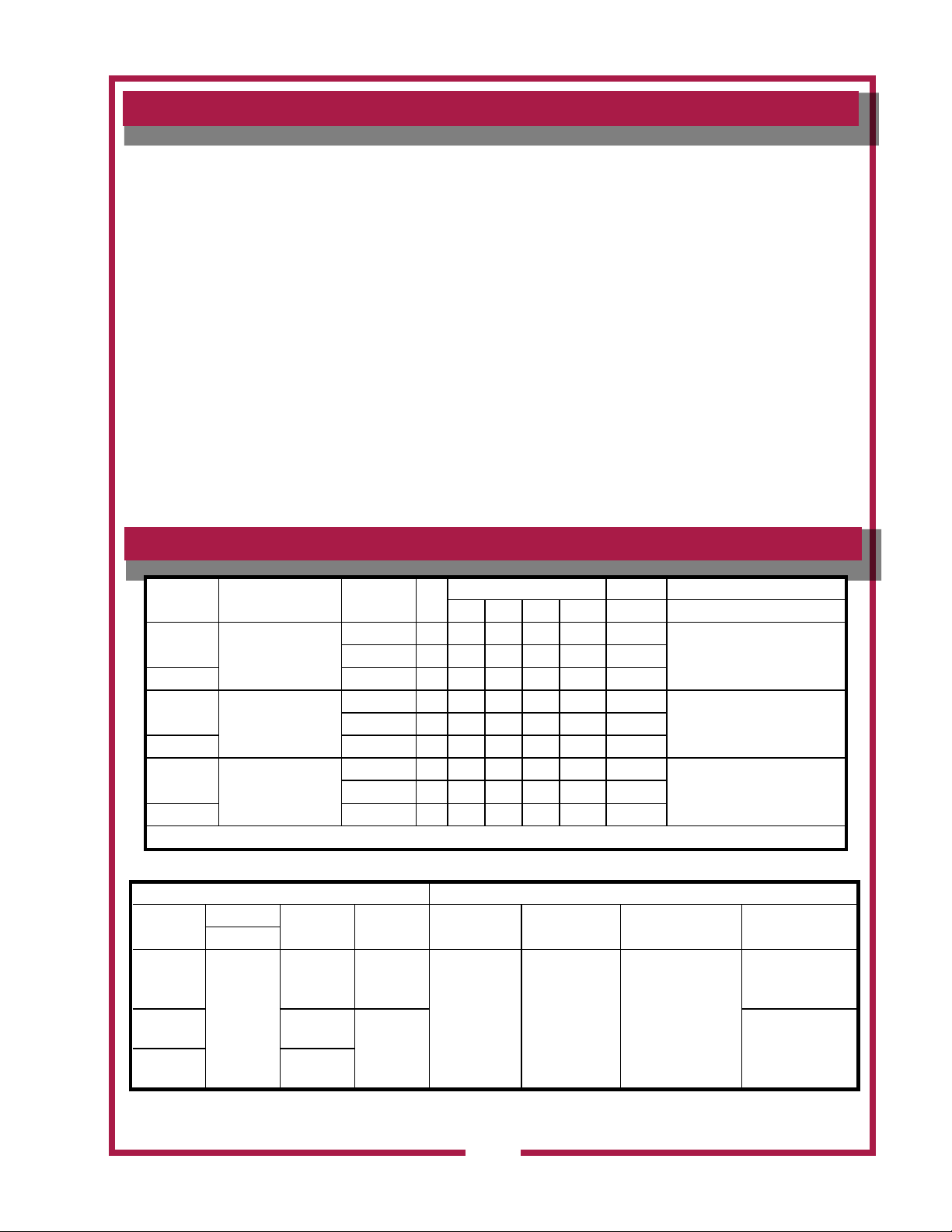
TABLE OF CONTENTS
WARRANTY
SPECIFICATIONS 1
FEATURES & OPERATING CONTROLS 2
PRECAUTIONS & GENERAL INFORMATION 4
AGENCY LISTING INFORMATION 4
INSTALLATION 5
OPERATION 7
SUGGESTED COOKING TIMES 9
CLEANING INSTRUCTIONS 10
TROUBLESHOOTING SUGGESTIONS 11
EXPLODED VIEW & PARTS LIST 12—17
WIRING DIAGRAM 18
PARTS & SERVICE 25
CUSTOMER SERVICE DATA 25
SPECIFICATIONS
MODEL ELEMENT VOLTS KW
B40
*B40EU 380-415 5.5 7.6 7.6 7.6 N/A
B44
*B44EU 380-415 5.5 7.6 7.6 7.6 N/A -
B50
*B50EU 380-415 11 15 15 15 N/A
SINGLE ASSEMBLY
SINGLE ASSEMBLY
DUAL ASSEMBLIES
208 5.5 12.9 12.9 22.4 N/A 26
208 5.5 11.5 22.4 14.4 N/A 26
208 11 30 30 30 N/A -
* for export model, also refer to European Operation Manual…, p/n 2M-301500
AMPS PER LEG 3Ø AMPS POWER
L1 L2 L3 NEUT. 1Ø CORD
Thank you for purchasing this
Wells Manufacturing appliance.
Proper installation, professional operation and consistent
maintenance of this appliance
will ensure that it gives you the
very best performance and a
long, economical service life.
This manual contains the information needed to properly install this appliance in a manner
which will ensure its optimum
performance.
OPTIONAL NEMA 6-30P 240 5.5 11.2 11.2 19.4 N/A 22.5
NOT SUPPLIED 240 5.5 10 19.5 12.5 N/A 22.5
NOT SUPPLIED 240 11 26 26 26 N/A 45
DIMENSIONS MINIMUM CLEARANCES
MODEL
B40
161 2M-303672 OpManual for Countertop Electric Charbroilers
B44
B50
HIGH
w/4” LEGS
15-3/8”
(39 CM)
WIDE DEEP BACK SIDE BOTTOM TOP
24-3/4”
(62.7 CM)
19-7/16”
(49.4 CM)
36-1/2”
(92.7 CM)
23-1/2”
(59.7 CM)
29-9/16”
(75.1 CM)
6”
(15.2 CM)
1
7”
(17.8 CM)
21”
(53.3 CM)
4”
(10.2 CM)
30”
(76.2 CM)
Page 4

161 2M-303672 OpManual for Countertop Electric Charbroilers
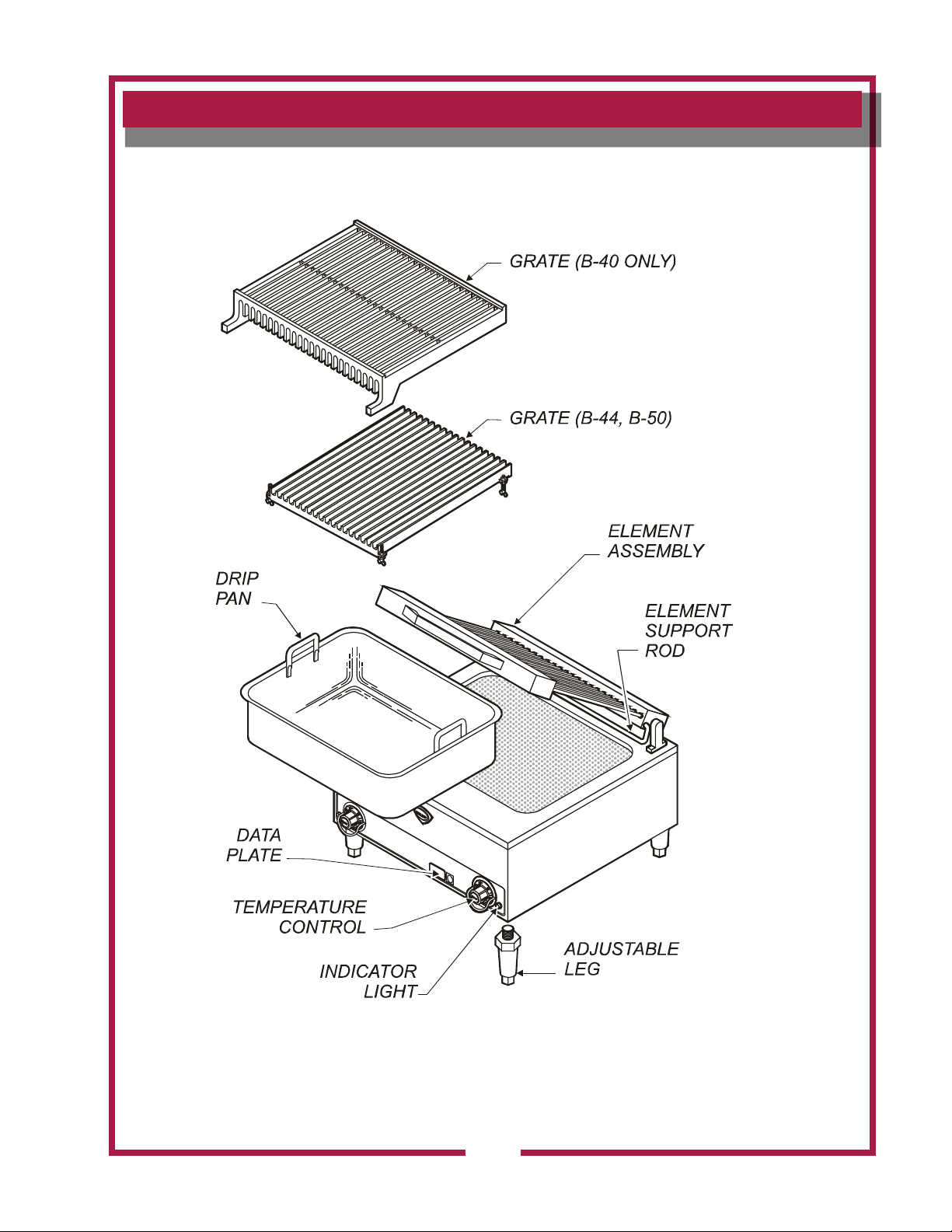
FEATURES & OPERATING CONTROLS
FEATURES & OPERATING DEFINITIONS
ITEM COMMENT
TEMPERATURE
CONTROL
INDICATOR LIGHT Light will glow when the innite switch is in any position other that OFF.
HEATING ELEMENT
GRATE
ELEMENT SUPPORT
ROD
DRIP PAN
DATA PLATE
ADJUSTABLE LEGS
The char-broiler is INFINITE SWITCH CONTROLLED. Power is applied to the heating elements based on
the control knob position and the amount of energy used.
The char-broiler element assembly may be raised for cleaning, or to add water to the drip pan. It is held
the “up” position by a support rod which automatically engages as the element is raised.
The grate is designed to protect the individual elements from food contact and spatula abrasion, resulting
in prolonged element life and reduced carbonization. The grate is easily removed for cleaning.
IMPORTANT: B-40 grate mounts above the element. B-44 and B-50 grates can mount above or below
the elements. Always remove a top-mounted grate before lifting the element assembly.
Hold element assembly in up position. Engages automatically when the element assembly is raised.
The heavy-duty removable drip pan is located under the element assembly. The drip pan catches food
particles and grease drippings
IMPORTANT: Remember to dis-engage the support rod before lowering element assembly.
IMPORTANT: DO NOT pour water over elements to rell drip pan.
During broiler operation. Maintain 2 inches of water in the drip pan at all times during operation of the
broiler. The drip pan is easily removed for cleaning.
Gives manufacturer, make, model and serial number. Also voltage and phase information, and agency
approvals.
The char-broiler is equipment with adjustable 4” legs.
Legs allow for:
a. leveling the broiler
b. ventilation around the broiler, and
c. cleaning the broiler
The supplied legs MUST be properly installed before the broiler is place into operation.
2
Page 5
FEATURES & OPERATING CONTROLS (continued)
161 2M-303672 OpManual for Countertop Electric Charbroilers
Fig. 1 Countertop Electric Charbroiler
IL2757
3
Page 6
161 2M-303672 OpManual for Countertop Electric Charbroilers
PRECAUTIONS AND GENERAL INFORMATION
WARNING:
Electric Shock
Hazard
All servicing requiring
access to non-insulated
electrical components must
be performed by a factory
authorized technician.
DO NOT open any access
panel which require the use
of tools. Failure to follow this
warning can result in severe
electrical shock.
CAUTION:
Risk of Damage
DO NOT connect or energize
this appliance until all installation instructions are read
and followed. Damage to the
appliance will result if these
instructions are not followed.
Broilers are intended for use to cook food products for human
consumption. No other use is recommended or authorized by the
manufacturer or its agents.
Broilers are intended for use in commercial establishments, where all
users are familiar with the appliance limitations, use and associated
hazards. Operating instruction and warnings must be read and
understood by all operators and users.
Do not submerge broilers in water. Do not splash, or pour water onto
controls, control panels or wiring.
Disconnect the broiler from electrical power before performing any
service or maintenance.
Allow drip pan to cool before removing from broiler. Do not operate
broiler without the drip pan installed. Do not operate the broiler without
2 inches of water in the drip pan.
Any parts replacement, maintenance procedure or servicing procedure
requiring the use of tools must be performed by an Authorized Service
Agency.
Any troubleshooting guides, component view, parts lists or installation
guides provided with this equipment are intended for the use of the
qualied technical personnel only.
Except where otherwise noted, this piece of equipment is made in the
USA and has American sizes on hardware.
This manual should be considered a permanent part of this appliance.
This manual and all supplied instructions, diagrams, schematics, parts
break downs, notices and labels must remain with the appliance if it
sold or moved to another location.
AGENCY LISTING INFORMATION
This appliance conforms to NSF Standard 4 for sanitation only if
installed in accordance with the supplied Installation Instructions.
STD 4
E6070 E6070
EXPORT
MODELS
ONLY
This appliance is and Listed under E6070.
Refer to installation instructions included with the broiler for
Underwriters Laboratories conditions of acceptability, electrical
requirements and other installation concerns.
Export versions only of this appliance meet standards.
4
Page 7
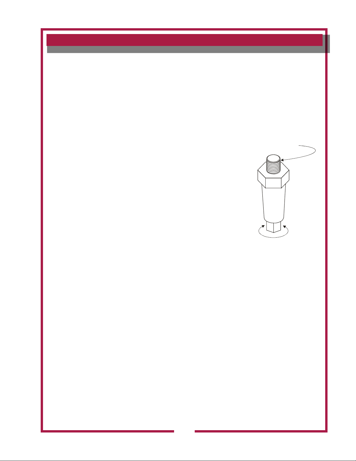
INSTALLATION
IL2758
SCREW INTO CABINET
MOUNTING HOLES
TURN TO
ADJUST HEIGHT
UNPACKING & INSPECTION
Carefully remove the appliance from the carton. Remove all protective
plastic lm, packing materials and accessories from the appliance
before connecting electrical power or otherwise performing any
installation procedure.
Carefully read all instructions in this manual and the Installation
Instruction Sheet packed with the appliance before starting any
installation.
Read and understand all labels and diagrams attached to the appliance.
Carefully account for all components and accessories before discarding
packing materials. Store all accessories in a convenient place for later
use.
SETUP
Setup the appliance only on a rm level surface. Non-combustible
material (e.g. metal, terrazzo) is recommended.
Supplied 4” legs must be properly installed and the broiler leveled.
(See Fig. 2) Move the broiler carefully to avoid damage to the legs.
Refer to the Installation Instruction Sheet for required clearances.
Maintain required clearances between the appliance and adjacent
combustible and non-combustible surfaces.
Sufcient overhead clearance must be provided to allow the element
assembly to be raised. Refer to the Installation Instruction Sheet for
required clearances.
Install drip pan and grate prior to heating and using broiler.
Avoid storing ammable or combustible materials near the appliance.
This includes gasoline and other fuels, mops, rags and wrapping paper.
NOTE: DO NOT discard
the carton or other packing
materials until you have
inspected the appliance for
hidden damage and tested it
for proper operation. Refer to
SHIPPING DAMAGE CLAIM
PROCEDURE on the inside
front cover of this manual.
Fig. 2 Adjustable Leg
161 2M-303672 OpManual for Countertop Electric Charbroilers
5
Page 8
161 2M-303672 OpManual for Countertop Electric Charbroilers
INSTALLATION (continued)
WARNING:
Risk of personal
injury
Installation procedures must
be performed by a qualied
technician with full knowledge
of all applicable electrical
codes. Failure can result in
personal injury and property
damage.
CAUTION:
Electrical Shock
Hazard
The broiler must be
electrically grounded.
Connect the terminal marked
“GND” or “ ” to a suitable
building ground.
IMPORTANT:
Contact a licensed electrician
to install and connect
electrical power the broiler.
Electrical installation must
be performed by a licensed
electrician in compliance with
all local ordinances and code
requirements.
ELECTRCAL HOOK-UP
Refer to the nameplate. Verify the electrical service power. Voltage
and phase must match the nameplate specications. Connecting the
griddle to the wrong voltage can severely damage the unit or cause
noticeable decreased performance.
Use copper wire suitable for a minimum of 90°C for electrical supply
connections.
Broilers are factory wired three-phase (3Ø). For single-phase (1Ø)
wiring, refer to the wiring diagram attached to the broiler. Conversion to
1Ø must be performed by a licensed electrician.
This broiler is not fused. Protect the circuit with properly sized fuses or
circuit breaker.
An electrical disconnect must be installed readily accessible to the
operator of the broiler.
IMPORTANT:
Damage due to being
connected to the wrong
voltage or phase is NOT
covered by warranty.
6
Page 9
OPERATION
HANDLE
ELEMENT
GRATE TANG
FRONT
IL2760
PREPARE THE CHAR-BROILER
FOR USE
When using the broiler for the rst
time, wipe the entire unit with a
clean damp cloth or sponge and mild
detergent. Rinse thoroughly clean
water. Dry with a soft clean cloth.
Remove the GRATE and raise the
ELEMENT ASSEMBLY.
Install the DRIP PAN and add 2
2 inches (5cm) of tap water.
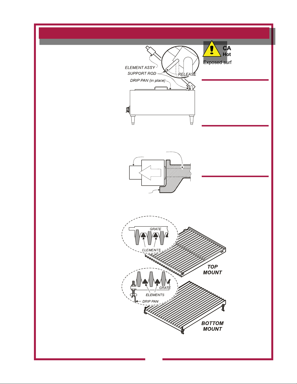
Release the ELEMENT SUPPORT
ROD by lifting the element assembly
slightly, then pulling the lower portion
of the support rod forward. Lower
the ELEMENT ASSEMBLY gently.
MODEL B-40: Grate must be
installed ABOVE elements.
Install the GRATE, front edge rst.
The TANGS of the grate go DOWN
and point toward the FRONT. The
grooves on the underside of the
grate align with the elements. The
rear edge of the grate can be
lowered until it rests rmly on the
elements.
IL2759
Fig. 3 ELEMENT SUPPORT ROD
Fig. 4 B-40 GRATE INSTALLATION
CAUTION:
Hot Surface
Exposed surfaces can be hot
to the touch and may cause
burns.
IMPORTANT:
DO NOT attempt to raise the
element assembly without
rst removing the grate.
Damage to the hinges will
result. Such damage is NOT
covered by warranty.
IMPORTANT:
Allow drip pan to cool before
removing from the broiler.
DO NOT operate the broiler
without the drip pan installed.
DO NOT operate the broiler
without 2” (5cm) of water in
the drip pan.
IMPORTANT:
DO NOT attempt to lower the
element assembly without
rst releasing the support rod.
Damage to the hinges will
result. Such damage is NOT
covered by warranty.
MODELS B-44 and B-50: Grate(s)
can be installed above or below the
elements.
ABOVE: Gently lower grate over
elements. The end with ush tabs
goes toward the front.
BELOW: Install one wing bolt in
each tab. The notch in the wing
rests on the lip of the drip pan. The
end with ush tabs must go toward
the front Adjust the wing bolts so
161 2M-303672 OpManual for Countertop Electric Charbroilers
that , when the element assembly
is lowered, the top of the element
is 1/4” (6mm) below the top of the
grate ns.
IL2761
Fig. 5 B-44 and B-50 GRATE INSTALLATION
7
Page 10

161 2M-303672 OpManual for Countertop Electric Charbroilers
OPERATION (continued)
CAUTION:
Hot Surface
IL2762
Fig. 6 TEMPERATURE CONTROL
Exposed surfaces can be hot
to the touch and may cause
burns.
IMPORTANT: DO NOT
POUR WATER OVER
ELEMENTS TO REFILL PAN.
DO NOT splash or pour water
onto controls, control panels
or wiring.
TEMPERATURE CONTROLS
Each section of the broiler is equipped with an individual temperature
control. The desired temperature is controlled by rotating the
TEMPERATURE CONTROL KNOB. Any time the control is turned
“ON”, the adjacent indicator light will glow. Each section of the broiler
may be set to a different temperature setting.
“OFF” removes power from the element., allowing the element to cool.
Use OFF to turn the broiler off at the end of the cooking day.
“LO” is the lowest temperature settings. Use LO for stand-by operation.
“2” thru “8” are temperature settings. Higher number indicate higher
temperature.
“HI” is a continuous ON setting. Use HI for pre-heating the broiler.
USING THE CHAR-BROILER
Pre-Heat the broiler ten (10) minutes by turning the TEMPERATURE
CONTROL to “HI”.
After the pre-heat period, turn the TEMPERATURE CONTROL to the
desired setting (refer to the Broiler Chart at right for recommended
settings).
After every order, use the brush provided to brush any remaining food
particles from grate and elements. Keeping the cooking surfaces clean
will help in maintaining food taste.
Visually check the water level in the drip pan during operation. Add
water as required to maintain 2” (5cm) water depth in the drip pan.
8
Page 11

OPERATION (continued)
BROILER CHART
RECOMMENDED COOKING TIMES AND DIAL SETTINGS
NOTE: The times and dial settings in this chart are suggestions only. Your own experience with your
own menu items will be your best guide to achieving the best food product.
PRODUCT
Condition SETTING Minutes Total
THICKNESS
COOKING
DIAL
TIME
BEEF Frozen 1/2” Rare 8 4 -6
“ 1/2” Medium 8 7 - 9
“ 3/4” Rare 7 7 - 9
“ 3/4” Medium 7 8 - 10
“ 1” Rare 7 12 - 14
“ 1” Medium 7 14 - 16
“ 1-1/4” Rare 6 23 - 25
“ 1-1/4” Medium 6 25 - 27
BEEF Non-Frozen 3/4” Rare HI 4 - 6
3/4” Medium HI 5 - 7
1” Rare HI 7 - 9
1 Medium HI 8 - 10
1-1/4” Rare HI 12 - 14
1-1/4” Medium HI 13 - 15
1-1/2” Rare HI 14 - 16
1-1/2” Medium HI 18 - 20
161 2M-303672 OpManual for Countertop Electric Charbroilers
9
Page 12

161 2M-303672 OpManual for Countertop Electric Charbroilers
CLEANING INSTRUCTIONS
CAUTION:
Electric Shock
Hazard
Disconnect appliance
from electric power before
cleaning.
CAUTION:
Burn Hazard
Allow appliance to cool
completely before cleaning.
CAUTION:
Electric Shock
Hazard
Do not submerge appliance
in water.
IMPORTANT: DO NOT spill
or pour water into controls,
control panel or wiring.
PREPARATION
Turn both temperature control knobs OFF.
Allow broiler to cool completely.
Disconnect broiler from electric power.
FREQUENCY
Daily.
TOOLS
Steel Brush with scraper
Plastic Scouring pad, Soft-Bristled Fiber Brush
Mild Detergent, Non-Abrasive Cleanser
Clean Soft Cloth / Sponge
CLEANING
1. Remove the grate from the broiler. Clean grate
a. Use the supplied steel brush with scraper to remove
food particles and residue from grate surfaces.
b. Grate may be washed in sink or dishwasher.
c. Dry the grate and apply a light coating of cooking oil.
DO NOT submerge broiler
in water. Damage to
internal components will
occur. Damage to internal
components from water
damage is not covered by
warranty.
2. Raise the element assembly until it latches. Remove and
clean the drip pan:
a. Stubborn food particles maybe removed with a
plastic scouring pad.
b. Drip pan may be washed in a sink or dishwasher.
3. Clean the element assembly:
a. Use a soft-bristled ber brush to remove any remaining food
particles from the elements.
b. Clean the element rods with a soft damp cloth or sponge and
mild detergent. Rinse by wiping with a soft cloth moistened
with clean water. Dry with a soft cloth.
4. Clean broiler cabinet:
a. Use a plastic scouring pad to remove any remaining food
particles from the cabinet.
b. Clean the cabinet with a soft damp cloth or sponge and mild
detergent. Rinse by wiping with a soft cloth moistened with
clean water. Dry with a soft cloth.
5. Reassemble broiler:
a. Reinstall drip pan.
b. Unlatch element support rod and carefully lower the element
assembly.
c. Reinstall the grate.
Procedure complete
10
Page 13

SYMPTON POSSIBLE CAUSE SUGGESTED REMEDY
Won’t heat - - no indicator lights
One or more section won’t
heat—or not hot enough
One or more section too hot
Element assy loose, or difcult to
raise or lower
Element assy does not latch in up
position
TROUBLESHOOTING SUGGESTIONS
Not plugged in, or Check plug
Circuit breaker tripped. Check / reset circuit breaker
Temperature control not set Set temperature control knob to desired temperature
240V unit run on 208V Verify proper voltage
Damaged component or wiring
Temperature control not set Set temperature control knob to desired temperature
208V unit run on 240V Verify proper voltage
Damaged component or wiring
Damaged hinge
(see page 7 for precautions)
Damaged support rod assembly
Contact an Authorize Wells Service Agency for
repairs
Contact an Authorized Wells Service Agency for
repairs
Contact an Authorized Wells Service Agency for
repairs
Contact an Authorized Wells Service Agency for
repairs
There are no user-serviceable
components in this unit.
In all instances of damage or
malfunction, contact your
Authorized Wells Service
Agency for repairs.
161 2M-303672 OpManual for Countertop Electric Charbroilers
11
Page 14

161 2M-303672 OpManual for Countertop Electric Charbroilers
EXPLODED VIEW & PARTS LIST
Model: B40 Electric Charbroiler
WELLS
1
2
3
6
7
8
9
10
11
IL1728 Rev. B 4/20/12
14
20
21
19
18
15
16
17
12
13
4
5
PL161
COUNTERTOP ELECTRIC
CHAR BROILER
MODEL B-40
12
Page 15

EXPLODED VIEW & PARTS LIST
B40 Electric Charbroiler
Fig No Part No Qty Description Application
1 WS-21707 1 BROILER GRATE B40/B406
2 H6-32728 1 COVER RR ELEM ASS
3 WS-57509 1 CASTING ASSY ELEM REAR
4 WS-52729 1 ROD SUPPORT B40 406
5 2P-32428 1 SPRING SUPPORT ROD
6 H6-35594 1 PAN GREASE B40
7 2A-32840 1
2E-37465
8
2E-40310 TERM BLOCK 4POLE 75AMP B40-400V
9 2A-32841 1
10 2A-32806 2 COVER PIVOT BRKT
2A-Z0314
11
2A-30586 FEET ADJ 4” GRAY PLASTIC
12 H6-Z12082 2 BASE, SHELL
13 2M-300534 1 TRADEMARK DOMED LABEL
14 2R-30371 2 KNOB ASSY WARMERS
15 D8-30256 2 TRIM RING ASSY
16 2E-34593 2 SW INF 240V B CAM 13/16S
17 2J-30516 2 LIGHT SIGNAL AMBER M3938P
WS-500686
18
2R-300666 HANDLE BROILERS DIE CASET
19 WS-57508 1 CASTING ASSY ELEM FRONT
WS-52722
20
WS-52723 ELEM ASSY 240V B40 / B406
DD-503811 ELEM ASSY B40EU 220/380V B40-400V
WS-50007
21
WS-50005 ELEM 120V 225W BROILER B40-240V
2N-303805 ELEM 110V 225W BROILER B40-400V
L PIVOT BRKT (use mount screw 2C-33890)
TERM BLOCK 3 POLE 85AMP 208/240V
1
R PIVOT BRKT (use mount screw 2C-33890)
FEET 4” DIE CAST.
4
KIT HANDLE B40/B406
1
ELEM ASSY 208V B40 / B406
1
ELEM 104V 225W BROILER B40-208V
24
161 2M-303672 OpManual for Countertop Electric Charbroilers
13
Page 16

161 2M-303672 OpManual for Countertop Electric Charbroilers
EXPLODED VIEW & PARTS LIST
Model: B44 Electric Charbroiler
IL1729 Rev. A 4/14/09
PL161
WELLS
1
2
3
4
5
6
7
8
9
10
11
12
13
15
16
17
18
19
20
21
2223
14
COUNTERTOP ELECTRIC
CHAR BROILER
MODEL B-44
14
Page 17

EXPLODED VIEW & PARTS LIST
B44 Electric Charbroiler
Fig No Part No Qty Description Application
1 H6-38623 1 GRATE AS RECD BROILER
2 H6-32740 1 COVER RR ELEM ASSY B44
3 WS-57507 1 CASTING ASSY ELEM REAR
4 2P-32428 1 SPRING SUPPORT ROD
5 2A-34061 1 ROD HEAD SUUORT B44/B446
6 H6-35593 1 PAN GREASE B44-50
7 2A-32840 1
8 2A-32841 1
9 2A-32806 2 COVER PIVOT BRKT
10 E7-37893 1 COVER ACCESS F101 ROHS
11 2E-Z14960 1 CONTACTOR 40A 208/240COIL
12
13 DD-52128 1 TUBING TIMER WIRES F3672
14
15 2J-30516 2 LIGHT SIGNAL AMBER M3938P
16 2R-30371 2 KNOB ASSY WARMERS
17 D8-30256 2 TRIM RING ASSY
18 2E-34593 2 SW INF 240V B CAM 13/16S
19 2M-300534 1 TRADEMARK DOMED LABEL
20
21 WS-57506 1 CASTING ASSY ELEM FRNT
22
23
NI 2E-35635 2 CAPCTR, .015
WS-50131
2E-4310 TERM BLOCK 4POLE 75AMP B44-400
2A-Z0314 4 FEET 4” DIE CAST.
2A-30586 4 FEET ADJ 4” GRAY PLASTIC
WS-500687 1 KIT HANDLE B44/446 B50/506
2R-300666 1 HANDLE BROILERS DIE CASTE
WS-52737
WS-52738 ELEM ASSY 240V B44,50 BASE
H6-303816 ELEMENT ASSY B44 EU B44-400
WS-50020
WS-50019 ELEM 115V 300W BROILER
2N-303802UL ELEM 110W 300W BROILER B44-400
1
1
18
L PIVOT BRKT (use mount screw 2C-33890)
R PIVOT BRKT (use mount screw 2C-33890)
TERM BLK KIT 3-POLE 85AMP 208/240
ELEM ASSY 208V BASE B44, B50
ELEM 104V 300W BROILER
161 2M-303672 OpManual for Countertop Electric Charbroilers
15
Page 18

161 2M-303672 OpManual for Countertop Electric Charbroilers
EXPLODED VIEW & PARTS LIST
WELLS
Model: B50 Electric Charbroiler
IL1730 Rev. C 7/27/11
PL161
1
2
3
4
5
6
7
8
9
11
12
13
14
14
15
17
18
19
20
21
22
2324
16
10
COUNTERTOP ELECTRIC
CHAR BROILER
MODEL B-50
16
Page 19

EXPLODED VIEW & PARTS LIST
B50 Electric Charbroiler
Fig No Part No Qty Description
1 H6-38623 2 GRATE MACH BROILER ASSY
2 H6-32740 2 COVER RR ELEM ASSY B44, B50
3 2E-30001 30 JUMPER, ELEMENT LONG
4 2E-30002 18 JMPR-ELEMENT,1-1/4” BRLR
5 WS-57507 2 CASTING ASSY ELEM REAR
6 2P-32428 2 SPRING SUPPORT ROD
7 2A-32741 2 ROD HEAD SUPPORT ASSY
8 H6-35593 2 PAN GREASE B44-50
9 2A-32840 2
10 H6-33245 1 COVER DOUBLE PIVOT BRKT
11 2E-Z14960 1 CONTACTOR 40A 208/240COIL
12 WS-50131 2 TERM BLK KIT 3-POLE 85AMP
13 2A-32841 1
14 2A-32806 2 COVER PIVOT BRKT TUMBLED
15
16 2M-300534 1 TRADEMARK DOMED LABEL
17 2R-30371 2 KNOB ASSY WARMERS
18 D8-30256 2 TRIM RING ASSY
19 2E-34593 2 SW INF 240V B CAM 13/16S
20 2J-30516 2 LIGHT SIGNAL AMBER
21
22 WS-57506 1 CASTING ASSY ELEM FRNT
23
24
NI 2E-35635 2 CAPCTR, .015
NI 2A-33038 4 FEET ADJ BROILER GRATES
2A-Z0314 4 FEET 4” DIE CAST.
2A-30586 4 FEET ADJ 4” GRAY PLASTIC
WS-500687
2R-300666 HANDLE BROILERS DIE CASTE
WS-52737
WS-52738 ELEM ASSY 240V B44, B50
WS-50020
WS-50019 ELEM 115V 300V BROILER
2
2
36
L PIVOT BRKT (use mount screw 2C-33890)
R PIVOT BRKT (use mount screw 2C-33890)
KIT HANDLE B44/446 B50/506
ELEM ASSY 208V B44, B50
ELEM 104V 300W BROILER
161 2M-303672 OpManual for Countertop Electric Charbroilers
17
Page 20

161 2M-303672 OpManual for Countertop Electric Charbroilers
EXPLODED VIEW & PARTS LIST
CONTROL KNOB IDENTIFICATION
All versions of the Wells Electric Char-Broiler use control knob p/n 2R-30371.
IL2763
18
Page 21

WIRING DIAGRAM
161 2M-303672 OpManual for Countertop Electric Charbroilers
19
Page 22

161 2M-303672 OpManual for Countertop Electric Charbroilers
WIRING DIAGRAM
20
Page 23

WIRING DIAGRAM
161 2M-303672 OpManual for Countertop Electric Charbroilers
21
Page 24

161 2M-303672 OpManual for Countertop Electric Charbroilers
WIRING DIAGRAM
22
Page 25

NOTES
161 2M-303672 OpManual for Countertop Electric Charbroilers
23
Page 26

161 2M-303672 OpManual for Countertop Electric Charbroilers
NOTES
24
Page 27

PARTS & SERVICE
DESCRIPTION SERVICE
PART NO.
CORDSET 240V 30A NEMA 6-30P,
B-40, B-44 2E-35259
GREASE PAN, B-44 (1 PER UNIT)
B-50 (2 PER UNIT) H6-35593
GREASE PAN, B-40 H6-35594
LEGS, 4”, METAL SET OF 4 2A-Z0314
GRATE, B-44 (1 PER UNIT)
B-50 (2 PER UNIT) H6-38623
GRATE, B-40 WS-21707
BRUSH, BROILER 2P-30013
IMPOR TANT: Use only factory
authorized service parts and
replacement
For factory authorized service,
or to order factory authorized
replacement parts, contact your
Wells authorized service agency,
or call:
Wells Manufacturing
10 Sunnen Dr.
Smithville, Tennessee 37166 U.S.A.
Service Dept.
phone: (314) 678-6314
fax: (314) 781-2714
Service Parts Department
can supply you with the name
and telephone number of
the WELLS AUTHORIZED
SERVICE AGENCY
nearest you.
lters.
CUSTOMER SERVICE DATA
please have this information available if calling for service
RESTAURANT _____________________________ LOCATION _____________
INSTALLATION DATE ________________________ TECHNICIAN ___________
SERVICE COMPANY ________________________________________________
ADDRESS ___________________________ STATE ______ ZIP__________
TELEPHONE NUMBER (_____)_____-_________
EQUIPMENT MODEL NO. ______________ EQUIPMENT SERIAL NO. _______________
VOLTAGE: (check one) 208 240 480
161 2M-303672 OpManual for Countertop Electric Charbroilers
25
Page 28

WELLS MANUFACTURING
265 Hobson Street, Smithville, Tennessee 37166
telephone: 314-678-6314
fax: 314-781-2714
www.wells-mfg
.com
 Loading...