

Page 1
WP3066ADAM User’s Manual V1.42A
WP3066ADAM
User’s Manual
Version 1.42A
Shanghai Wellpro Electrical Technology Co., Ltd.
www.shwellpro.com
Page 2
WP3066ADAM User’s Manual V1.42A
1、Product description
⚫ Eight temperature input channel: DS18B20 sensor
⚫ RS485 MODBUS RTU standard communication protocol
⚫ Netted with configuration software, PLC or industry touch panel
⚫ Communication status LED
⚫ Communication circuit designed for thunder protection and interference immunity
⚫ Used for signal collection and control in industrial field
2、Specification
⚫ Temperature input channel 8ch (DS18B20 sensor)
⚫ Temperature input range -55~125℃
⚫ Temperature input accuracy ±0.5℃
⚫ Temperature input resolution 0.1℃
⚫ Effective connection distance ≤25 meters (normal cable for sensor)
⚫ Working temperature -20~70℃
⚫ External power supply DC9V~30V/2W
⚫ Installation method Standard DIN slide rail or screw
⚫ Dimension 125×73×35mm
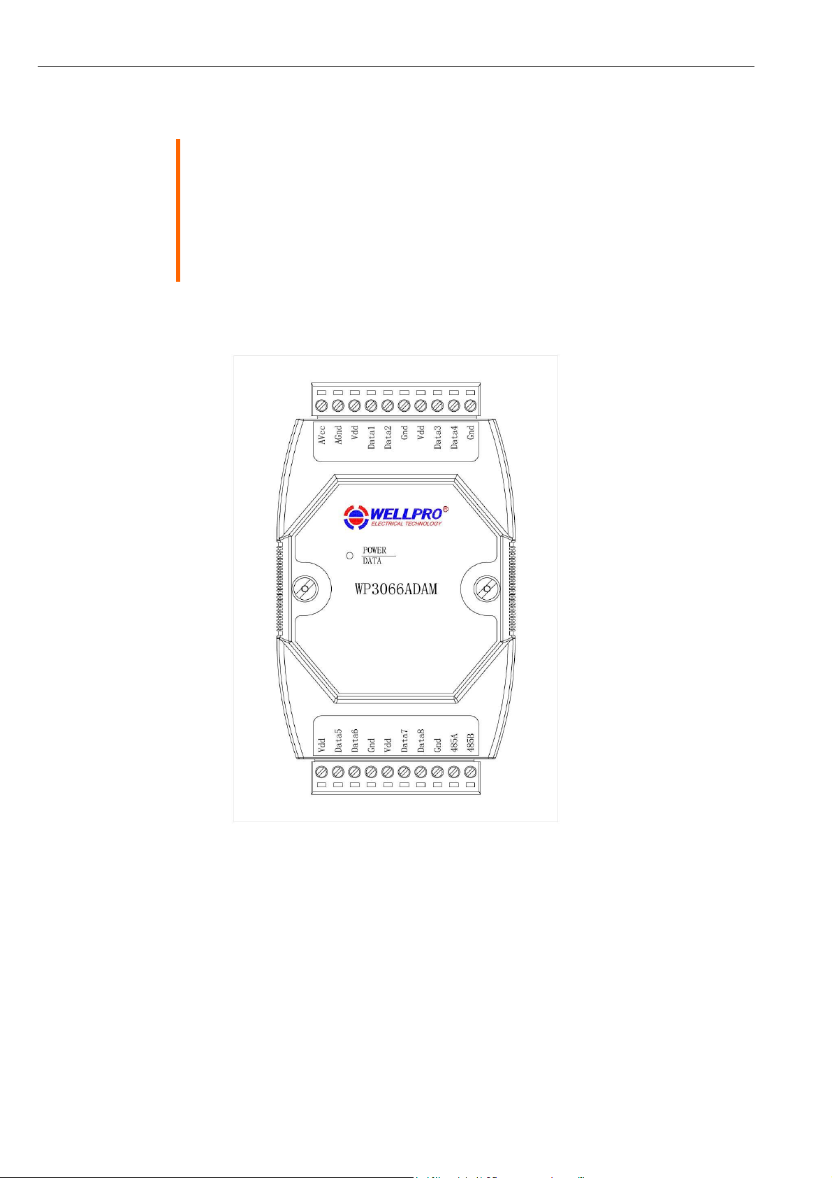
3、Interface description
AVcc
External power supply input positive
AGnd
External power supply input negative / Power ground
Vdd
DS18B20 pin Vdd / +5V
Data1
DS18B20 channel 1 pin DQ
Data2
DS18B20 channel 2 pin DQ
Gnd
DS18B20 pin Gnd / 0V
Vdd
DS18B20 pin Vdd / +5V
Data3
DS18B20 channel 3 pin DQ
Data4
DS18B20 channel 4 pin DQ
Gnd
DS18B20 pin Gnd / 0V
Vdd
DS18B20 pin Vdd / +5V
Data5
DS18B20 channel 5 pin DQ
Data6
DS18B20 channel 6 pin DQ
Gnd
DS18B20 pin Gnd / 0V
Vdd
DS18B20 pin Vdd / +5V
Data7
DS18B20 channel 7 pin DQ
Data8
DS18B20 channel 8 pin DQ
Gnd
DS18B20 pin Gnd / 0V
485B
RS485 signal B-
485A
RS485 signal A+
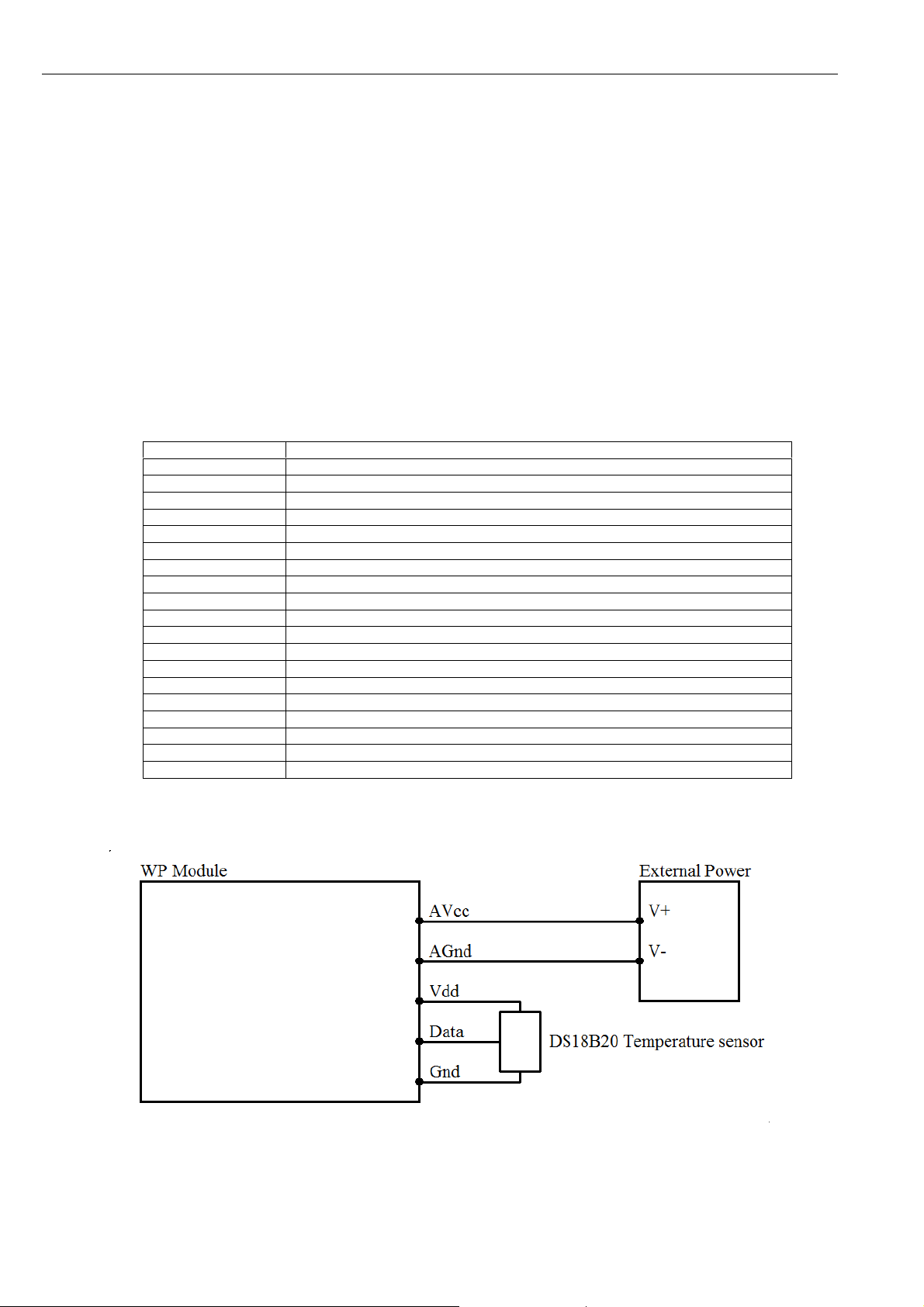
4、Temperature input application diagram
Page 3
WP3066ADAM User’s Manual V1.42A
5、Communication description
5.1、Communication parameter: 9600, None, 8, 1 (default setting)
Parameter
Description
9600
baud rate
None
check bit
8
data bit
1
stop bit
5.2、Command for temperature input data reading
Send: 01 03 00 00 00 08 44 0C (example/hex)
data
byte
data description
remark
01
1
module address
address range:01-FE
03
1
function code
03-read holding register
0000
2
register address (4X type)
0000-starting register address
0008
2
register number
0008-read 8 registers
440C
2
CRC check code
CRC check code for all data
Receive: 01 03 10 00 F2 FF FF FF FF FF FF FF FF FF FF FF FF FF FF 68 9C (example/hex)
data
byte
data description
remark
01
1
module address
address range:01-FE
03
1
function code
03-read holding register
10
1
byte of data
10-read 16 bytes
00F2
FFFF
FFFF
FFFF
FFFF
FFFF
FFFF
FFFF
16
read data
00F2–temperature input channel 1 data
FFFF–temperature input channel 2 data
FFFF–temperature input channel 3 data
FFFF–temperature input channel 4 data
FFFF–temperature input channel 5 data
FFFF–temperature input channel 6 data
FFFF–temperature input channel 7 data
FFFF–temperature input channel 8 data
689C
2
CRC check code
CRC check code for all data
This command reads module’s temperature input data.
The data is hexadecimal data which needs to be converted to decimal data. Put it in the formula and calculate.
A、If data = 65535, the temperature sensor is not connected
B、If data > 10000 and data < 65535, the temperature is below 0℃
TEMP = -(DATA-10000)/10
C、if data < 10000, the temperature is over 0℃
TEMP = DATA/10
5.3、Command for module address setting
Send:00 06 00 64 00 01 08 04 (example/hex)
date
byte
data description
remark
00
1
module address
00-broadcast address
06
1
function code
06-write single holding register
0064
2
register address (4X type)
0064-module address register
0001
2
write data
0001-new module address, range:0001-00FE
0804
2
CRC check code
CRC check code for all data
Receive:00 06 00 64 00 01 08 04 (example/hex)
This command sets module address (slave address) as “01” (default setting). This setting could be saved when power off.
This is a broadcast command. It needs to ensure that only one module is connected to the master.
When module receives correct command, it will send response back to the master.
Page 4

WP3066ADAM User’s Manual V1.42A
5.4、Command for communication parameter setting
Send:01 06 00 65 00 02 18 14 (example/hex)
data
byte
data description
remark
01
1
module address
address range:01-FE
06
1
function code
06-write single holding register
0065
2
register address (4X type)
0065-communication parameter register
0002
2
write data
0001- 4800, None, 8, 1
0002- 9600, None, 8, 1
0003- 19200, None, 8, 1
0004- 38400, None, 8, 1
0005- 4800, Even, 8, 1
0006- 9600, Even, 8, 1
0007- 19200, Even, 8, 1
0008- 38400, Even, 8, 1
1814
2
CRC check code
CRC check code for all data
Receive:01 06 00 65 00 02 18 14 (example/hex)
This command sets communication parameter as “9600, None, 8, 1” (default setting). This setting could be saved when
power off.
When module receives correct command, it will send response back to the master.
6、POWER/DATA LED description
⚫ When module powered on, LED is green.
⚫ When module is under communication, LED is twinkling.
⚫ When module receives correct command, LED is green.
⚫ When module receives incorrect command or other module’s command, LED is red.
7、PC debugging description
We provide a debugging software for function testing and parameter setting. Please follow the steps below:
⚫ Connect computer to module with RS485 converter.
⚫ Connect DC12V or DC24V power to module and power on. To avoid any unnecessary damage, please make sure the
power positive and negative terminals are correctly connected before power on.
⚫ Open the software and select the model of module, you will see the window of function testing or parameter setting.
⚫ Set communication parameter and open the serial port.
⚫ Select corresponding setting and click “Read” or “Write” button.
Page 5
WP3066ADAM User’s Manual V1.42A
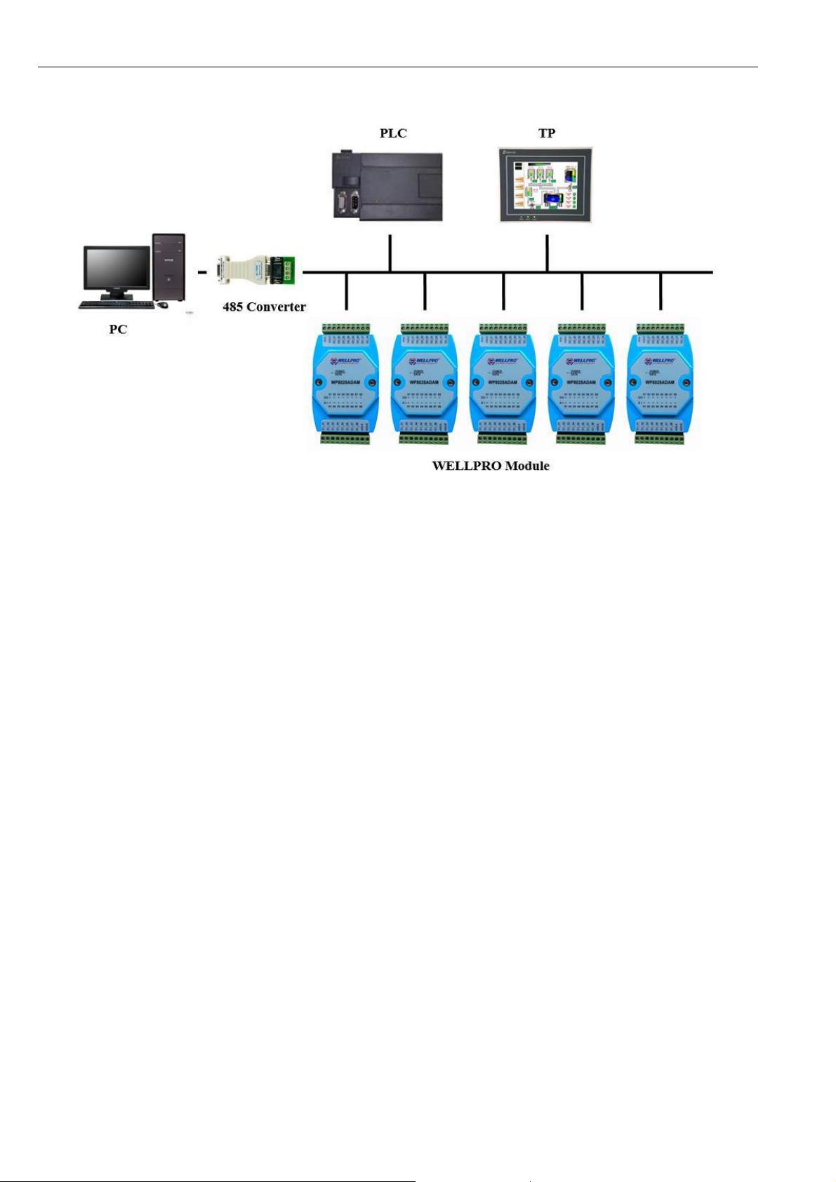
8、RS485 network diagram
 Loading...