

Page 1
Series
6900
Installation, Operation & Maintenance Instructions
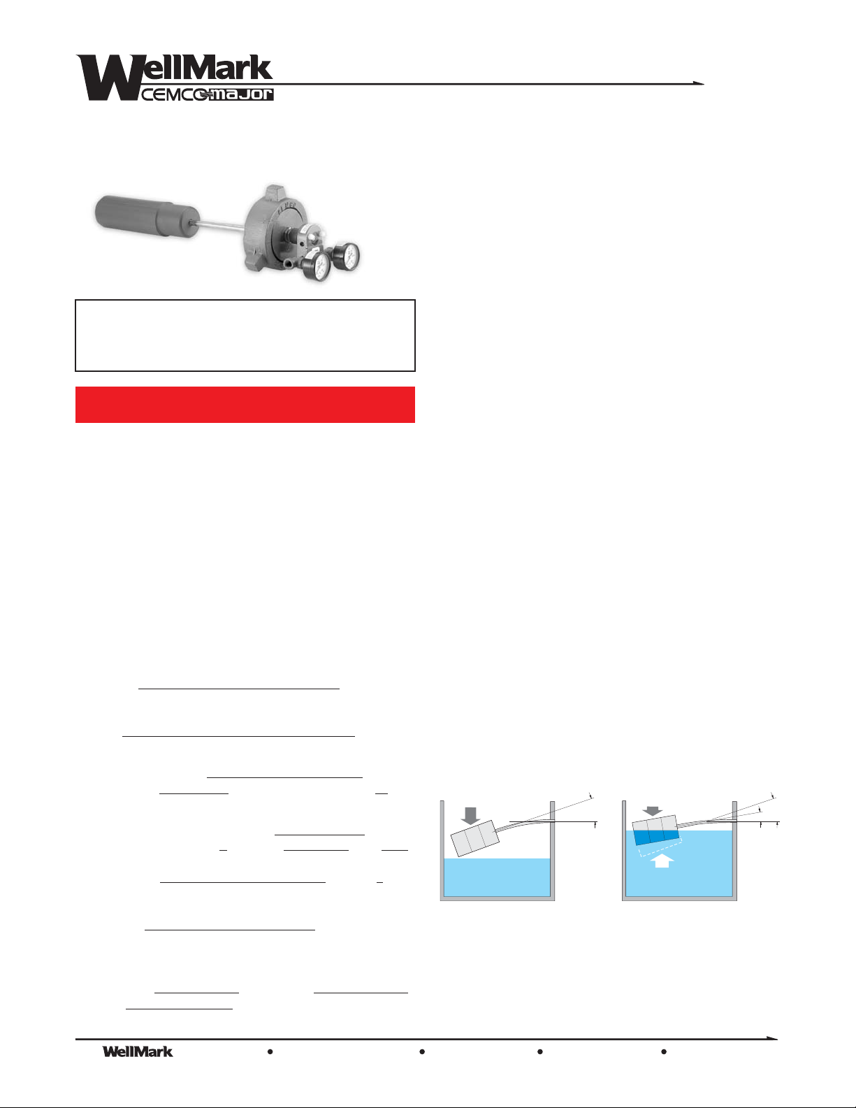
for Series 6900 Cantilever Liquid Level Control
Note: This document is to be used in conjunction
with WellMark Catalog Document, Section No.
3.5, “Series 6900 CantileverLiquid Level Control”.
WARNING!
Over-pressure of this control or installation of the
control in applications which may see pressure
levels beyond those for which the control is
designed may result in leakage and/or catastrophic
failure. This failure could result in leaking gas, or
produced liquid, damage to surrounding equipment
and/or environment, personal injuryor death.
Suitable pressure-relieving devices, as
recommended by appropriate codes or standards,
should be installed in your system to assure that
maximum rated pressures arenot exceeded.
Specifications
Connections
Process 2” MNPT Std.
3”, 4”, 5”, 6” Flanges, Yale and HammerUnion
Configurations also available
Pilot 1/4” FNPT
Output
Throttle (Proportional) 3-15 psig
Snap-Acting 0 to Full Supply (Pilot rated to psi)
General
Maximum Working Pressure (CWP) 1500 psi
Pilot Operating Pressure Normal: 20 -30 psi
Overpressure Protection: Gauges are the limiting factor.
Temp. Limits -40°F to + 00°F
(Higher temperatures available - Consult factory)
Materials
Displacer PVC (165°F max.)
Sight Glass Polycarbonate
Seals Buna-N standard (others available)
psi minimum Max.
Delrin (200°F max.)
Phenolic Screw-on (275°F max.)
Phenolic Slip-on (400°F max.)
(Pyrex® available)
75
2
Application
The Series 6900CantileverLevelControl is designed for useinliquid
level and interface liquid control applications. They are commonly
used in oil and gas processing, manufacturing plants, hazardous
waste disposal, food processing, water treatment, petrochemical
facilities or wherever fluid levels need to be controlled. The unit is
available in eitherSnap-ActingorThrottling configuration, controlling
pneumatic pressure for various control devices. The standard
displacer is 2” x 10” Delrin and is mounted in a horizontal
configuration. Displacers of othermaterials and dimensions,as well
as VerticalDisplacersareoptionallyavailable.
PrincipleofOperation
This liquid level control operates based on two physical laws:
w
“A solid, heavier than a fluid [such as a displacer] will descend to
the bottom of the fluid, and the solid will, when weighed in the fluid,
be lighter than its true weight by the weight of the fluid displaced.”
Archimedes’Principle
A Cantilever beam (sensing rod) projecting outward, anchored at
w
one end,will flex in proportionot the weightapplied, or removed, at
the free end.
Therefore, following Archimedes Principle,a body (displacer orfloat)
immersed in a fluid experiences a bouyant, or lift force equal to the
weight of the displaced fluid. This static lift force acts vertically
through the center of gravity of the displaced volume (Figure 1).
Weight
(Deflection exaggerated for clarification)
Applying the above fundamentals to this liquid level control, we can
sense and regulate levels of most gas-to-fluid interface applications
as well as many fluid- to-fluid interfaces.
H
Figure 1
Weight
1
H
2
Bouyant
Force
Fluid level
rises
-
H
1
The Company, L.L.C. Oklahoma City, Oklahoma Tel: (405) 672-6660 Fax: (405) 672-6661
© The WellMark Company • Litho USA • All registered trademarks are the property of their respective owners. • IOM-6900 090923
wellmarkco.com
1
Page 2
Series
6900
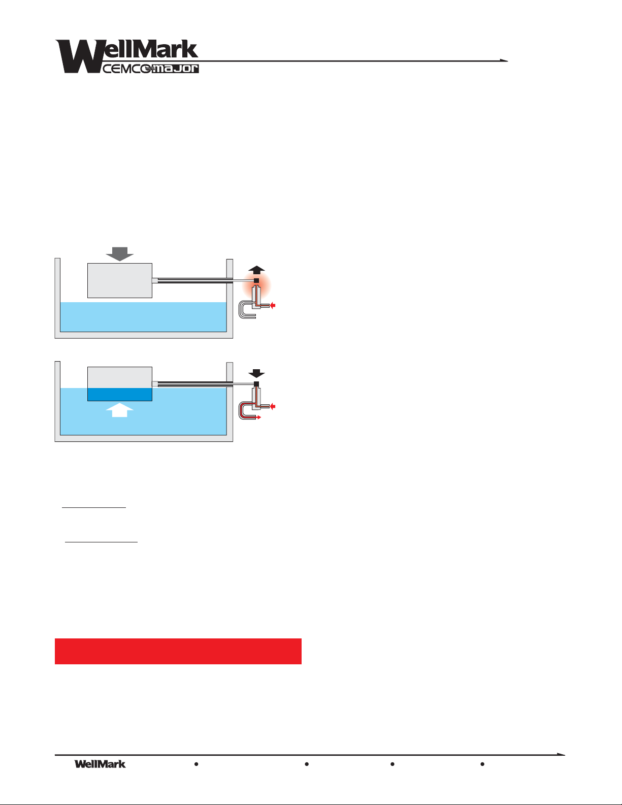
By attaching a Displacer to the free end of the Sensing Rod, vertical
movement is achieved. The rising and lowering ofthe fluid gives the
static lift force - either up or down - which is transferred along the rod
to an Actuator Pad (seat) extending out past the anchored end (See
Figure 2). As theActuatorPadmoves to the Nozzle,supply pressure
is diverted tooutput, opening a diaphragm-operatedmotor valve. As
fluid isdrained away throughthe motor valve and fluid level declines,
the Actuator Pad moves up and away from the Nozzle and supply
pressure is exhausted from the valve, thereby allowing it to close.
This cycle then repeats as necessary.
WEIGHT
Nozzle
Seat
Supply
To Valve
Nozzle
Seat
If supply gas is flammable or noxious, this product
must be located in a well ventilated, non-hazardous
area or sealed andvented to a non-hazardous area.
Insure thatthreaded connections on both theSeries 6900 Cantilever
Level Control and the vessel are clean, free of debris and
undamaged prior to installing. Visually inspect the unit, observing
that the Nozzle Seat and rod-end are centered in the Sensing Rod
connector. If not, the unit has been distorted and should bereturned
to center before placing the control in service (See “Centering
Sensing Rod” in the following section).Maintenance
Install the control into appropriately-sized mating female threaded
connections or flanges. For threaded connections utilize a suitable
thread sealant to assure leak-tight makeup and to avoid thread
galling. For flanged connections, utilizeproper gaskets or seal rings
as required for the specific flange configuration. After installation in
the vessel, check for mechanical clearance of Displacer, assuring
free movement by flicking the actuator pad and observing that
Displacer travel is unobstructed.
Connect instrument supply line to supply port marked “ ” on side of
the unit. Connect control valve signal line to “ ” port on the
opposite side. Use a suitable thread sealant to assure leak-tight
make up and to avoid thread galling. Do not over-tighten.
IN
OUT
Supply
BOUYANT FORCE
Figure 2
Modes:
throttling mode
In , this control will continually throttle the valve to
maintain the fluid level at a desired set point.
snap-acting mode
In , a Shuttle Pilot is attached to the throttling
head, converting the throttling output pressure to pilot signal
pressure, tripping the shuttle pilot to either full supply pressure,
opening the valve quickly, or to zero supply pressure, allowing the
valve to close.
To Valve
Installation
WARNING!
Prior to installation of the 6900 Cantilever Level
Control system must be isolated from pressure.
Failure to do so may result in personal injury,
environmental spill concerns and/or damage to
equipment.
NOTE: 20-30 psi is recommendedfor proper operation. Supply
gas should be clean (filtered) and dry to assure longer
maintenance-free operation.
Start-Up
Remove the clear Cover Plate and visually check to determine that
the Sensing Rod/Nozzle Seat is properly centered in the Cantilever
Tube. If not, the Cantilever Rod assembly has become misaligned
and must be adjusted before placing the control in service (See
“Centering Sensing Rod” in the following section).
Assure that the vessel liquid levels are below the Displacer, and that
proper system shut-off valves are open or closed as required.
Energize the control by opening the supply gas to the pilot head (2030 psi recommended). Supply gasshouldflowfreelyfromtheNozzle
orifice.
Square the Nozzle Seat and Nozzle orifice. Manually hold the
Nozzle Seat against the Nozzle. Observe the Outlet Pressure
Gauge (left-hand gauge). The outlet pressure should equal the inlet
pressure within 1 psi. If not, inspect the supply system piping for
leaks or malfunctions. Release theNozzle Seat, again allowing free
flow of supply pressure from the orifice. Outlet Pressure Gauge
should again read zero. Reinstall the clear Cover Plate.
Maintenance
The Company, L.L.C. Oklahoma City, Oklahoma Tel: (405) 672-6660 Fax: (405) 672-6661
2
© The WellMark Company • Litho USA • All registered trademarks are the property of their respective owners. • IOM-6900 090923
wellmarkco.com
Page 3
Series
6900
Adjust the Adjusting Screw/Nozzle upward toward the Nozzle Seat,
by loosening Jam Nut and turning Adjustment Screw clockwise
(when looking at the bottom of the unit) until Output Pressure Gauge
starts to indicate a reading (1-3 psi).
Open the vessel inlet and observe the rising liquid level. Once the
liquid reaches the Displacer fine adjustment of the control can be
made within the diameter range of the Displacer by adjusting the
Adjusting Screw up or down to actuate the diaphragm-operated
motor valve. Once thedesiredadjustmentsarecomplete,tighten the
Jam Nut, being very careful not to inadvertently disturb theAdjusting
Screw setting.
To INCREASE Liquid Level
clockwise (moves Nozzle orifice away from actuator pad).
To DECREASE Liquid Level
(moves Nozzle orifice toward actuator pad).
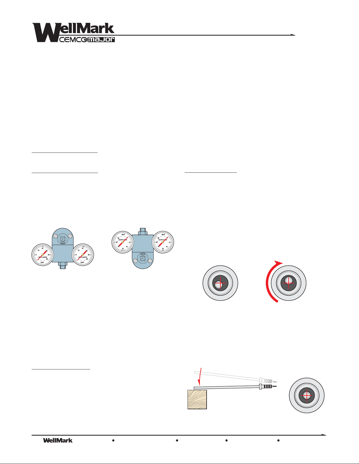
Normal pilot installation is (rise in liquid level resulting
from an increase of output). For (rise in liquid level
resulting in a decrease of output), simply loosen 3/4-16 Jam Nut
behind Pilot Head, androtatePilotHead180° and re-tighten Jam Nut
(See Figure 3).
- Turn Adjusting Screw counter-
- Turn Adjusting Screw clockwise
direct-acting
indirect-acting
the Pilot Housing.
Remove O-Rings from Adjusting Screw. Clean Adjusting
Screw/Nozzle with solvent. Inspect for debris in orifices on side and
end of Nozzle, removing as necessary with thin gage wire. Care
should be exercised not to deform the orifice openings.
Inspect O-Rings for wear and replace if necessary. Lubricate ORings with a light coating of general-purpose grease and reinstall on
the Nozzle. Take care that no grease clogs the orifices.
Gently re-insert the Adjusting Screw/Nozzle with O-Rings back into
the Pilot Housing, taking care not to damage the O-Rings in the
process. Readjust the Nozzle as directed on Page 2 under “Start
Up”. Once proper adjustment is made re-tighten the Jam Nut.
Centering Sensing Rod
Occasionally, the Sensing Rod/Nozzle Seat will become misaligned
in the Sensing Rod Housing and must be re-alinged prior to
installation and use. This is a relatively easy procedure.
Once the unit is removed from service, remove the entire Rod
Assembly from the Pilot Head, detaching the Displacer as well.
Remove the Nozzle Seat by loosening the Hex Nut and pulling the
Nozzle Seat off the Sensing Rod. Peer into the end of the Rod
Assembly and note in which direction the Sensing Rod is off center.
Direct-Acting Indirect-Acting
Figure 3
Maintenance
The Series 6900 Cantilever Liquid Level Control requires very little
maintenance. As with any instrumentation, the most important
factors for long life and consistent operation is that supply pressure
be clean and dry.
From time to time the entire pilot head may come loose on the
Cantilever Rod. Check to assure that this connection is sound and
that the jam nut is properly tightened.
Clearing a Clogged Orifice
The flow of gas in the supply line will draw any foreign material or
particles as the gas moves to and through the control and valve.
Occasionally, this may result in a particle of sand, weld slag, etc.
becoming lodged in an orifice in theAdjustingScreworNozzle.
Shut off supply pressure to the control. Loosen the Jam Nut on the
bottom of the unit and unscrew the Adjusting Screw/Nozzle from the
Pilot Housing. Pull the Adjusting Screw/Nozzle completely free of
Rotate the Rod Assembly such that the Sensing Rod offset is now in
the uppermost or 12-o’clock position (See Figure 4).
12 o’clock
Figure 4
Grasp the Rod Assembly by this end and lightly tap the opposite end
(the Displacer end) on a bench or block of wood. The Sensing Rod
will begin to move back into the center of the Sensing Rod Housing.
Continue with light taps until the Sensing Rod is properly centered
(Figure 5).
Lightly tap
Figure 5
Correct
Alignment
The Company, L.L.C. Oklahoma City, Oklahoma Tel: (405) 672-6660 Fax: (405) 672-6661
© The WellMark Company • Litho USA • All registered trademarks are the property of their respective owners. • IOM-6900 090923
wellmarkco.com
3
Page 4
Series
6900
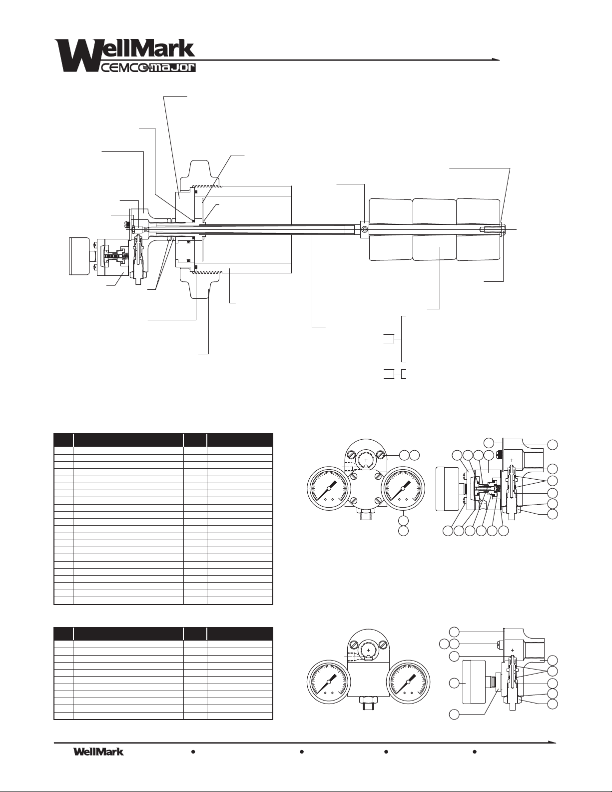
O-RING
05000-0447
HEAD ASSEMBLY
THROTTLING 06500-1307
SNAP ACTING 06500-1315
THROTTLING MIZER¨ 06500-6947
SNAP ACTING MIZER¨ 06500-6955
NOZZLE SEAT
05010-1781
HEX NUT
05000-1510
SNAP ACTING
HEAD
WELD NECK O-RING
3" 05000-0405
4" 05000-0561
5" STD. 05000-0579
5" ACME 05000-5537
JAM NUT
05010-2359
FLANGE
3" BLIND 05011-0337
3" SIGHT GLASS 05011-0667
4" BLIND 05010-5766
4" SIGHT GLASS 06500-204
5" SIGHT GLASS 06500-2917
5" ACME SIGHT GLASS 06500-5076
TRU-ARC RING
(SIGHT GLASS ONLY)
06000-0692
HAMMER UNION
3" BLIND FLG. 06500-0663
3" SIGHT GLASS 06500-0671
4" STD. THREAD 05012-6705
4" ACME THREAD 05012-3702
5" STD. THREAD 05012-9439
5" ACME THREAD 05012-9496
2” MNPT PLUG
05010-5709
0
REFLECTOR
(SIGHT GLASS MODELS ONLY)
3" 05011-0741
4"& 5" 10052
WELD NECK
3" X 5" LG. 05011-2200
3" X 8" LG. 05010-2961
4" X 5" STD. 05011-5468
4" X 8" STD. 05010-1799
4" X 5" ACME 05013-0216
4" X 8" ACME 05012-3694
5" X 8" STD. 05010-4686
5" X 6" ACME 05012-9470
5" X 8" ACME 05013-0232
FLANGE
2"-150RF 05013-0869
2"-300RF 05012-9454
3"-150RF 05011-5922
3"-300RF 05011-5948
3"-600RF 05011-5955
4"-150RF 05010-6889
4"-300RF 05010-6897
4"-600RF 05010-6905
COLLAR
(LONG ROD ONLY)
10059
SENSING ROD ASSEMBLY
SHORT 06500-0630
MEDIUM 06500-0036
LONG 06500-0085
OFFSET 06500-0002
WASHER
(LONG & OFFSET ROD ONLY)
06000-1054
HEX SCREW
(LONG & OFFSET ROD ONLY)
05000-1767
DISPLACER
2" X 10" DELRIN¨ 05011-1582
2" X 12" DELRIN¨ 05011-1590
2" X 10" PHENOLIC 06500-2545
2" X 12" PHENOLIC 06500-2537
2 1/2" X 8" DELRIN¨ 05011-0311
2 1/2" X 7" DELRIN¨ 05011-0584
2 3/4" X 10" PVC 30055
2 1/2" X 8" DELRIN¨ 05011-0352
3 1/4" X 2 3/4" PHENOLIC 05010-2342 (3 Req’d.)
(illustrated)
Parts List for Snap-Acting Pilot Head
Item Qty. Part NumberDescription
PILOT HOUSING, ALUM. ALLOY383
1
STREET-L, MALLEABLE
2
PRESSURE GAUGE
3
ADJUSTING SCREW, 303 SS
4
NOZZLE, 303 SS
5
O-RING, NITRILE
6
JAM NUT, 18-8 SS
7
O-RING, NITRILE
8
COVER PLATE, POLYCARBONATE
9
COVER SCREW, NYLON
10
O-RING, NITRILE
11
BOOSTER BODY,ALUMINUM
12
COVER, ALUMINUM
13
LOWER SEAT, ALUMINUM
14
UPPER SEAT, ALUMINUM
15
CONNECTOR, ALUMINUM
16
SCREW, PLATED STEEL
17
SPRING, ASTM A-313
18
DIAPHRAGM, FAIRPRENE
19
GASKET, FAIRPRENE
20
FILSTER HEAD SCREW, STEEL
21
DAMPENER, SS
22
1
2
2
1
1
2
1
1
1
2
2
1
1
1
1
1
1
1
1
1
4
1
Parts List for Throttling Pilot Head
Item Qty. Part NumberDescription
PILOT HOUSING, ALUM. ALLOY383
1
STREET-T, MALLEABLE
2
PRESSURE GAUGE
3
ADJUSTING SCREW, 303 SS
4
NOZZLE, 303 SS
5
O-RING, NITRILE
6
JAM NUT, 18-8 SS
7
O-RING, NITRILE
8
COVER PLATE, POLYCARBONATE
9
COVER SCREW, NYLON
10
O-RING, NITRILE
11
1
2
2
1
1
2
1
1
1
2
2
05010-3472
06000-0684
06000-0700
05010-1674
05010-1682
05000-0033
05010-2334
05000-0074
05010-3720
05010-3761
05000-0009
05010-3456
05010-3464
05010-3423
05010-3431
05010-3449
05000-2591
05010-3704
05010-3712
05010-3696
06000-1601
05010-3829
05010-1617
06000-0676
06000-0700
05010-1674
05010-1682
05000-0033
05010-2334
05000-0074
05010-3720
05010-3761
05000-0009
15
10
WELLMARK
0
psi
15
10
WELLMARK
0
psi
9
10 11
15
20
255
30
10
WELLMARK
0
psi
20
255
30
13 15 16 12
2
3
21 19 201817 14
1
5
6
4
8
7
9
10 11
5
15
20
255
30
10
WELLMARK
0
psi
20
255
30
3
1
6
4
8
7
2
The Company, L.L.C. Oklahoma City, Oklahoma Tel: (405) 672-6660 Fax: (405) 672-6661
4
© The WellMark Company • Litho USA • All registered trademarks are the property of their respective owners. • IOM-6900 090923
wellmarkco.com
 Loading...