

Page 1
Installation, Operation & Maintenance Instructions
Note: This document is to be used in conjunction
with WellMark Catalog Document, Section No.
5.2, “Series 2001PR Top Gun High Pressure
Regulator”, pages 3 through 5.
WARNING!
Series
2001PR
for Series 2001PR “Top Gun” Regulator
Make sure that line pressure has been eliminated prior to the
installation of any regulator. Prior to installation the line should be
inspected to ensure that there is no debris that might damage the
regulator. Install regulator with properly sized threaded connections
and utilizing thread sealant.
The regulator should be installed with the flow arrow on the side of
the body in the correct orientation to flow - i.e. higher pressure
upstream, lower regulated pressure downstream.
most regulators, the Series 2001PR regulator has an outlet
pressure ratingthat isless thanthe inletpressure rating. Overpressure protection must be provided to avoid over-pressure
condition if the actual inlet pressure can exceed the outlet
pressure rating. Refer to Table 1 and 2 for maximum inlet
pressures, pressure drops andoutletpressure ranges.
The regulator maybeinstalled in anyorientationas long astheflow is
in proper agreement with the flow arrow on the side of the body.
However, the regulator should be positioned such that the screened
Breather (24) will notcollectdebris or moisture.
As is true with
Over-pressure of this regulator or installation of the
regulator in applications which may see pressure
levels beyond those for which the regulator is
designed may result in leakage and/or catastrophic
failure. This failure could result in leaking gas,
damage to surrounding equipment, personal injury
or death. To prevent such damage/injury the
regulator should be installed in a safe location and
should be chosen based upon the user’s specific
application.
It is highly recommended that suitable pressurerelieving devices, as recommended by appropriate
codes or standards, be installed in your system to
assure that maximum rated pressures are not
exceeded.
Installation
The Series 2001PR Top Gun Regulator should be chosen based
upon the maximum inlet pressures, pressure drops and outlet
pressures as described inTable 1 and 2. Flow capacities are listed in
Table 3. The operating temperature range is -20°F to 150°F. When
choosing and installing a regulator one must ensure that the
conditions do not exceed these parameters. Furthermore, large
differentials in pressure across the regulator may result in the
formation of ice in the orifice area. The resulting decrease in orifice
area may affect the regulators ability to flow in sufficient volume for
downstream demand. Therefore, large pressure drop applications
may require the useofmore than one regulator.
VentLine Option
The Series 2001PR Top Gun Regulator includes a vent or Breather
(24) in the Spring Housing (3). If there is concern about build-up of
gas in a confined location, the Breather may be removed to allow
installation of a remote vent line. With the Breather removed, a vent
line may be installed into the1/4” NPT port. This vent line should be
as large a diameter aspossible and shouldutilize minimal bends and
elbows. Furthermore, the ventlineopening should be protectedfrom
weather or debris andshouldbe checked regularly forblockage.
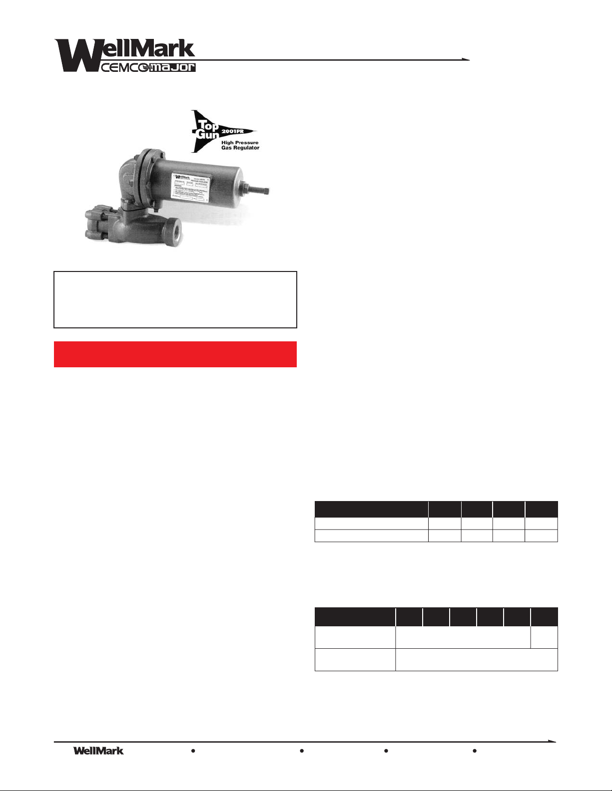
Table 1: Maximum Pressures and Pressure Drops
Port Diameter 1/8” 1/4” 3/8” 1/2”
Max. Allowable Inlet Pressure, psig 1500 1500 1000 750
Max. Allowable Pressure Drop, psid 1500 1000 500 250
The sum of the outlet pressure setting and the maximum allowable pressure drop
1
determines the maximum allowable inlet pressure for a given installation. For example,
with a 3/8” seat ring orifice (maximum pressure drop of 500 psi) and a 275 psig outlet
pressure setting,themaximum inlet pressure is 775psig (500 psi + 275psi+ 775 psi).
1
Table 2: Outlet Pressure Ranges
Outlet Pressure Range psig
Max. Outlet Pressure over
Pressure setting , psig
Max. Emergency Outlet
(Casing) Pressure, psig
Internal parts of the regulator may be damaged if theoutlet pressure exceeds the pressure
1
setting beyondtheamounts shown.
This applies to outlet pressure settings below 350 psig only. For pressure settings above
2
350 psig, outlet pressure is limited to 550 psig, the maximum emergency outlet (casing)
pressure.
1
27-50 46-95 90-150
200 200
150-200 200-275 275-500
550
2
The Company, L.L.C. Oklahoma City, Oklahoma Tel: (405) 672-6660 Fax: (405) 672-6661
© The WellMark Company • Litho USA • All registered trademarks are the property of their respective owners. • IOM-2001PR 080604
wellmarkco.com
1
Page 2
Series
2001PR
Startup Operation
WARNING!
Release downstream pressure to prevent a potential
over-pressure of the diaphragm. Failure to do so
may result in property damage and/or personal
injury. Always employ upstream and downstream
pressure gauges to monitor startuppressures.
With the regulator isolated with shutoff valves on both the upstream
and downstream sides, slowly open upstream valve followed by
slowly opening the downstream valve. Check all connections for
leaks and make necessary output adjustments by manipulating the
Adjusting Screw (1) pertheadjustment procedures below.
Adjustment
The range of adjustment for a particular regulator is indicated on the
nameplate. Different ranges can be achieved by substituting a
different Spring (5).
IMPORTANT: If a newspring is installed the nameplate must be
remarked to indicate thenewpressure range.
Refer to Tables 1 & 2 prior to adjustment for pressure and flow
information, assuring that the chosen spring will facilitate the desired
pressure regulation and that the maximum pressure output does not
exceed the downstream systempressurelimits.
Loosen the Jam Nut(2).
ToINCREASEpressure:
TurnAdjustment Screw
ToDECREASEpressure:
TurnAdjustment Screw
Once thedesired pressure is achieved, holdAdjustment Screw while
securing the Jam Nut.
clockwise
counter clockwise
.
.
Shutdown
WARNING!
Downstream pressure must be released to prevent
an over-pressurization of the diaphragm. Failure to
do so may result in property damage and/or
personal injury.
Close the upstream block valve followed by closing the downstream
block valve. Open the nearest vent valve between the regulator and
the downstream block valve.
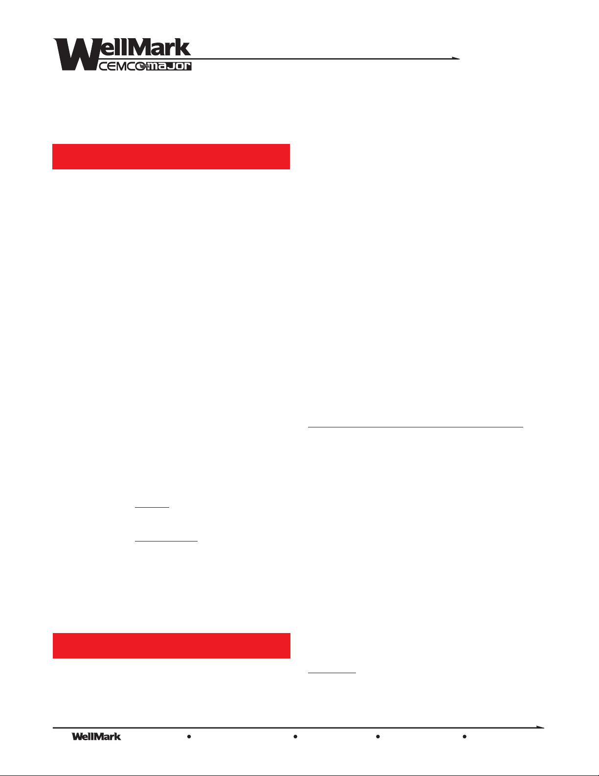
Operation
When the outlet pressure is lower than the set pressure, force
generated by the Spring (5) upon the Spring Guide (7) and
Diaphragm (11) causes the Lever Assembly (14) to hold the valve in
an open condition. As the outlet pressure exceeds the set pressure,
the Diaphragm, acting upon theLower Spring Guidecompresses the
spring allowing the Lever Assembly to close the valve until the outlet
pressure equalizes with thesetpressure.
Maintenance
Routine maintenance should be expected due to normal wear and
tear, damage from external sources or debris. The regulator
components - especially the moving and sealing parts - should be
inspected periodically and replaced as necessary. Frequency of
inspection/replacement depends upon severity of conditions, but
may also be requiredbylocal/state/federal law or industrystandards.
Large pressure drops or large amounts of particulate in the flow will
result in accelerated wear on the (21) and
(20).
Orifice
Replacing the Orifice, LeverAssembly andDiskAssembly
1) Disconnect piping from (18), removing Adapter
and four (17).
2) Remove (20) and (19).
3) Remove vent piping ifitis installed.
4) Remove two (8), which secure the
Adapter Body Diaphragm Adapter
and (3)as a unit.
5) If the is to be replaced, drive out the (15)
and slide the out of the .
When replacing theLeverAssembly, make surethatthe slot engages
the (12). Replace the pin.
6) Remove the (22) from the .
7) Use a 3/4-inch socket to remove and re-install the Valve Disk
and holder.
8) Discard old and replace with new. Reinstall the into the .
9) R
making sure that
Carrier. Finally, tighten the two that secure the
Diaphragm Adapter/Spring Housing Body
IMPORTANT:
away from the (18).
10) Re-install the to the , installing and
tightening the four .
Cap Screws
Orifice Inlet Body Gasket
Cap Screws Diaphragm
(13) to the (23). Remove the
Spring Case
Lever Assembly Pin
Lever Assembly Diaphragm Adapter
Connector Head Assembly
ValveCarrier Body
Inlet Body Gaskets
ValveCarrier Body
e-install the unit,
Diaphragm Adapter/Spring Housing
the Lever Assembly properly engages the Valve
Spring Case
InletAdapter
Inlet Adapter Body
Cap Screws
Valve Disk Assembly
Inlet Adapter
Cap Screws
unit to the
(3) must be oriented such that it points
.
The Company, L.L.C. Oklahoma City, Oklahoma Tel: (405) 672-6660 Fax: (405) 672-6661
2
© The WellMark Company • Litho USA • All registered trademarks are the property of their respective owners. • IOM-2001PR 080604
wellmarkco.com
Page 3
Replacing the Diaphragm
1) Remove spring tension by loosening the (2) and
turning the (1) counter-clockwise until all spring
Adjusting Screw
Jam Nut
compression is relieved.
2) Disconnect vent lineifinstalled.
3) Unscrew two (9) and four (10) with
Hex Nuts
(25).
4) Remove the (3).
5) Remove from the Lever Assembly, as a unit, the
(11), (12), (7) and
Connector Head Assembly Lower Spring Guide
Cap Screw
Cap Screws Cap Screws
Spring Housing
Diaphragm
(6).
Series
6) Unscrew the (6) from the (12) and
disassemble the (11).
7) Install a new , making sure that it is properly
centered. Re-assemble and
Spring Guide Cap Screw
Cap Screw ConnectorHead
Diaphragm
Diaphragm
Connector Head Assembly Lower
, securely tightened withthe .
2001PR
8) Engage Connector HeadinLeverAssembly.
9) Re-install the with and
finger-tight only. Assure proper slack by slightly
compressing the with the (tighten by
turning clockwise). Finally, complete the tightening of all
Screws Nuts
and .
Spring Housing Cap Screws Nuts
Diaphragm
Spring Adjusting Screw
Cap
17
13
14
15
16
18 19 20
25
12
21 22
10 7 6
11
23
24
5
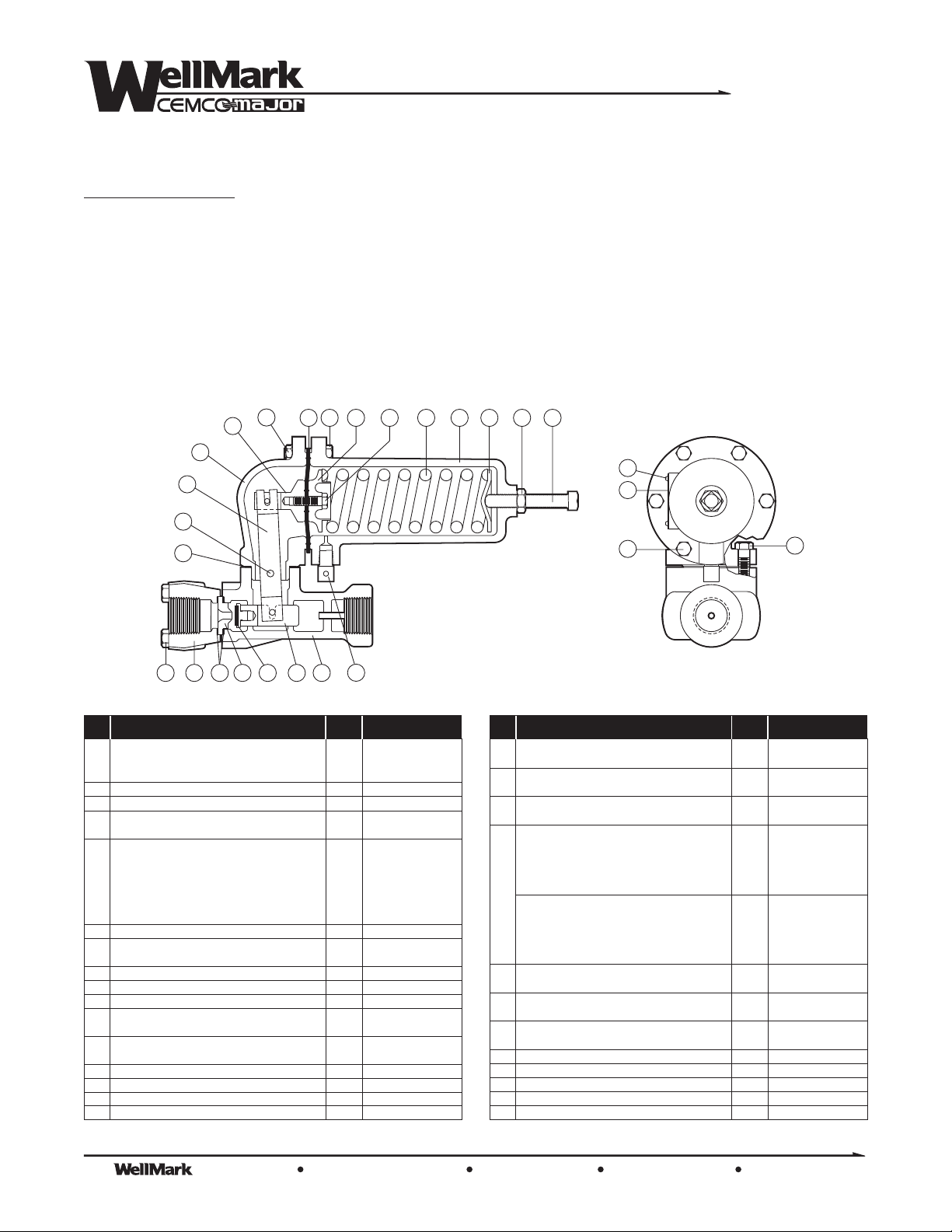
Parts List
Description DescriptionQty. Qty.Part No. Part No.Item Item
Adj. Screw, 27-50 Outlet Pressure 1 11014
1 Adj. Screw, 46-95 Outlet Pressure 1 11013
Adj. Screw, 90-500 Outlet Pressure 1 11097
2 Jam Nut 1 10098
3 Spring Housing 1 40440
Upper Spring Guide, up to 275 psi 1 11001
4
Upper Spring Guide, above 275 psi 1 11032
Spring, 27-50 Outlet Pressure 1 11027
Spring, Outlet Pressure
46-95 1 11028
Spring, 0 Outlet Pressure
5
6 Cap Screw 1 11012
7
8 Cap Screw 2 10090
9 Cap Screw 2 11011
10 Cap Screw 4 11010
11*
12
13 Diaphragm Adapter 1 40443
14 Lever Assembly 1 21023
15 Pin 1 11000
16 Gasket 1 11008
9 -150 1 11002
Spring, 50 Outlet Pressure
1 -200 1 11029
Spring, 2 - 5 Outlet Pressure
00 27 1 11030
Spring, 27 -50 Outlet Pressure
5 0 1 11031
Lower Spring Guide, up to 275 psi 1 40445
Lower Spring Guide, above 275 psi 1 40446
Diaphragm, Neoprene 1 11004
Diaphragm, Viton® 1 11033
Connector Head Assembly, Brass 1 21052
Connector Head Assembly, 316 SS 1 21053
3
4
17
18
19
20
21
22
23
24 Breather 1 05011-1640
25 Hex Nut 4 05000-1726
26 Name Plate 1 21039
27 Drive Screw 4 10075
28 Plug, 1/8” NPT (2” only) 1 06000-0494
1
2
27
26
9
Cap Screw, 1” 4 11009
Cap Screw, 2” 4 11050
Inlet Adapter, 1” Steel 1 40442
Inlet Adapter, 2” Steel 1 40589
Inlet Body Gasket, Copper 2 11005
Inlet Body Gasket, Composition (for NACE) 2 11015
Orifice, Brass 1/8” 1 21042
Orifice, Brass 3/16” 1 21112
Orifice, Brass 1/4” 1 21028
Orifice, Brass 3/8” 1 21040
Orifice, Brass 1/2” 1 21041
Orifice, Stainless Steel 1/8” 1 21043
Orifice, Stainless Steel 3/16” 1 21093
Orifice, Stainless Steel 1/4” 1 21044
Orifice, Stainless Steel 3/8” 1 21045
Orifice, Stainless Steel 1/2” 1 21046
Valve Disk Assembly, Brass/TFE 1 21026
Valve Disk Assembly, 316SS/TFE 1 21047
Valve Carrier, Brass 1 31005
Valve Carrier, 316SS 1 31011
Body, 1” Steel (WCB) 1 40444
Body, 2” Ductile Iron 1 40588
8
The Company, L.L.C. Oklahoma City, Oklahoma Tel: (405) 672-6660 Fax: (405) 672-6661
© The WellMark Company • Litho USA • All registered trademarks are the property of their respective owners. • IOM-2001PR 080604
wellmarkco.com
3
Page 4
Series
2001PR
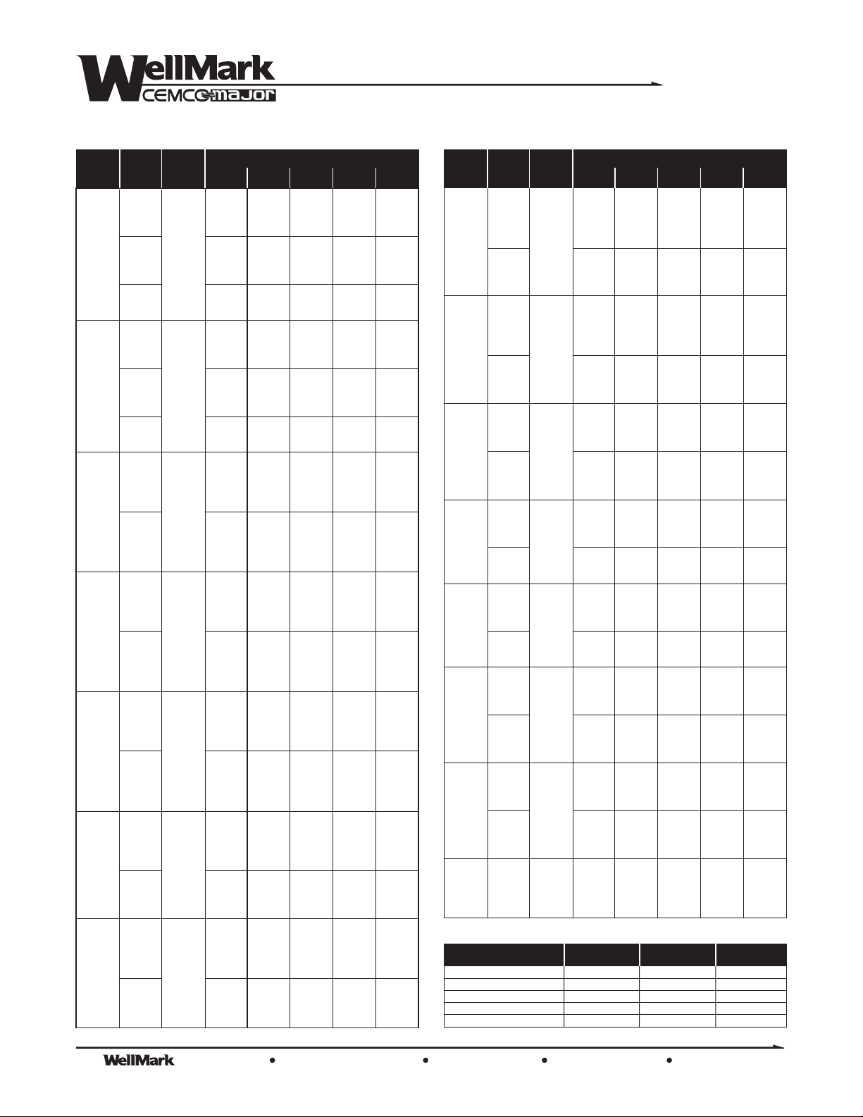
Table 3: High Pressure Regulator Flow Capacities (scfh of 0.6 Specific Gravity Gas; based on 20% Drop)
Outlet
Pressure
Range psig
27-50 300 50 5300 10,500 14,000 20,000 23,000
46-95 300 50 5200 8900 11,000 16,000 20,000
46-95
90-150
90-150
90-150 450 150 7700 17,000 24,000 36,000 —
150-200 450 150 7600 15,000 24,000 36,000 —
Inlet
Pressure
Outlet
Pressure
psig
psig
60 900 2000 3100 5200 8100
75 1300 28500 3800 7200 10,000
100 1700 3500 5700 10,500 13,000
150 2600 5700 8700 13,000 17,000
200 3500 7800 11,000 16,000 19,000
400 6900 13,000 17,000 23,000 —
550 9600 16,000 20,000 26,000 —
600 9800 17,000 21,000 — —
1050 17,000 23,000 27,000 — —
1500 19,000 25,000 — — —
60 800 1500 2400 4300 6400
75 1200 2100 3100 5500 8000
100 1500 3100 4200 7500 10,000
150 2400 4500 6700 11,000 14,000
200 3400 6600 9400 14,000 17,000
400 6800 11,000 15,000 20,000 —
550 9500 13,000 17,000 23,000 —
600 9800 14,000 19,000 — —
1050 14,000 19,000 22,000 — —
1500 18,000 24,000 — — —
100 1700 3200 5000 8000 13,000
125 2200 4300 6700 10,000 15,000
200 3500 7300 10,000 16,000 22,000
250 4400 9400 13,000 19,000 24,000
325 75 5700 11,000 16,000 23,000 27,000
400 7100 14,000 19,000 27,000 —
575 9700 18,000 23,000 30,000 —
600 9900 19,000 25,000 — —
1075 18,000 27,000 32,000 — —
1500 23,000 32,000 — — —
125 2000 3600 5500 9200 13,000
150 2500 4600 6800 11,000 16,000
200 3600 6600 9400 13,000 22,000
250 4400 8500 11,000 18,000 26,000
300 100 5300 9800 14,000 21,000 30,000
350 6100 10,000 16,000 25,000 32,000
400 7000 13,000 18,000 27,000 —
600 9500 18,000 23,000 35,00 —
1100 19,500 28,000 35,000 — —
1500 25,000 35,000 — — —
150 2400 4600 6700 11,000 17,000
200 3500 6800 10,000 15,000 23,000
250 4300 8900 12,000 19,000 29,000
300 5200 10,000 15,000 25,000 34,000
375 125 6600 13,000 18,500 28,000 39,000
400 7300 14,500 19,000 29,000 —
500 7900 15,000 25,000 36,000 —
625 10,000 22,000 29,000 41,000 —
1125 18,000 33,000 42,000 — —
1500 26,000 43,000 — — —
200 2400 6800 10,000 16,000 26,000
250 4400 8800 13,000 20,000 32,000
300 5300 10,000 15,000 24,000 35,000
400 7100 14,000 22,000 34,000 42,000
650 9000 24,000 33,000 49,000 —
800 13,000 29,000 38,000 — —
1150 20,000 38,000 49,000 — —
1500 26,000 47,000 — — —
200 3400 6200 9300 16,000 24,000
250 4300 8800 12,000 20,000 27,000
300 5300 10,000 15,000 24,000 30,000
400 7100 14,000 21,000 32,000 38,000
650 9000 21,000 33,000 48,000 —
800 13,000 27,000 37,000 — —
1150 19,500 34,000 49,000 — —
1500 26,000 44,000 — — —
Seat Ring Orifice Diameter (Inches) Seat Ring Orifice Diameter (Inches)
1/4 1/41/2 1/23/8 3/83/16 3/161/8 1/8
Outlet
Pressure
Range psig
150-200 700 200 11,000 25,000 40,000 61,000 —
200-275 700 200 11,000 25,000 35,000 55,000 —
200-275
200-275 775 275 11,000 28,000 51,000 95,000 —
275-500 775 275 11,000 24,000 32,000 55,000 —
275-500
275-500
250-500 900 500 15,000 34,000 52,000 92,000 —
Inlet
Pressure
Outlet
Pressure
psig
psig
250 4200 8300 12,000 20,000 30,000
300 5200 10,000 16,000 25,000 35,000
450 7800 16,000 26,000 43,000 50,000
600 9500 22,000 34,000 55,000 —
800 13,000 30,000 43,000 — —
1000 16,000 37,000 50,000 — —
1200 20,000 41,000 59,000 — —
1500 26,000 53,000 — — —
250 4200 8200 11,000 20,000 29,000
300 5200 10,000 14,500 25,000 35,000
450 7700 16,000 24,000 40,000 50,000
600 9500 22,000 31,000 51,000 —
800 13,000 29,000 42,000 — —
1000 16,000 36,000 50,000 — —
1200 19,000 41,000 55,000 — —
1500 26,000 51,000 — — —
300 4900 9000 15,000 28,000 42,000
400 7000 14,000 23,000 40,000 56,000
500 8500 18,000 29,000 51,000 65,000
600
750 12,500 28,000 44,000 69,000 —
1000 16,000 39,000 58,000 — —
1250 21,000 49,000 69,000 — —
1500 26,000 59,000 — — —
300 4700 9000 15,000 28,000 39,000
400 6900 14,000 25,000 40,000 54,000
525 8600 18,000 35,000 68,000 94,000
1000 16,000 39,000 67,000 — —
1275 21,000 50,000 87,000 — —
1500 26,000 60,000 — — —
300 4500 7500 10,000 20,000 31,000
400 6600 12,000 16,000 31,000 43,000
525 8600 16,000 21,000 39,000 56,000
1000 17,000 32,000 43,000 — —
1275 21,000 40,000 53,000 — —
1500 26,000 46,000 — — —
400 6600 11,000 16,000 31,000 42,000
550 9700 18,000 23,000 44,000 63,000
600 9900 19,000 26,000 48,000 —
700
800 13,000 26,000 35,000 61,000 —
900 15,000 29,000 39,000 — —
1300 22,000 43,000 58,000 — —
1500 26,000 49,000 — — —
500 8300 16,000 24,000 44,000 62,000
650 10,000 24,000 33,000 61,000 86,000
800 13,000 30,000 41,000 76,000 —
900
1000 17,000 38,000 54,000 — —
1200 20,000 46,000 63,000 — —
1400 24,000 55,000 76,000 — —
1500 26,000 60,000 — — —
550 8700 16,000 26,000 50,000 77,000
750 12,000 28,000 40,000 78,000 100,000
1000 17,000 39,000 60,000 100,000 —
1500 26,000 59,000 72,000 — —
9500 22,000 34,000 59,000 —
250
11,000 23,000 30,000 54,000 —
300
15,000 34,000 49,000 85,000 —
400
Table 4: Wide-Open Flow Coefficients
Orifice Size C
1/8 inch 13.9 0.49 28.4
3/16 inch 31.3 1.11 28.2
1/4 inch 55.1 2.03 27.2
3/8 inch 122.5 4.61 26.6
1/2 inch 216.0 8.18 26.4
g
C
v
C
1
The Company, L.L.C. Oklahoma City, Oklahoma Tel: (405) 672-6660 Fax: (405) 672-6661
4
© The WellMark Company • Litho USA • All registered trademarks are the property of their respective owners. • IOM-2001PR 080604
wellmarkco.com
 Loading...