

Page 1

Series
2001NB
Installation, Operation & Maintenance Instructions
for Series 2001NB Pneumatic Level Control
Note: This document is to be used in conjunction
with WellMark Catalog Document, Section No.
3.1, “Series 2001NB Pneumatic Level Control”,
pages 1 through 3.
WARNING!
Over-pressure of this control or installation of the
control in applications which may see pressure
levels beyond those for which the control is
designed may result in leakage and/or catastrophic
failure. This failure could result in leaking gas, or
produced liquid, damage to surrounding equipment
and/or environment, personal injuryor death.
Suitable pressure-relieving devices, as
recommended by appropriate codes or standards,
should be installed in your system to assure that
maximum rated pressures arenot exceeded.
Specifications
Connections
Process 2” MNPT Std. (Others avaialble)
Pilot 1/4” FNPT
Case Exhaust 1/8” FNPT
Application
The Series 2001NB Pneumatic Level Control is designed for use in
liquid level and interface liquid control applications. The unit is
available in either Snap-Acting or Throttling configurationand is field
reversible for either Left-hand or Right-hand orientation.
Furthermore, the unit can be set up for Direct or Reversing Acting
operation. This standard displacer is 1-7/8” x 12” PVC in horizontal
configuration. Displacers of other materials and dimensions, as well
as VerticalDisplacersareoptionallyavailable.
VesselInstallation
WARNING!
Prior to installation of the 2001NB Level Control
system must be isolated from pressure. Failure to
do so may result in personal injury, environmental
spill concerns and/or damageto equipment.
Insure that threadedconnections on both the 2001NBand the vessel
are clean, free of debrisandundamagedpriorto installing. Install the
Displacer (32) onto the Displacer Arm (30) by threading it together
(Note: the Displacer Bushing (31) should already be installed in the
Displacer). If the unit is configured for Vertical Displacer Assemby,
theAdapter (44) will already beattachedto the DisplacerArm. In this
case, install the Displacer by threading it onto theAdapter. Snug all
threaded connections firmly.
Output
Throttle (Proportional) 3-15 psig or 6-30 psig
Snap-Acting 0 to Full Supply
General
Repeatability 1.0% of Full Scale
Dead Band 5.0% of Input Scale
Linearity 2.0% of Full Scale
Ambient Temp. Effect 1.0% @ -40°F
3.0% @ +180°F
Specific Gravity 0.4 Minimum
Temp. Limits -40°F to +200°F
(Displacer is limiting factor)
Pressure Rating 6000 psi
Pilot Operating Pressure Normal: 20-35 psi
Overpressure Protection: Gauges are the limiting factor.
Maximum Pressure without Gauges 125 psig
The Company, L.L.C. Oklahoma City, Oklahoma Tel: (405) 672-6660 Fax: (405) 672-6661
© The WellMark Company • Litho USA • All registered trademarks are the property of their respective owners. • IOM-2001NB 091007
Install the Control in the vessel. Connect instrument supply line to
SUPPLYport on back. Connect control valve signalline toOUTPUT
port on back. Use asuitable threadsealant to assure leak-tight make
up and to avoid thread galling. Do not overtighten.
CAUTION!
Maximum allowable pressures for this level control are
determined by the rating of the connection. Threaded
connections are rated to 6000 psi @ 100°F. Flanged
connections are subject to the maximum ratings as specified by
ASME B16.5 for specific pressure classes and temperatures.
These pressures should not be exceeded and proper overpressure protection should be employed on vessels where
pressures above maximum may occur. Likewise, displacer
material and configuration should be considered when
determining suitability for a particular application.
wellmarkco.com
1
Page 2
Series
2001NB
Operation
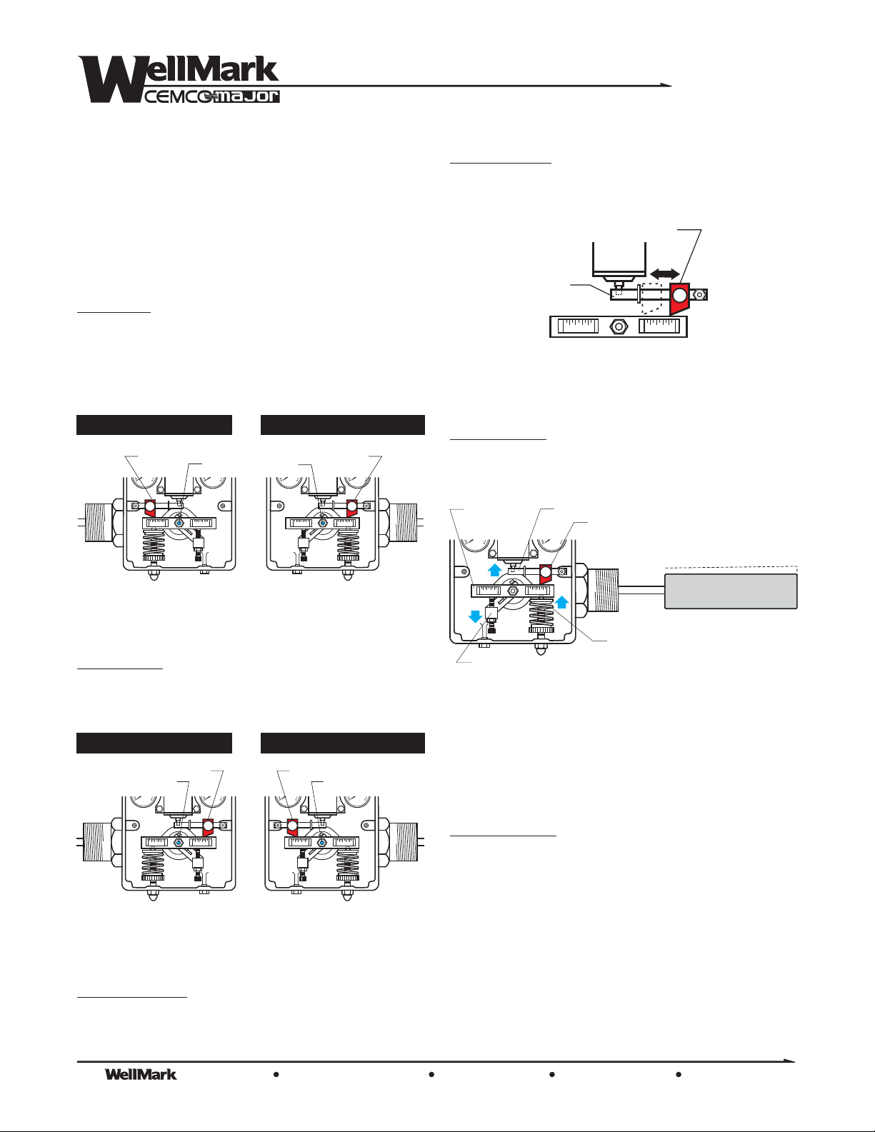
The 2001NB Level Control utilizes a balanced method, whereby a
spring acting on a lever balances the weight of the displacer in the
vessel. As liquid rises in the vessel, force is made available via the
Torque Bar (16) and Fulcrum (26), to the pilot proportional to the
weight of the displaced liquid. As the liquid level rises the amount of
force increases to the pilot.
Direct-Acting
configuration, whereby rising level Pilot
output. When the unit is configured for Direct-Acting operation the
Fulcrum willbe located either left or right of the pivot dependingupon
whether the unit is Left Hand Mount or Right Hand Mount as
illustrated below.
LEFT HAND MOUNT RIGHT HAND MOUNT
FULCRUM
psi psipsi psi
PIVOT PIVOT
increases
FULCRUM
Proportional Band, when referring to a throttling control, is the ratio
of displacer actually used as compared to the overall length of the
displacer. Forinstance, a50% proportional band would utilize6” of a
12”displacer to achieve a 3-to-15 psi output.
FULCRUM
PILOT
FLAPPER
BAR
The Dump Span and Proportional Band are adjusted by moving the
Fulcrum along the Flapper Bar as necessary to achieve the desired
result.
Level Adjustment
- The Displacer’s weight is held in balance by the
Spring (21). Since the Displacer is buoyant, as the level rises the
apparent weight or of the Displacer decreases. As a result of
TORQUE
BAR
PILOT
mass
FLAPPER BAR
FULCRUM
psipsi
Displacer’s apparent weight
decreases as fluid level rises
DIRECT-ACTING
Rising level INCREASES Pilot output
Reverse-Acting
configuration (rising level Pilot output)
decreases
can be accomplished by moving the Fulcrum to the opposite side as
shown below.
LEFT HAND MOUNT RIGHT HAND MOUNT
FULCRUM
PIVOT
psi psi psipsi
REVERSE-ACTING
Rising level DECREASES Pilot output
Span or Dump Span
refers to the differential between ON and OFF.
This is determined by the position of the Fulcrum along the Torque
Bar.
FULCRUM
PIVOT
SPRING
ADJUSTMENT ARM
Rotates down, relieving
pressure on Torque Bar
Differential force increases
as Displacer is unweighted
the rising Displacer the Adjusting Bar rotates, relieving pressure on
the Torque Bar. This results in an increase in differential Spring
force, transmitting that force to the Pilot poppet via the Fulcrum and
Flapper Bar. Increasing tension on the Spring lowers the sensed
level. Conversely, decreasing the spring force raises the sensed
level.
Interface Operation
Some systems require control at theinterface distinction between the
hydrocarbon and water. This is referred to as . It
interface operation
is possible to adjust the Spring to a point at which the hydrocarbon
liquid completely envelopes the displacer without transmitting
enough force to engage the pilot and produce any output.
Water has a higher specific gravity than hydrocarbon and naturally
separates lower, with hydrocarbon liquid rising above it. When
properly adjusted, watercan riseto alevel on the displacer,changing
its apparent weight and causing enough force to engage the pilot,
which will then result in output. The 2001NB unit’s broad range of
control allows liquid interface sensing.
The Company, L.L.C. Oklahoma City, Oklahoma Tel: (405) 672-6660 Fax: (405) 672-6661
2
© The WellMark Company • Litho USA • All registered trademarks are the property of their respective owners. • IOM-2001NB 091007
wellmarkco.com
Page 3
Pilot Operation
Snap-Acting Pilot • No-Bleed On/Off Flow Action
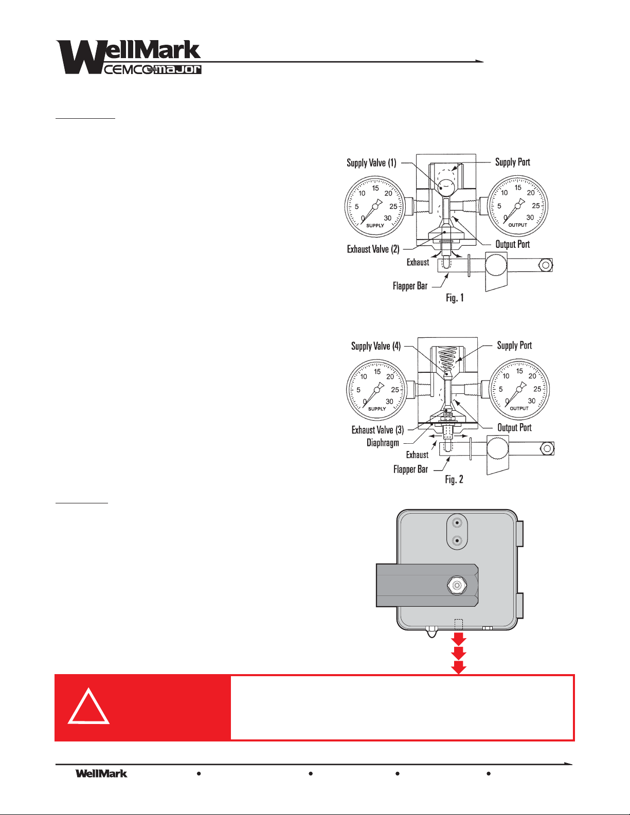
The Snap-Acting Pilot is comprised of two inner valves. Valve (1)
admits system supply gas to output. Valve (2) controls system
exhaust from output. Valve (1), as shown in the closed position (Fig.
1), is held closed by force exerted from supply gas. When upward
Flapper Bar forces transferred to Valve (2) is sufficient enough to
overcome supply force, the ball snaps upward, allowing supply
pressure to communicate to output port, which operates the
diaphragm motor valve (not shown). The spherical end of Valve (2)
closes the exhaust port the instant the ball snaps upward and
remains seated against supply pressure until force on the valve
diminishes. As force is removed from Valve (2),causing it tounseat,
a simultaneous action occurs, causing Valve (1) to seat instantly,
closing the supply port to ouput and opening output to exhaust,
thereby allowing the diaphragm motor valve to reverse it’s action.
Throttle Pilot • No-Bleed Modulating Flow Action
The Throttle Pilot utilizes a diaphragm, which creates a forced
balance Pilot (Fig. 2). Output pressure acts upon the diaphragm
causing it to push back at the same force being applied to the lower
seat. More force on the seat produces a proportionate increase in
Pilot pressure. When the Flapper Bar of the control exerts upward
force on the lower valve seat, it forces the lower seat closed against
valve body and opens the supply valve. Supply pressure enters the
system, increasing until the control and diaphragm motor valve (not
shown) pressure equalsthe FlapperBar force and produces a forced
system balance. The control willstay in this position until adecrease
in thetank level reduces the force allowing exhaust, or an increasein
the level produces an action as described. System supply gas does
not flow while the Pilot is in balance.
Series
2001NB
IMPORTANT!
Although the 2001NB Level Control is appropriately referred to
“No-Bleed”
as , all pneumatic systems require that the
diaphragm operated motor valve exhausts or pressureoff
the diaphragm once the valve has completed its actuation cycle.
This vented gas, along with the gas within the lines leading from
the control to the valve will vent back through the control. This
clear distinction, between gas and gas must be
made and understood. As with any or control, the
intent is to stop the unnecessary bleed of gas between valve
actuation cycles. The 2001NB Level Control will accomplish
this task. It will not however, nor will any other or
device stop the required venting of gas from the diaphragm and
lines once the valve has cycled.
!
The Company, L.L.C. Oklahoma City, Oklahoma Tel: (405) 672-6660 Fax: (405) 672-6661
© The WellMark Company • Litho USA • All registered trademarks are the property of their respective owners. • IOM-2001NB 091007
CAUTION!
“bleed” “vent”
no- low-bleed
vents
no- low-bleed
The 2001NB Level Control has a sealed box which allows the user to pipe vent gas
away from the facility as needed. This is highly recommended if the control is to
be mounted inside an enclosure that might result in a dangerous build up of gas.
Failure to do so may result in damage to equipment, personal injury or death.
SUPPLY
OUTPUT
wellmarkco.com
3
Page 4
Series
2001NB
Startup
Assure free-travel of the Displacer and DisplacerArm by rocking the
Torque Bar by hand and observing corresponding movement of
Displacer. The Displacer Arm should be centered in the vessel
nozzle to assure that the vessel nozzle does not inhibit free
operation. Displacer Arm should be parallel to the ground at
installation.
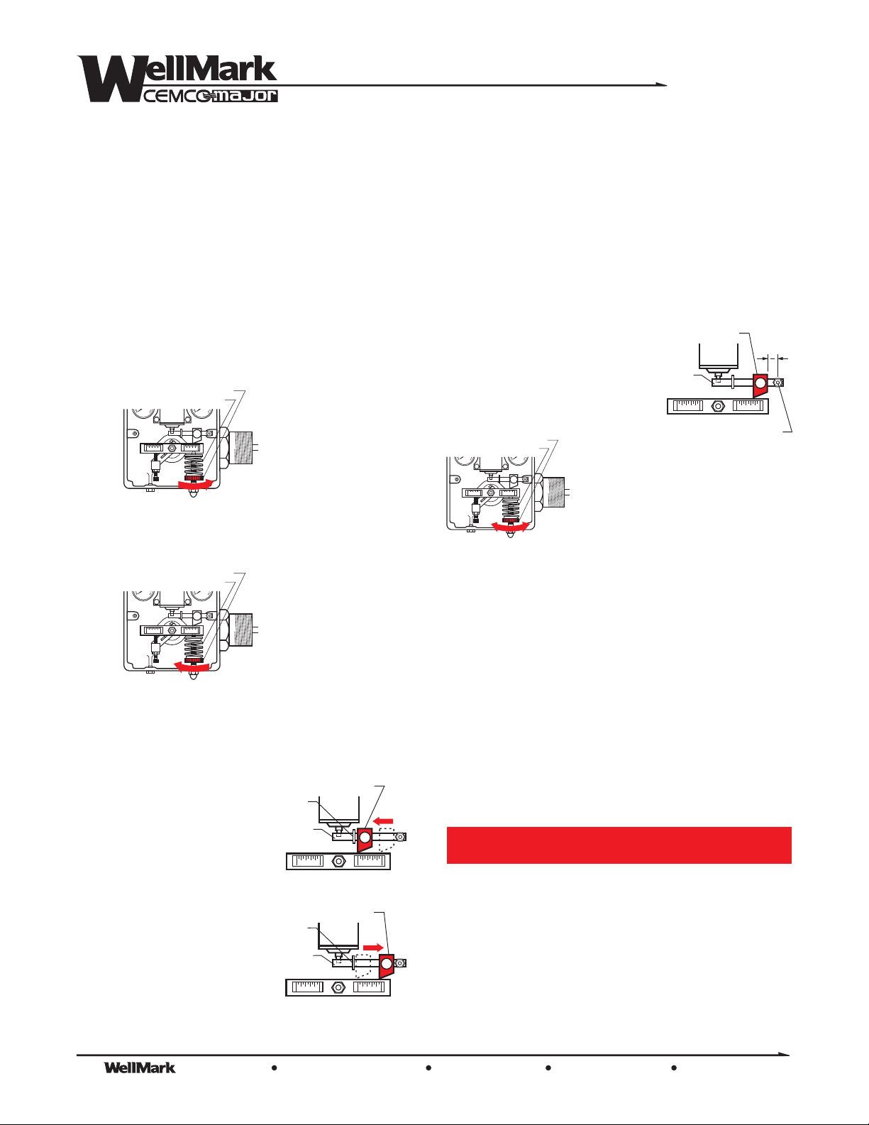
LEVELADJUSTMENT
The controller is factory-set for average level and sensitivity.
To DECREASE LEVEL
turning theAdjustment Wheel to the
ADJUSTMENT WHEEL
To INCREASE LEVEL -
theAdjusting Wheel to the
ADJUSTMENT WHEEL
- Increase the compression of the Spring by
RIGHT.
SPRING
psipsi
DECREASE LEVEL
by increasing Spring compression
RIGHT
Decrease Spring compression by turning
LEFT.
SPRING
psipsi
INCREASE LEVEL
by decreasing Spring compression
SETTING INTERFACE LEVEL
The controller is factory-set for average level and sensitivity.
Generally speaking, interface operation is most successful when
there is a substantial differential in specific gravity between the two
liquids. Interface cannot be reliably achieved with a displacer-type
control with specific gravity differentials less than 0.1. Also, the
sensitivity of the interface control is increased by the size of the
displacer. Therefore, it is usually advantageous to use the largest
displacer available, which will fit into the vessel.
NOTE: The
presence of foam in the interface zone may affect the accuracy
of the control.
FULCRUM
PIVOT
1”
2
1. Set Fulcrum approx. 1/2” from
pivot pin.
ADJUSTMENT WHEEL
SPRING
psipsi
Reduce Spring tension slowly by
FLAPPER
BAR
PILOT
turning the Adjusting Wheel to the
Allow the upperfluid to rise until
LEFT.
it completely submerges the Displacer.
Next, fine-tune the adjustment by turning the Adjusting Wheel to
RIGHT
the until an output signal is attained.
Finally,turn theAdjusting Wheel back to the until the output
signal returns to
ZERO.
LEFT
2. Allow the lower liquid to rise until the desired interface level is
LEFT
ADJUSTING PROPORTIONAL BAND (SPAN)
Loosen Thumbscrew on Fulcrum and position the Fulcrum along the
Flapper Bar.
ToDECREASE BAND
(Increase Sensitivity)
Slide Fulcrum along
Flapper Bar toward
SNAP
RING
FLAPPER
FULCRUM
PILOT
BAR
Snap Ring.
attained. Fine tune by slowly turning theAdjusting Wheel to the
RIGHT
until an output signal is obtained. Finally, slowly turn the
Adjusting Wheel to the until the output signal returns to
LEFT
ZERO.
3. To obtain a shorter dump span, slide the Fulcrum away from the
pivot and repeat the above procedure.
Maintenance
WARNING!
Prior to maintenance of the 2001NB Level Control
system must be isolated from pressure. Failure to
do so may result in personal injury, environmental
spill concerns and/or damageto equipment.
The 2001NB Level Control is designed to provide years of reliable
service. However, build up of debris, paraffin, etc inside the
ToINCREASE BAND
(decrease Sensitivity)
Slide Fulcrum along
Flapper Bar away from
Snap Ring.
SNAP
RING
FLAPPER
BAR
FULCRUM
PILOT
controller Body can interfere with proper functioning. A regular
Once desired band/span is achieved re-tighten Thumbscrew.
maintenance program should include checking for this condition.
The Company, L.L.C. Oklahoma City, Oklahoma Tel: (405) 672-6660 Fax: (405) 672-6661
4
© The WellMark Company • Litho USA • All registered trademarks are the property of their respective owners. • IOM-2001NB 091007
wellmarkco.com
Page 5
Series
2001NB
Maintenance- continued
General Disassembly
Note: This procedure does not include removal or servicing of the
Pilot. Refer to section elsewhere on this page for information
specific to removal of Pilot. Also, for reference see Sectional
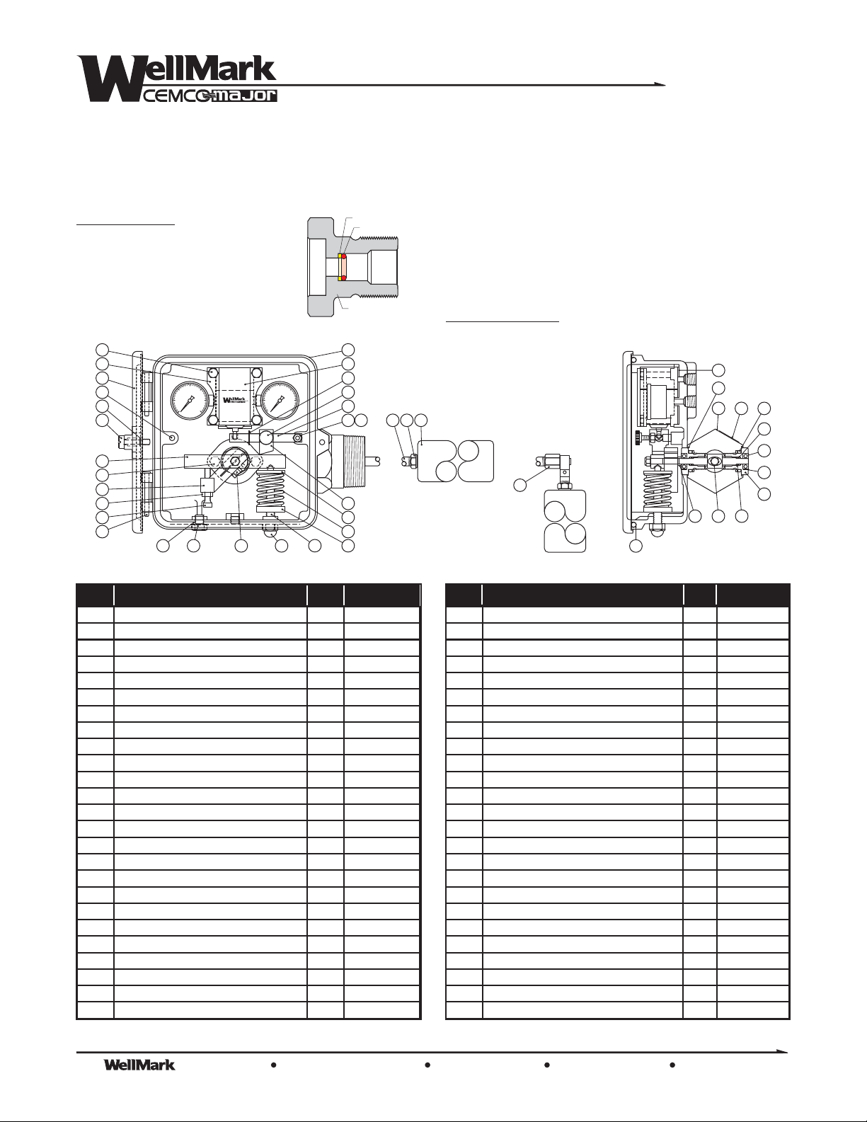
Diagram and Parts List on Page 6.
Relax compression on Spring (21) and remove along with the Upper
Guide (22). Remove the Stud (19) andAdjustment Wheel(20).
Remove NylocNut (28) from Stud (23) and slide the Flapper Bar (24)
off Stud. DO NOT REMOVE THE STUD, as it is press-fit into the
Control Box. Fulcrum (26) and Thumbscrew (27) should remain in
place on the Flapper Bar.
Remove a second Nyloc Nut (28) from the Pivot Shaft (6) and slide
Torque Bar off the PivotShaft (6).
Hold the Adjusting Bar (14) while loosening two Capscrews (15).
Once Adjusting Bar is loose, remove it along with the Adjusting
Screw (17) from the Pivot Shaft. The Adjusting Screw need not be
removed from theAdjusting Bar.
Shaft.
Remove two Capscrews (12) holding the Control Box (1) to theBody
(5) and disassemble Control Box from Body.
Slide the Spacer(11) from the Pivot
Temporarily install the Torque Bar onto the Pivot Shaft. Position the
Level Adjusting Bar andAdjusting Screw such that the Torque Bar is
parallel with the Displacer Arm (30) when the tip of the Adjusting
Screw is touching the bottom of the TorqueBar.
Remove the Torque Bar, being careful not to disturb the position of
the Adjusting Bar, and fully tighten the two Capscrews securing the
Adjusting Bar to the Pivot Shaft. DO NOT OVERTIGHTEN.
Slide the Torque Bar back in place with the hole for the Upper Guide
oriented on bottom and in proper position to accept the Upper Guide
once the Spring is re-installed. Secure the Torque Bar with the Nyloc
Nut, leaving approx. 1/16” clearance between the bottom of the nut
and the Torque Bar.
to move freely on the Pivot Arm. Tightening the Nyloc Nut too
much will inhibit this free travel.
Slide the Flapper Bar back onto the Stud and secure with the other
Nyloc Nut. IMPORTANT! Do not over-tighten this nut, as the
Flapper Bar must be able to move freely on the Stud.
Re-install the Stud and Adjusting Wheel. Install the Spring and
Upper Guide, engaging the extrusion on the Upper Guide into its
mating hole on the bottom of the TorqueBar.
Pilot Removal/Replacement
IMPORTANT! The Torque Bar must be able
General Reassembly
Mount the Control Box to the Bodyusing the two Capscrews. Screws
should be tightened to 6 ft-lbs.
Install the Spacer on the Pivot Shaft.
If the Adjusting Screw was removed from the Adjusting Bar during
disassembly it should be refitted, threading it into the Adjusting Bar
until an equal amount of threads is showing above and below the
Adjusting Bar.
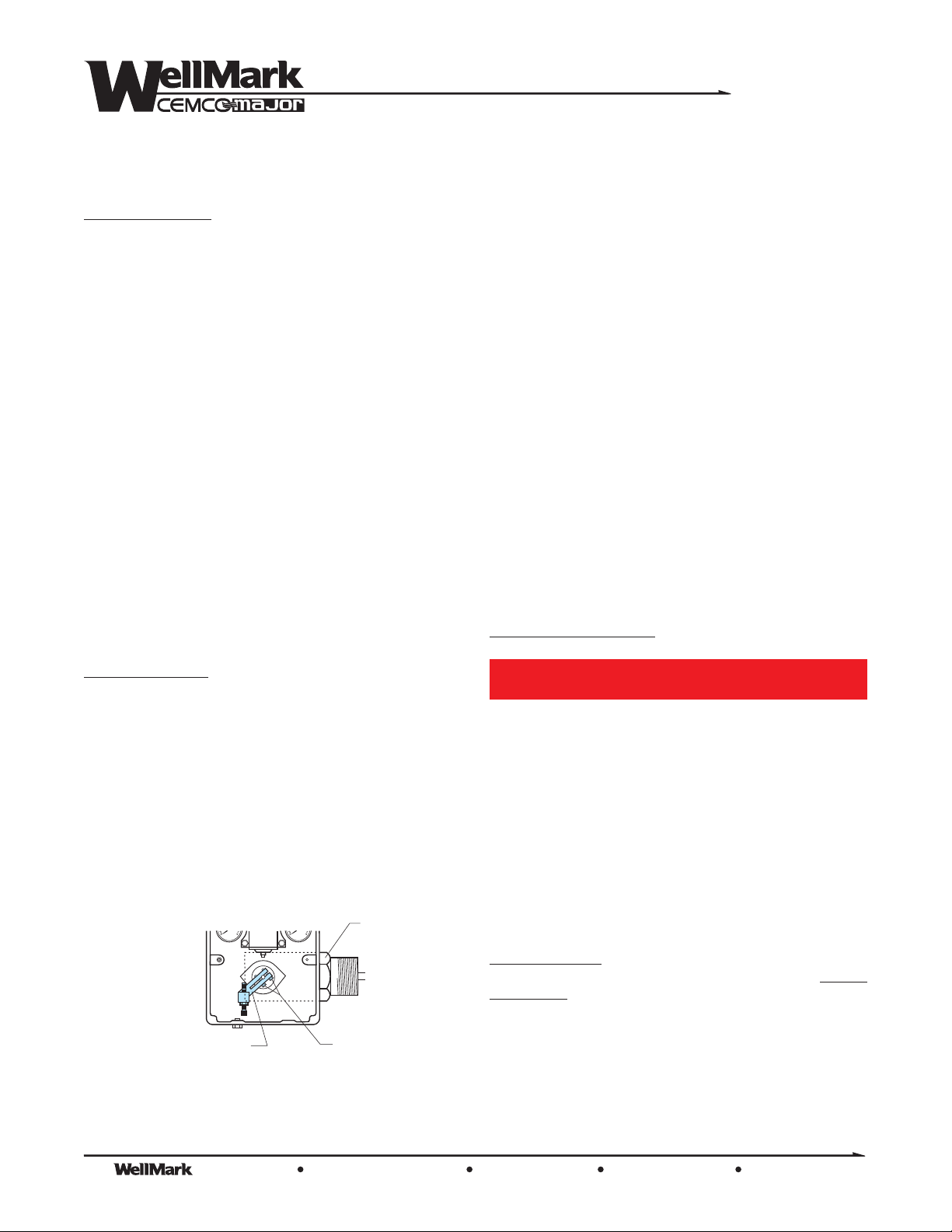
Slide the Adjusting Bar onto thePivot Shaft, against the Spacer, such
that theportion through which theAdjustment Screw isinstalled is on
the opposite side from the Body (see below).
psipsi
ADJUSTMENT
on opposite side from BODY
Snug, but the two Capscrews that hold the Adjusting
Bar to the Pivot Shaft.
do not tighten
BAR
BODY
CAPSCREWS
WARNING!
Prior to removing Pilot system mustbe isolatedfrom
pressure. Failure to do so may result in personal
injury, environmental spill concerns and/or damage
to equipment.
The Pilot (4) is held in place by the Pilot Clamp (36) and four
Capscrews (35). Remove theCapscrews, PilotClamp and Pilot from
the Control Box. Inspect condition of Gasket (34) and replace if
necessry.
Re-install the Pilot, assuring that the Gasket is seated properly with
port holes aligned with ports in Pilot and Control Box.
Body Disassembly
Remove the Body from the Control Box as described in the
Disassembly
CAUTION! If the Shaft Retainers (9) are removed, O-Rings (7
and 10) and Back-up Rings (8) MUST BE REPLACED.
Remove the two Shaft Retainers (9) utilizing a 1-1/8” wrench.
Remove the Pivot Shaft (6). Remove the Pivot Shaft O-Rings (7),
Back-up Rings (8) and Shaft Retainer O-Rings (10) and discard.
section.
General
The Company, L.L.C. Oklahoma City, Oklahoma Tel: (405) 672-6660 Fax: (405) 672-6661
© The WellMark Company • Litho USA • All registered trademarks are the property of their respective owners. • IOM-2001NB 091007
wellmarkco.com
5
Page 6
Series
Item Description Qty. Part Number
25 TRU-ARC RING 1 06000-1385
26 FULCRUM, Aluminum 1 05011-4412
27 THUMBSCREW, SS/Plastic 1 06500-5429
28 NYLOC NUT, SS 2 05000-2567
29 ACORN NUT, SS 1 05000-2575
30 DISPLACER ARM - STD., SS 1 06000-1534
30 DISPLACER ARM - VF, SS 1 05011-9296
31 DISPLACER BUSHING, SS 1 06000-5105
32 DISPLACER - STD., PVC 1 05012-3561
33 HINGE PIN, Plated CS 2 06000-7537
34 GASKET, Neoprene 1 06000-4819
35 CAPSCREW, SS 4 05000-5313
36 PILOT CLAMP, SS 1 05012-6325
37 PANEL SCREW, SS 1 06000-1153
38 RETAINER, SS 1 06000-2672
39 SERIAL TAG, Aluminum (not shown) 1 06000-1922
40 THREAD SEAL, Steel/Buna N 1 06000-0395
41 O-RING, Viton® 1 05000-5586
42 BEARING, SS 2 06000-7552
43 TOLERANCE RING, SS 2 06000-7560
44 ADAPTER, VERT. DWN ASSY., SS 1 06500-4350
45 COVER GLASS, Lexan® (not shown) 2 10916
46 COVER GLASS PLATE, SS (not shown) 2 10915
47 COVER GLASS GSKT, Neoprene (not shown) 2 10917
48 SCREW, Plated Steel (not shown) 8 001501P
Item Description Qty. Part Number
1 CONTROL BOX, Die Cast Aluminum 1 05012-4841
2 COVER, Die Cast Aluminum 1 05012-4834
3 BOX SEAL, Neoprene 1 06000-5097
4 SNAP PILOT ASSY., Aluminum & SS 1 06500-5304
4 THROTTLE PILOT ASSY., Aluminum & SS 1 06500-5387
5 BODY, CS 1 05011-4560
6 PIVOT SHAFT, SS 1 05011-4511
7 O-RING, Viton® 2 05000-0769
8 BACK-UP RING, Teflon® 2 06000-1179
9 SHAFT RETAINER, SS 2 05012-9389
10 O-RING, Viton® 2 05000-1155
11 SPACER, SS 1 05011-4495
12 CAPSCREW, SS 2 05000-5578
13 CAPSCREW, SS 1 05000-5453
14 ADJUSTING BAR, Aluminum 1 05011-4438
15 CAPSCREW, SS 2 05000-2526
16 TORQUE BAR, Aluminum 1 05011-4545
17 ADJUSTING SCREW, SS 1 05011-4537
18 JAM NUT, SS 1 05000-2559
19 STUD, SS 1 05011-4552
20 ADJUSTMENT WHEEL, Aluminum 1 05011-4529
21 SPRING, SS 1 06000-4157
22 UPPER GUIDE, Aluminum 1 05011-4479
23 STUD, FLAPPER BAR, SS 2 05012-9371
24 FLAPPER BAR, SS 1 05011-4404
2001NB
The Bearings (42) and Tolerance Rings (43) need not be removed
from the Shaft Retainers unless they are damaged and must be
replaced.
Body Reassembly
Lightly lubricate new O-Rings and Back-
BACK-UP RING (8)
O-RING (7)
Up Rings with oil. Install Pivot Shaft
Back-Up Ring into Shaft Retainers first,
with O-Ring next. IMPORTANT! The
Back-Up Ring MUST be outboard of
the O-Ring,as illustrated.
35
36
2
23
38
37
16
12
14
18
17
33
15
10
20
255
030
SUPPLY
40
13 15 29 19
10
030
OUTPUT
15
20
255
SHAFT RETAINER (9)
1
4
25
27
24
23 30 31 32
28
26
22
21
20
Horizontal Displacer
Thread the Shaft Retainer into theBody.
outboard
Insert the Pivot Shaft into the Body from the inboard side, seating it
firmly into the Bearing in the Shaft Retainer on the side
outboard
Re-install the remaining Shaft Retainer over the Pivot Shaft and
threaded into the side of the Body. Tighten both Shaft
inboard
Retainers firmly.
Re-attach the assembledBody tothe ControlBox as described in the
General Reassembly
44
Assembly
section.
Vertical Displacer
Assembly
34
41
5
6
11
3
10
39
8
42
43
9
7
Parts List
The Company, L.L.C. Oklahoma City, Oklahoma Tel: (405) 672-6660 Fax: (405) 672-6661
6
© The WellMark Company • Litho USA • All registered trademarks are the property of their respective owners. • IOM-2001NB 091007
wellmarkco.com
 Loading...